Abstract
A new idea for a contra-rotary ramjet engine is presented. To define the theoretical limits of the non-typical, contra-rotary ramjet engine configuration, its analytical model was developed. The results obtained from that model and the analytical results were compared with those received from numerical simulations. The main weakness of existing rotary ramjet engine projects is the very high rotational speed of the rotor required for achieving supersonic inlet flow. In this paper, a new idea for a contra-rotary ramjet engine (CORRE) is presented and analyzed. This paper presents the results of analytical analysis and numerical simulations of a jet engine system with two rotors rotating in opposite directions. Contra-rotating rotors generate a supersonic air velocity at the inlet to the compressor at two times slower rotor’s speed. To determine the flow characteristics, combustion process, and engine efficiency of the double-rotor engine, a numerical solution of the average Navier-Stokes equations was used with the k-eps turbulence model and the non-premixed combustion model. The results of numerical simulations of flow and the combustion process inside the contra-rotary jet engine achieving a shockwave compression are shown and compared with similar data for a single-rotor engine design and analytical data. This paper presents only the calculation results of the flow processes and the combustion process, indicating the advantages of the proposed double-rotor design. The results of the numerical analysis were presented on the contours and diagrams of the pressure and flow velocity, temperature distribution, and mass fraction of the fuel.
1. Introduction
The concept of a rotating jet engine is an old idea. The first helicopter designs equipped with ramjet engines, placed at the main rotor’s blade tips and transferring the generated torque directly to the rotor itself, were created in the 1950s [1]. Based on the concept of a jet engine with shockwave compression [2], the idea of a rotational supersonic engine generating torque [3] was created. Due to the benefits that are possible with jet engines using shockwave compression and torque generation, many proposals for such designs have been made around the world. A very high rotational speed is necessary to obtain the supersonic flow of the working medium at the inlet to these devices, which is their characteristic feature. These speed levels result in high centrifugal forces acting on the rotor, thus creating a great challenge from the point of view of the structure’s strength [4]. Despite these complications, many concepts of rotational supersonic engines have been created. Some of them are merely theoretical considerations [4], while there are also cases of technical designs [5,6,7,8,9,10]. A comprehensive description of a rotary ramjet design is presented in Picard et al. [11]. A very general description without details can be found in Madasamy et al. [12]. New ideas for combustion in rotary ramjet engines are considered in Brouillette et al. [13].
In 1998, Ramgen Power Systems proposed the first rotary ramjet for on-ground power generation [2]. The pre-prototype engine was fully assembled in July 1998. In 1999, tests validated the ignition phase, flame holding at idle rotor speeds, mechanical integrity of the rotor at supersonic tip speeds, and overall system integrity. The engine was designed to operate at 500 m/s (Mach number 1.5), with thermal (cycle) efficiencies comparable to gas turbines. The Ramgen company continued development of the shockwave compression idea with the technical realization of the CO2 compressor based on this principle [5] and considered building a flow engine. In 2004, Ramgen developed a rotary engine design that utilizes the compression generated by the supersonic engine air inflow. Development continues and in considered solutions compression ratios reach values of 30 [6].
The structural design and experimental validation of a proof-of-concept prototype of a rotary ramjet engine is presented in Rancourt et al. [14]. The engine can sustain a 500 m/s tip speed at 200 krpm and transient combustion, which is initiated by an integrated ignition system. Part II [14] presents a discretized, one-dimensional (1-D) aerothermodynamic model that estimates the engine performance. A simple buoyancy-driven combustion model makes it possible to estimate the combustor length and shows good agreement with numerical simulations, which demonstrates that the combustion efficiency is higher than 85%, which includes some reactants bypassing the flame holder [15]. A thermodynamic analysis of a rotary ramjet engine with internally open ram channels has also been considered in Dahm et al. [16]. The theory of a moving shockwave compression and non-heated flow field in the ram-compressor rotor disk cavity was analyzed in Wang et al. [17]. There are also results of numerically solved steady 3-D Reynolds Average Navier-Stokes (RANS) equations. In conventional, high rotational speed designs, the rotor requires a special type of bearing [18].
The authors analyzed one of the possible solutions of such an engine in a previous study [19]. Starting from the classic design of a jet engine used in aviation [2], a geometric model of a rotational jet engine was prepared and subjected to an optimization process. Analyzing the results of subsequent calculations, the shape of all channels was modified to obtain the best possible performance of such a construction.
In addition, a relatively wide range of typical engine operating parameters was considered, which in this case involved different rotational speeds and the consumption of fuel injected into the combustion chamber [19].
An analysis of the numerical calculation results made it possible to consider other construction solutions for the engine in the form of a rotary ram jet engine. Despite satisfactory performance (efficiency at 20%), the engine has been subjected to further modifications. The main purpose of these activities was to further increase the efficiency and to reduce the relatively high speed at which the motor shaft should rotate (speeds up to 30,000 revolutions per minute). A presentation of these modifications, as well as an analysis of their impact on engine operation, is the subject of this paper.
One of the main challenges associated with the design of such engines are flow calculations. This study used the current possibilities of numerical analysis for 2-D flow calculations with combustion.
The presented contra-rotary ramjet engine (CORRE) idea is based on the results of an analysis of the features of an earlier investigation of a single-rotor rotary ramjet engine [19]. Therefore, some basic information about this solution is presented. Laube et al. [19] presents an extensive description of the process of searching for the correct shape of the single-rotor rotary shockwave compression engine channels. Various shapes of the engine flow channels were considered and their impact on the compression processes, as well as the combustion process, were analyzed. As a result, the geometry of the engine channels was optimized, ensuring that the operating parameters of the entire engine were at a level close to simple turbine engines.
In contrast to existing publications, which concentrate on some specific aspects of rotary ramjet engine construction, the presented study not only presents the novelty of the idea, but also presents a complex model containing the details of the compressible flow, accompanied by the combustion model, which were both solved by the CFD technique and compared with the analytical model.
2. Analytical Analysis of a Contra-Rotary Ramjet Engine
Because a contra-rotary ramjet engine does not exist physically, it was necessary to find a reference example.
Therefore, a simplified analytical model of the physical processes existing in the considered engine construction was built and used for the prediction of the basic engine operational parameters.
2.1. Ramjet Idea
The ramjet is a simple engine concept that is a combination of a special inlet channel achieving compression in a shockwave system; a diffuser achieving subsonic air compression; a burner (or combustion chamber) achieving heat addition; and a nozzle expanding exhaust gases that generates thrust, and finally, torque. The engine scheme and an example pressure distribution is shown in Figure 1.
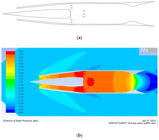
Figure 1.
(a) Scheme of the ramjet engine geometry; and (b) an example pressure distribution with a single normal shockwave structure [19].
The design has no moving parts, compression is realized due to the supersonic motion of the engine in relation to the stationary air.
During this process, the air flow velocity decreases from supersonic to subsonic speeds by means of two typical oblique shockwave systems accompanied by a normal shockwave inside the diffuser, increasing the air pressure in the combustion chamber. In the fixed combustor area (consisting of fuel injectors and flame holders) at high air pressure, mass is added through fuel injection. Then, heat is generated by burning the fuel mixed with the incoming air flow. Finally, the Laval nozzle expands the outgoing combustion flow, converting potential energy to kinetic energy to produce thrust. This solution is known and tested in many supersonic engines.
2.2. Rotary Ramjet Engine
The rotary ramjet engine involves the idea of locating a series of channels of ramjet engines on the tip part of a fast-rotating disk to achieve supersonic air velocity in the vicinity of the engine inlets. The disk drives the engine channels to supersonic speeds before the engine starts, and transmits torque generated during the engine’s operation.
A typical shockwave compression set comprises two oblique shockwaves and a normal shockwave, and depending on the heat release, (at a high release ratio) can be reduced to a single normal shockwave.
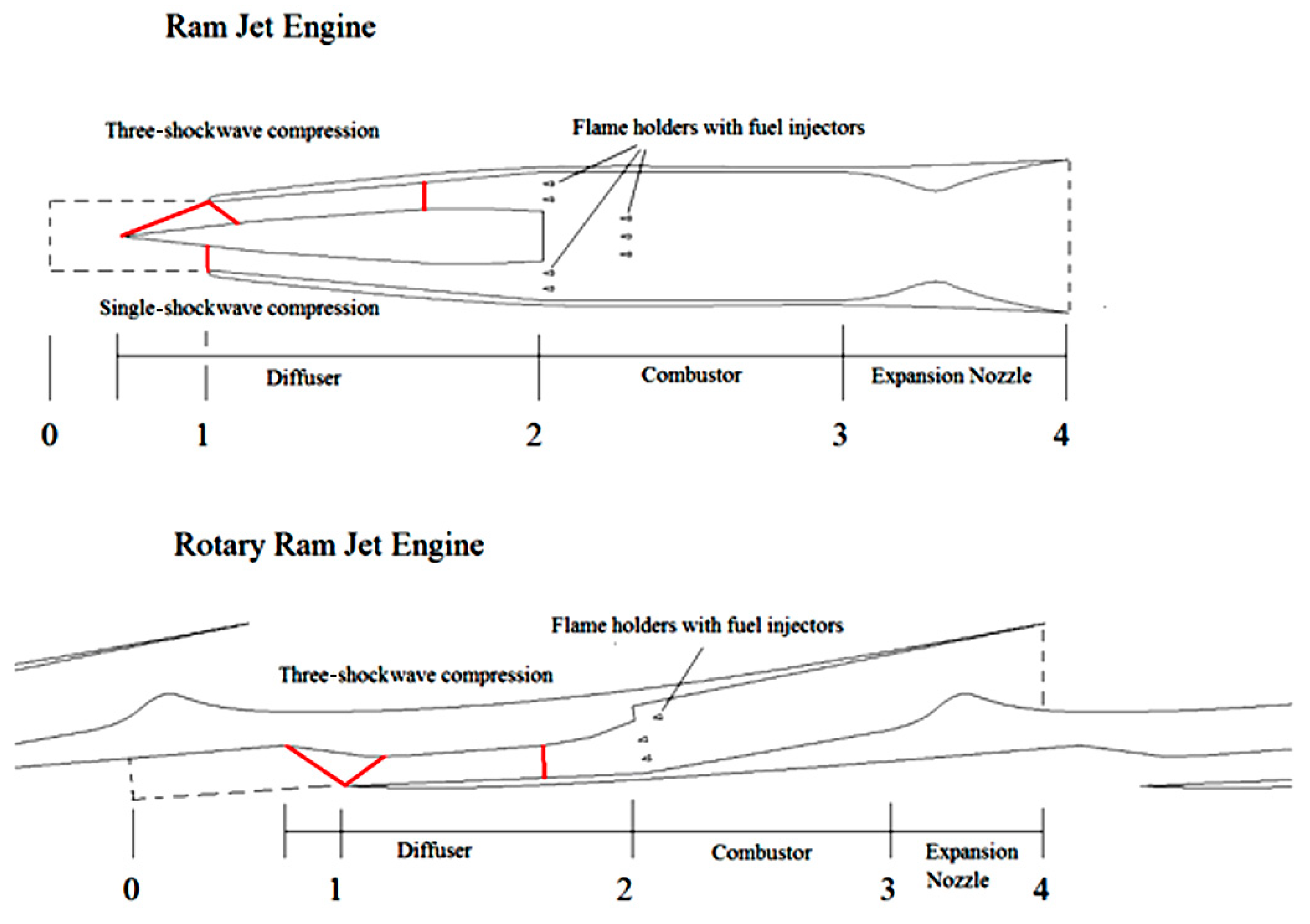
Figure 2 shows a comparison of a typical ramjet engine geometry that is axisymmetric and a rotary ramjet engine geometry that is essentially planar.

Figure 2.
Comparison of axisymmetric geometry of a typical ram jet engine and the planar geometry of the rotary ram jet engine. Markers: 0—define the external conditions, 1—inlet cross-section, 2—combustion chamber inlet, 3—nozzle inlet, 4—nozzle outlet.
2.3. Contra-Rotary Ramjet Engine
A contra-rotary ramjet engine uses an additional axial compressor rotating in the opposite direction to the rotation of the main rotor to increase the air velocity in front of the main rotor ramjet engine inlets. It is driven by the additional axial turbine located outside the main rotor exhaust gas outlets. An additional compressor and additional turbine are located on the auxiliary rotor and rotate with the same rotational speed.
In front of the main rotor inlets, the tip velocities of the compressor rotor and the main rotor are summed, and behind the main rotor, the inlet velocity on the turbine blades is equal to the difference between the main rotor tip speed and turbine tip speed, as shown in Figure 3.
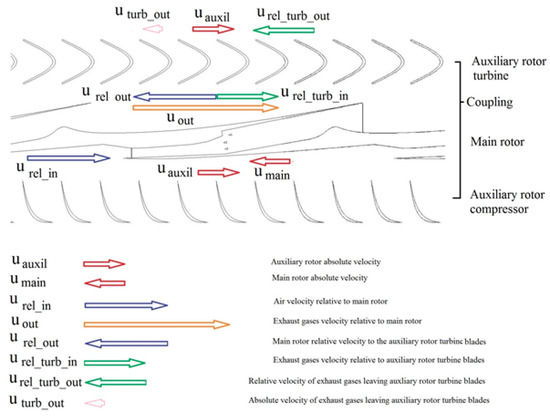
Figure 3.
Contra-rotary ramjet engine idea and features.
The flow structure is different on the turbine side because the relative velocity of the exhaust gases reaching the turbine blades is reduced by the sum of the absolute values of the main rotor and the auxiliary rotor speeds. Therefore, the device is operational if the speed of the exhaust gases leaving the main rotor is significantly larger than the sum of the absolute values of the main rotor and the auxiliary rotor speeds.
The main advantage of the contra-rotary ramjet engine is that the main rotor and the combined additional compressor and turbine driving it can rotate with speeds that are half that required for a single main rotor to obtain the expected inlet Mach number. This feature dramatically reduces the technical problems of engine design.
The analyzed engine contains two rotors rotating in opposite directions. The main rotor contains classic rotary ramjet engine components. These are the inlet compression system in the shockwave system, the diffuser, the combustion chamber, and the supersonic outlet nozzle. The secondary (auxiliary) rotor includes subsonic compressor blades and action turbine blades located in front of and behind the main rotor, respectively. The subsonic compressor is designed to increase the peripheral speed of the air entering it to a speed close to the speed of sound at its outlet.
The action-type turbine that drives the subsonic compressor spins at the same speed as the compressor.
The main rotor compression system is shaped like a side surface and the inlet channel is shaped such that it generates two oblique waves. The first is the shockwave arising on the ramp of the side surface of the main rotor with an angle of 12° relative to the direction of the air inflow. The second wave is formed in the area behind the first shockwave, at the inlet blade to the engine channel, at an angle of 10° to the direction of air flow behind the first shockwave. The second shockwave changes the direction of air flow parallel to the inlet channel walls and does not create a reflected wave.
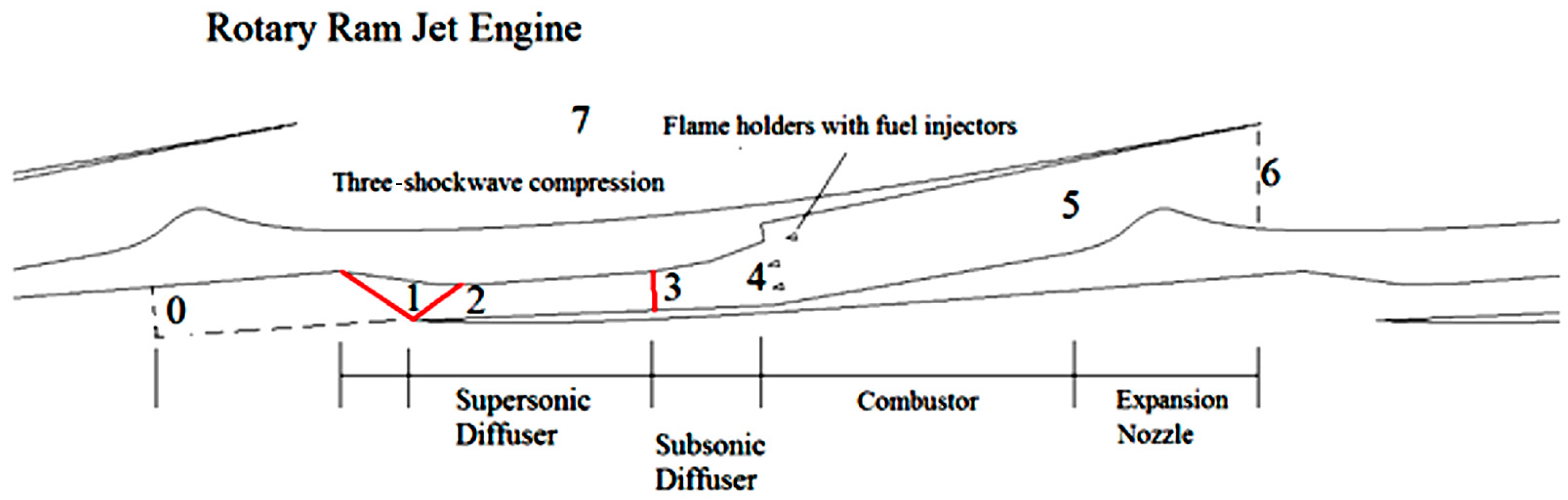
The arrangement of these oblique waves is terminated by a normal shockwave located in the engine diffuser in front of the combustion chamber (see Figure 4).
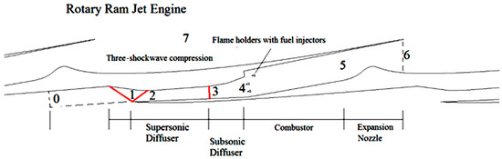
Figure 4.
Characteristic areas and cross-sections of the main rotor of a rotary ram jet engine. Markers: 0—define the external conditions, 1—area behind primary oblique wave, 2—area behind secondary oblique wave, 3—area behind the normal shock wave, 4—combustion chamber inlet, 5—nozzle inlet, 6—nozzle outlet.
Figure 3 explains the basic relationship between the velocities existing inside and between different moving elements of the engine.
2.4. Analytical Contra-Rotary Ramjet Engine Model
The proposed model can be divided into two parts. The first part covers the flows inside the main rotor and the second part concentrates on the flows inside the auxiliary rotor.
2.4.1. Compression
Given the inlet geometry shown in Figure 4 and the Mach number in front of the inlet makes a shockwave configuration possible with two oblique shockwaves and a single normal shockwave, it is possible to analytically calculate the compression ratio and static temperature increase of air reaching the combustion chamber. Figure 4 presents numbered areas separated by the shockwaves in the initial supersonic part of the flow and numbered characteristic flow cross-sections in the subsonic and outlet supersonic areas.
The area represented by the number 0 is an inlet supersonic area. Area number 1 represents the supersonic flow downstream of the first oblique shock with a changed flow direction. Area number 2 represents the supersonic flow in the supersonic diffuser downstream of the second oblique shockwave, which achieves a flow direction parallel to the diffuser walls and does not generate a reflection of the oblique shockwave. Area number 2 is separated by the normal shockwave from the subsonic area downstream. Cross-section number 3 represents the air parameters after the normal shockwave. Between cross-sections 3 and 4, there exists a subsonic diffuser that produces an increase of the channel cross-section. The combustion chamber starts at cross-section 4. Cross-section number 5 represents the inlet to the supersonic expansion nozzle, while number 6 indicates the outlet of the expansion nozzle.
Between cross-sections 4 and 5, a combustion process with constant pressure is produced according to the ideal Brayton cycle. Furthermore, between cross-sections 5 and 6, an ideal expansion process through the Laval nozzle (p6 = p0) is assumed. The working fluid inside the engine to the combustion chamber is air, which is assumed to behave as a perfect gas with a constant specific heat. Inside the combustion chamber, air is mixed with the fuel and burned. Exhaust gases leaving the combustion chamber have a different ratio of specific heat at constant pressure and constant volume (ke).
Equations describing the gas dynamics of supersonic and subsonic flows can be found in many elementary books, such as References [20,21,22,23].
The oblique shockwave is generated by the rapid change of the flow direction by a ramp inclined to the flow by angle which causes the oblique shockwave inclination .
Unfortunately, the relation between the upstream Mach number M, ramp inclination angle , and oblique shockwave angle is in an implicit form. For the first oblique shockwave, such a relation is presented by Equation (1):
After finding the numerical solution of Equation (1), the oblique shockwave angle can be found by knowing the Mach number M0 and the ramp angle .
The Mach number downstream of the oblique shockwave M1 is expressed by Equation (2):
The compression ratio is described by Equation (3):
The loss of mechanical energy is represented by the stagnation pressure ratio:
The static temperature ratio is described by Equation (5):
Using Equations (1)–(5) and the inlet channel geometry (angles and ), it is possible to define, in a similar way, the flow parameters after two oblique shockwaves.
The supersonic diffuser is designed to transfer these flow parameters to the initial cross-section of the subsonic diffuser where the normal shockwave is located.
The Mach number downstream of the normal shockwave is defined by Equation (6):
The static pressure ratio is given by Equation (7):
The compression efficiency is described by the stagnation pressures ratio:
The temperature rise is described by Equation (9):
The flow in the subsonic diffuser is assumed to be isentropic.
The critical area of cross-section corresponding to the value of the cross-section A3 downstream of the normal shockwave and flow parameters downstream of the shockwave is the same along the subsonic diffuser and can be defined as:
which makes it possible to obtain the Mach number M4 at the end of the subsonic diffuser, just at the inlet to the combustion chamber. Knowing A3 and A4, it is possible to find the Mach number M4 from Equation (11):
The subsonic combustion ramjet combustor flow velocities correspond to an M4 that is typically between 0.3 and 0.35.
In a recent paper, the use of a more detailed model of heat addition, as suggested in References [24,25], takes into account the variation of the Mach number in a combustion chamber and the drop of static
and stagnation pressure () caused by the heat delivery, and is based on equations relating the local stagnation temperature to the critical stagnation temperature [23]:
and the relationship between stagnation pressure and the critical stagnation pressure:
The Mach number M5 for the combustion chamber outlet can be found because the inlet and outlet combustion chamber stagnation temperature are known; therefore, the stagnation pressure on the combustion chamber outlet also can be found. Notice the relation
The combustion process can be modeled as an increase of the stagnation temperature from T04 = T00 to T05 due to the heat release during the burning process. Therefore, the stagnation temperature in the inlet T04 = T00 and at outlet from combustion chamber T05 are important.
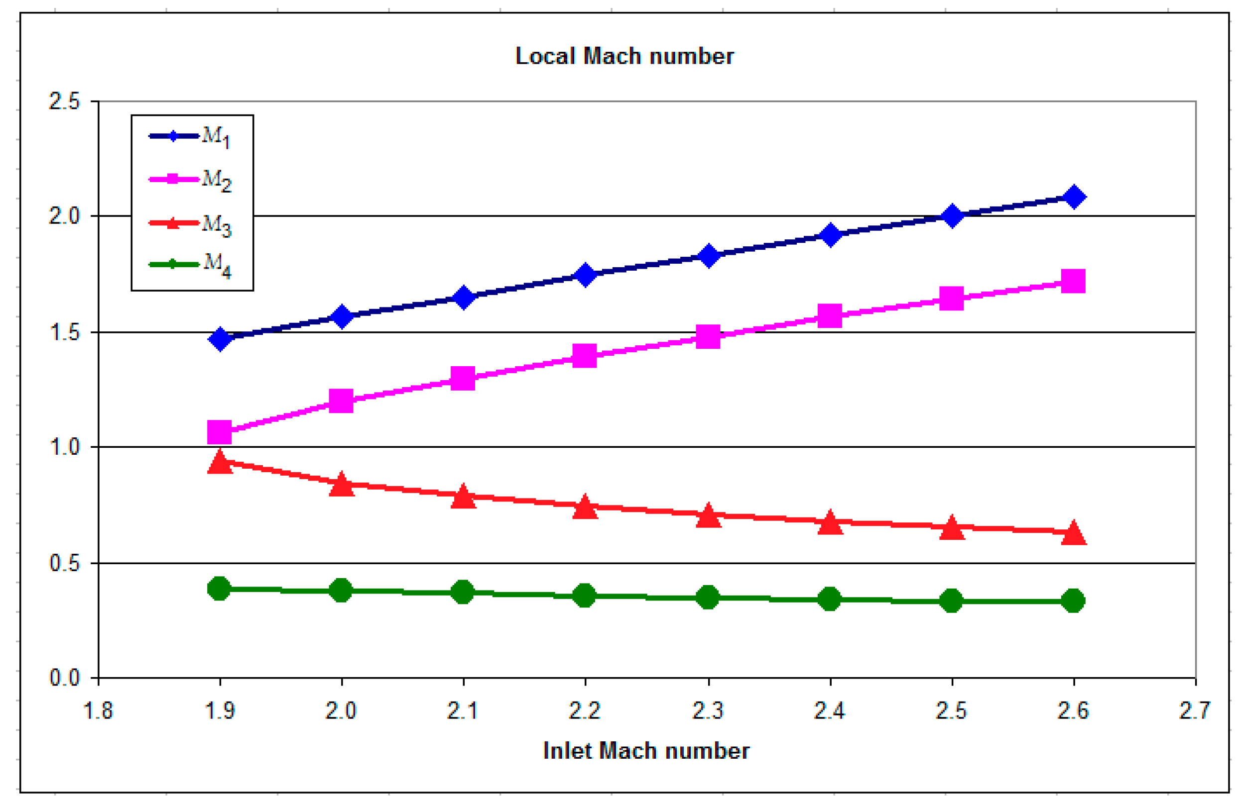
With the assumed geometry of the inlet channel, the described shockwave structure can exist when the initial Mach number is higher than 1.86, such that the calculation starts from a Mach number equal to 1.9 and ends with a Mach number of 2.6 due to high energy losses in the shockwaves.
Figure 5 shows the variation of local values of the Mach number after the primary oblique shockwave (M1), after the secondary oblique shockwave (M2), after the normal shockwave (M3), and on the combustion chamber inlet cross-section (M4).
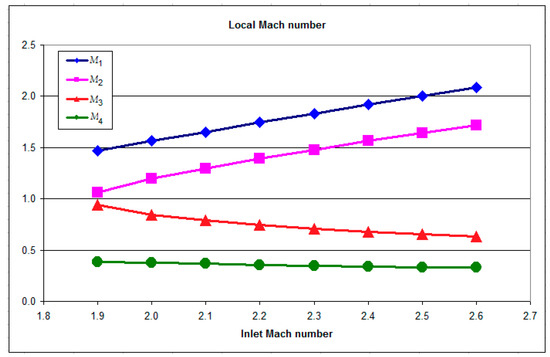
Figure 5.
Local values of the Mach number in the following cross-sections: after the primary oblique shockwave (M1), after the secondary oblique shockwave (M2), after the normal shockwave (M3), and on the combustion chamber inlet cross-section (M4).
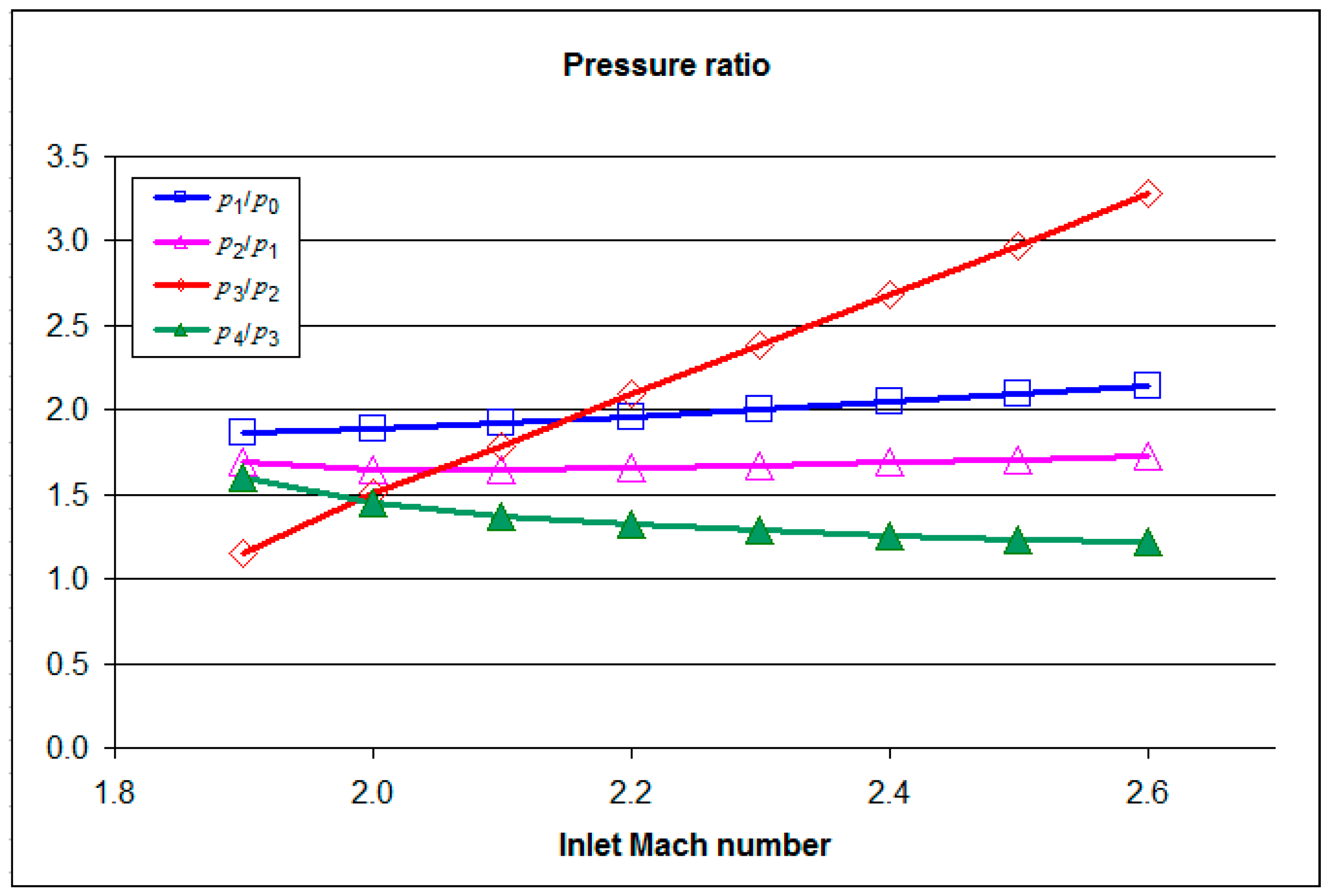
In Figure 6, local values of the static pressure compression ratio after the primary oblique shockwave (p1/p0), after the secondary oblique shockwave (p2/p1), after the normal shockwave (p3/p2), and for the combustion chamber inlet cross-section (p4/p3) are depicted.
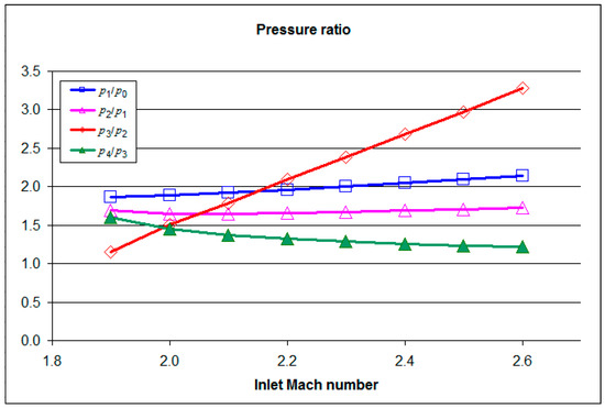
Figure 6.
Local values of compression ratios in the following cross-sections: after the primary oblique shockwave (p1/p0), after the secondary oblique shockwave (p2/p1), after the normal shockwave (p3/p2), and for the combustion chamber inlet cross-section (p4/p3).
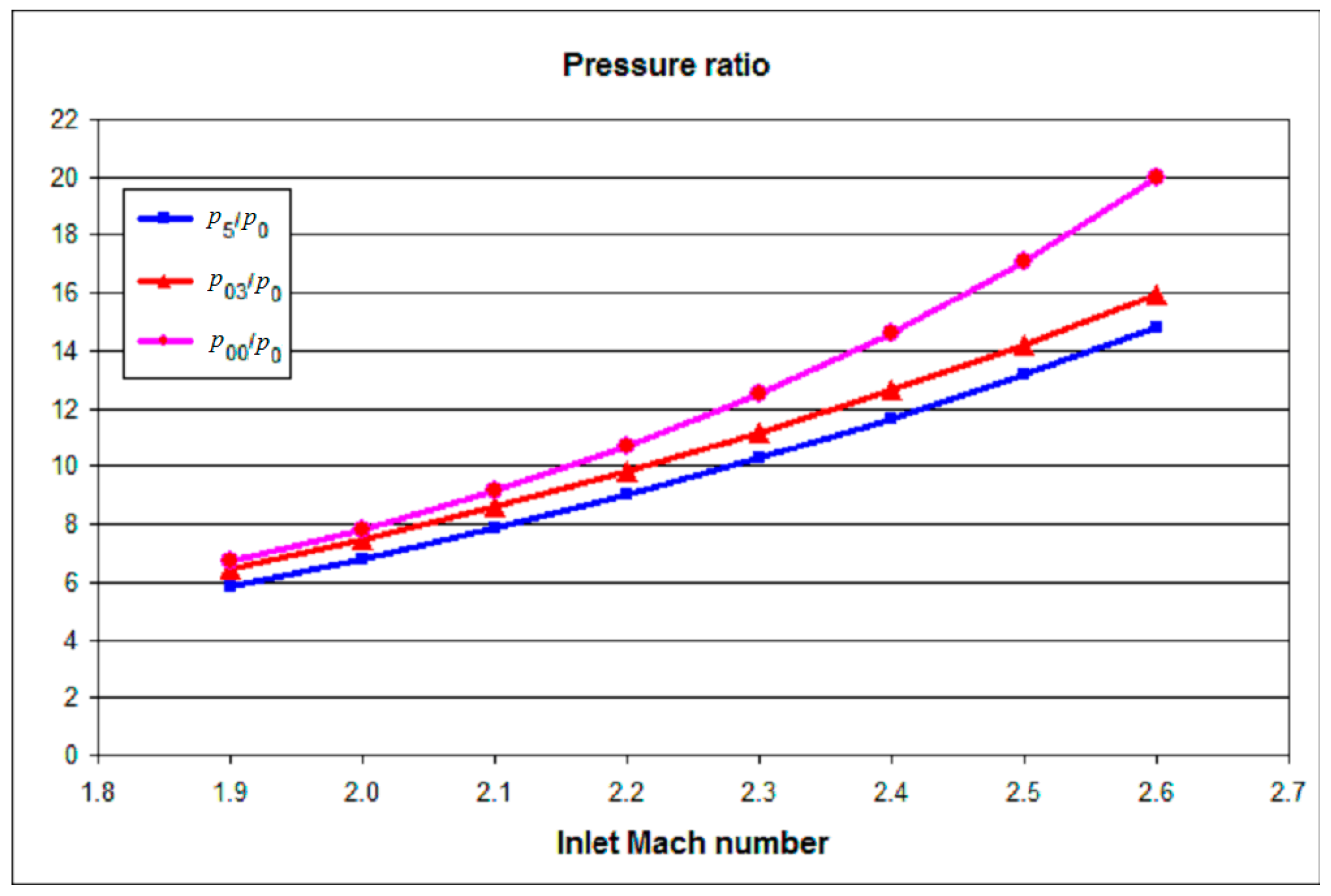
In Figure 7, the compression ratio of the static pressure in the combustion chamber inlet cross-section to the static inlet pressure, ratio of the stagnation pressure after the shockwave system to the inlet static pressure, and the ratio of the stagnation pressure after the ideal isentropic compression to the static inlet pressure versus the inlet Mach is presented.
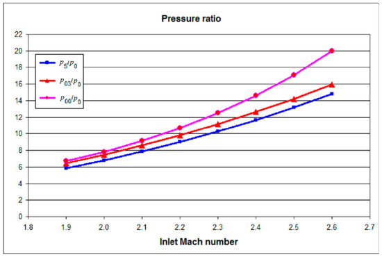
Figure 7.
Local values of stagnation pressure to static inlet pressure after isentropic compression (p00/p0), after the shockwave system (p03/p0), and the ratio of the static pressure at the combustion chamber inlet to inlet pressure (p5/p0).
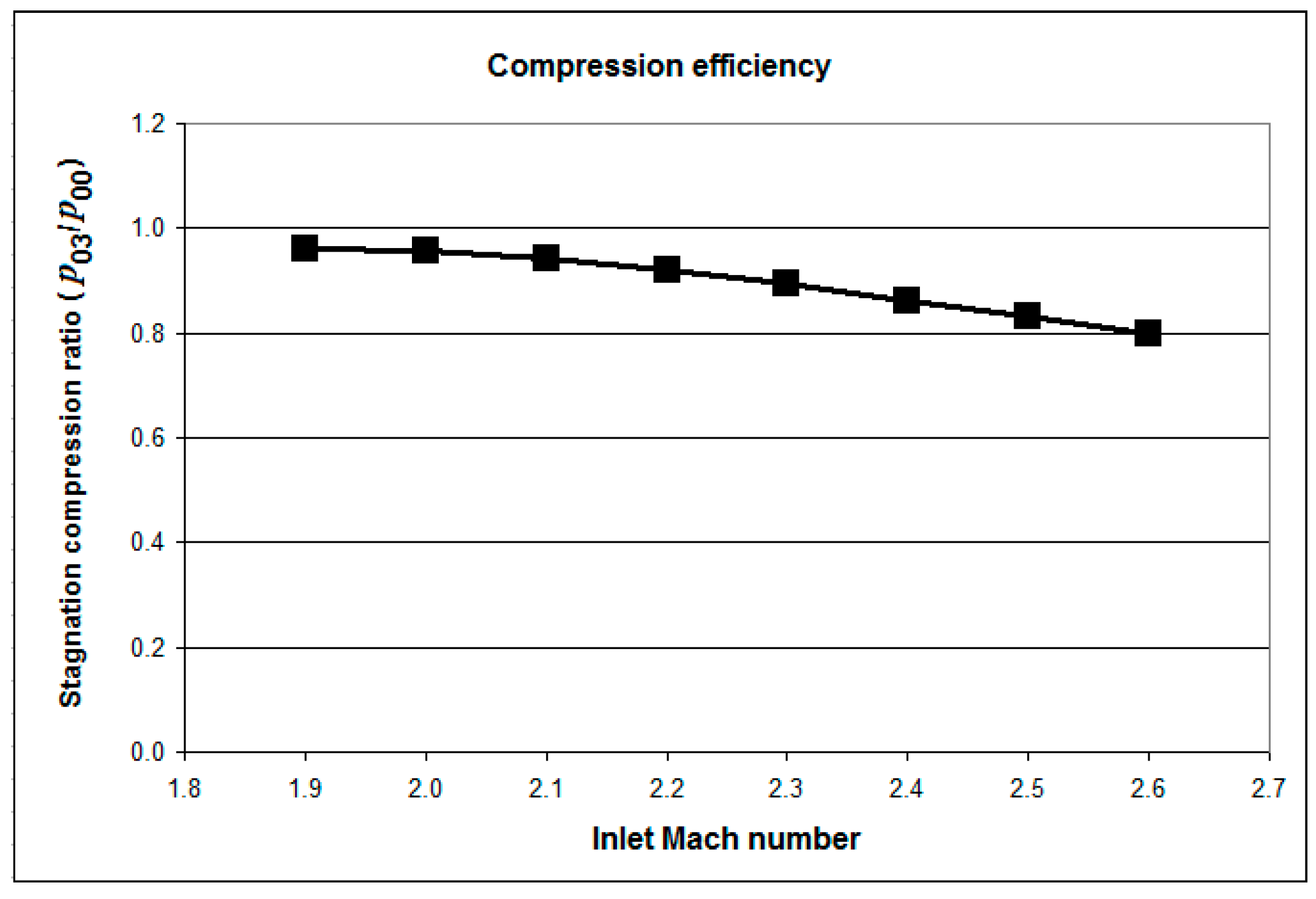
The compression efficiency in the set of two oblique shockwaves and one normal shockwave is given by the ratio of the stagnation pressure on the combustion chamber inlet cross-section to the pressure achieved in an ideal isentropic compression, as presented in Figure 8.
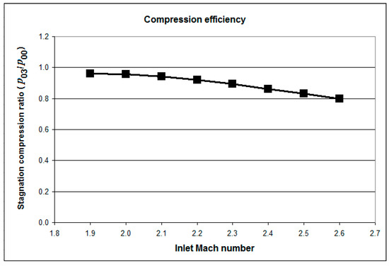
Figure 8.
Compression efficiency in the set of two oblique shockwaves and single normal shockwave represented by the stagnation pressure ratio (p03/p00).
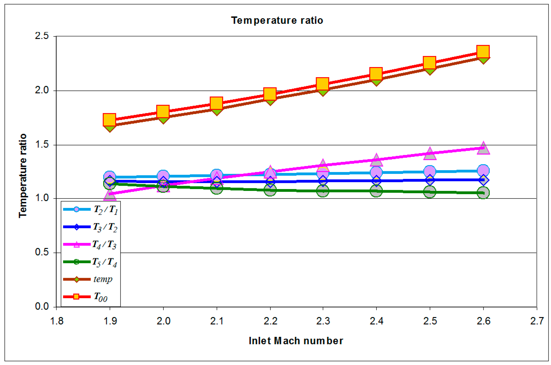
The air compression in a set of oblique and normal shockwaves was accompanied by an increase in static air temperature, as shown in Figure 9. The initial static air temperature rose to more than twice its initial value in the analyzed range of Mach numbers at the inlet to the engine. The air temperature at the inlet to the combustion chamber ranged from 500 K at M = 1.9 to 680 K at M = 2.6. Such a high air temperature at the inlet to the combustion chamber is one of the disadvantages of shockwave compression.

Figure 9.
Local values of the static temperature ratio after isentropic compression (T00), after the shockwave system (T03/T00), and the static temperature at the combustion chamber inlet (T5/T1).
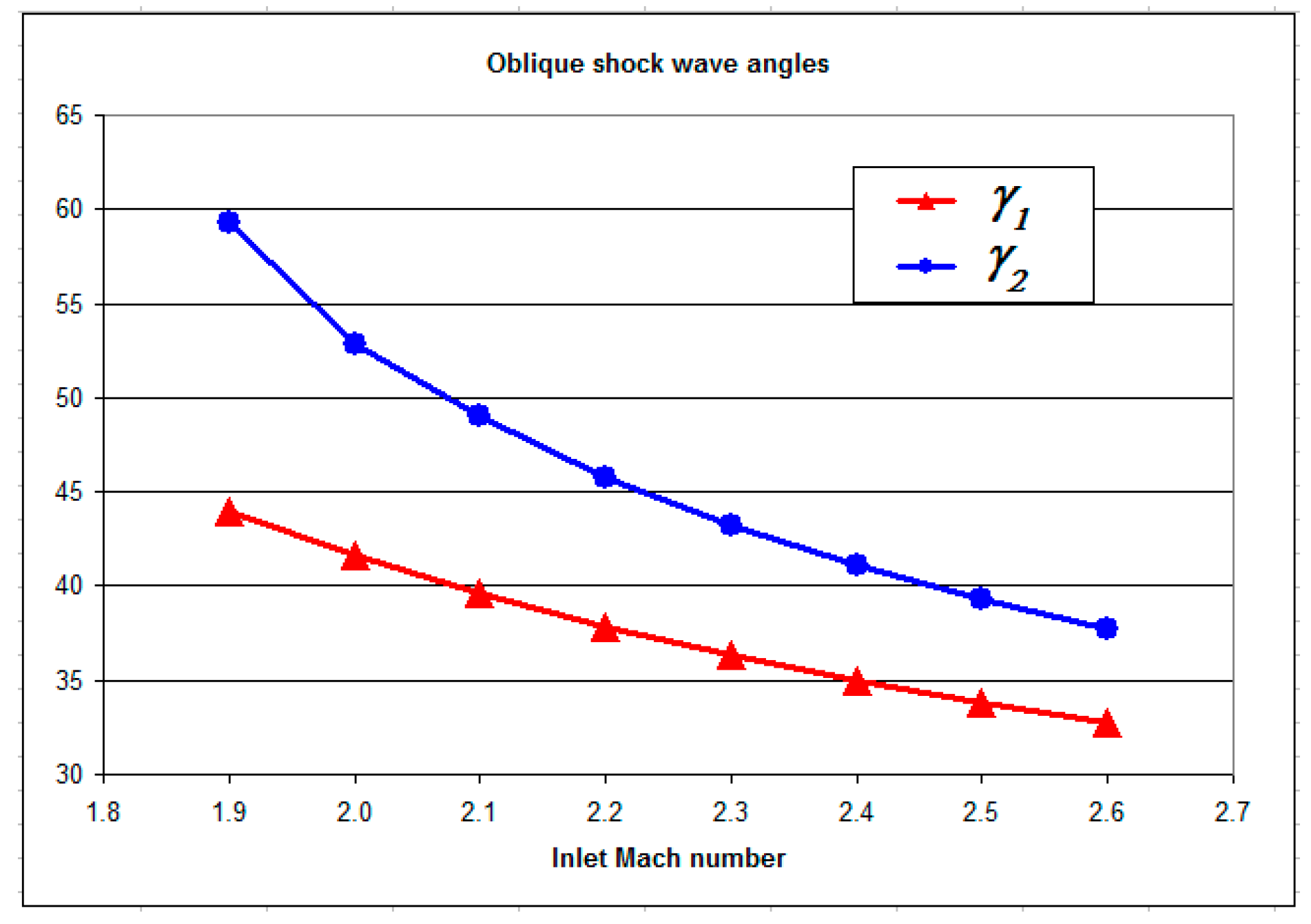
At the same ramp angles in the main rotor inlet channel, for different inlet Mach numbers, the oblique shockwave inclination varied, as shown in Figure 10, which required modification of the engine inlet geometry or operation with a non-optimal configuration with side effects.
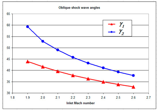
Figure 10.
Angles of primary and secondary oblique shockwaves generated by the inlet flow at different Mach numbers.
2.4.2. Combustion
One of the most important parameters for defining a ramjet engine operation is the temperature of the compressed air at the inlet to the combustion chamber. In Figure 9, the local temperature rise in the shockwave system is shown, giving the variation of the combustion chamber inlet temperature ratio with the engine inlet static temperature.
The combustion process was simulated by introducing fuel in various quantities and assuming set values of the excess air coefficient. By assuming the stoichiometric air-fuel ratio and the excess air ratio nair, the fuel output and the air-exhaust gas mixture output at the combustion chamber outlet can be calculated:
Assuming a LHV (lower heating value) for the aviation fuel used, the heat supplied in the combustion chamber to the air and exhaust mixture is:
The stagnation temperature rise in the combustion chamber is:
The temperature at the outlet of the combustion chamber is:
Subsonic combustion ramjet combustor flow velocities correspond to an M2 typically between 0.3 and 0.35.
2.4.3. The Expansion Process in the Nozzle
The expansion process takes place from the combustion chamber (cross-section 5) to the outlet (cross-section 6). It was assumed that the expansion process is isentropic and the pressure losses inside the nozzle can be omitted.
The Mach number at the convergent and divergent nozzle outlet depends only on the ratio of the stagnation pressure in the combustion chamber and the outlet static pressure:
Please note that the exponent of the isentropic exhaust gases’ expansion ke is different to the one used for the air.
The outlet velocity depends on the outlet Mach number and the stagnation temperature:
2.4.4. Momentum Equation
The key point of the contra-rotary ramjet engine is the main rotor outlet velocity uout because the exhaust gas velocity relative to the auxiliary rotor turbine blades urel_turb_in is reduced by the sum of the main rotor velocity umain and the auxiliary rotor velocity uauxil. Therefore, the successful operation of a contra-rotary ramjet engine requires the high compression and high temperature of exhaust gases for the generation of high velocity exhaust gases (uout).
In the analyzed proposition, the subsonic compressor increases only the rotational velocity of the air, which is sent at a supersonic relative speed (being the sum of abs (uauxil) and abs (umain)) to the main rotor inlet. The torque generated by the main rotor, assuming an almost tangential inflow and outflow, is defined by Equation (25):
The power generated by the main rotor is:
The torque generated by the auxiliary rotor is:
The power generated by the auxiliary rotor is:
Using Equations (1)–(28), the theoretical ideal operating parameters of the engine were predicted and used for the validation of the numerical model of the same geometry.
The engine efficiency was calculated by comparing the mechanical engine power generated by the rotors with the heat stream added inside the combustion chamber:
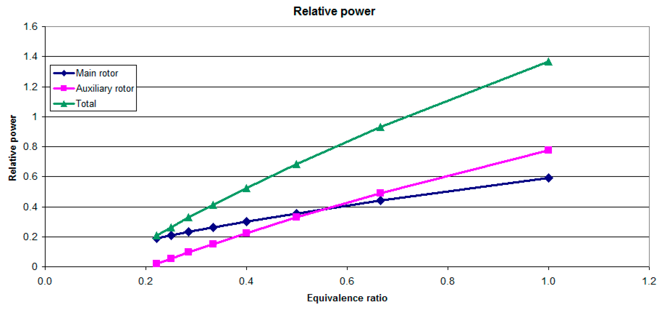
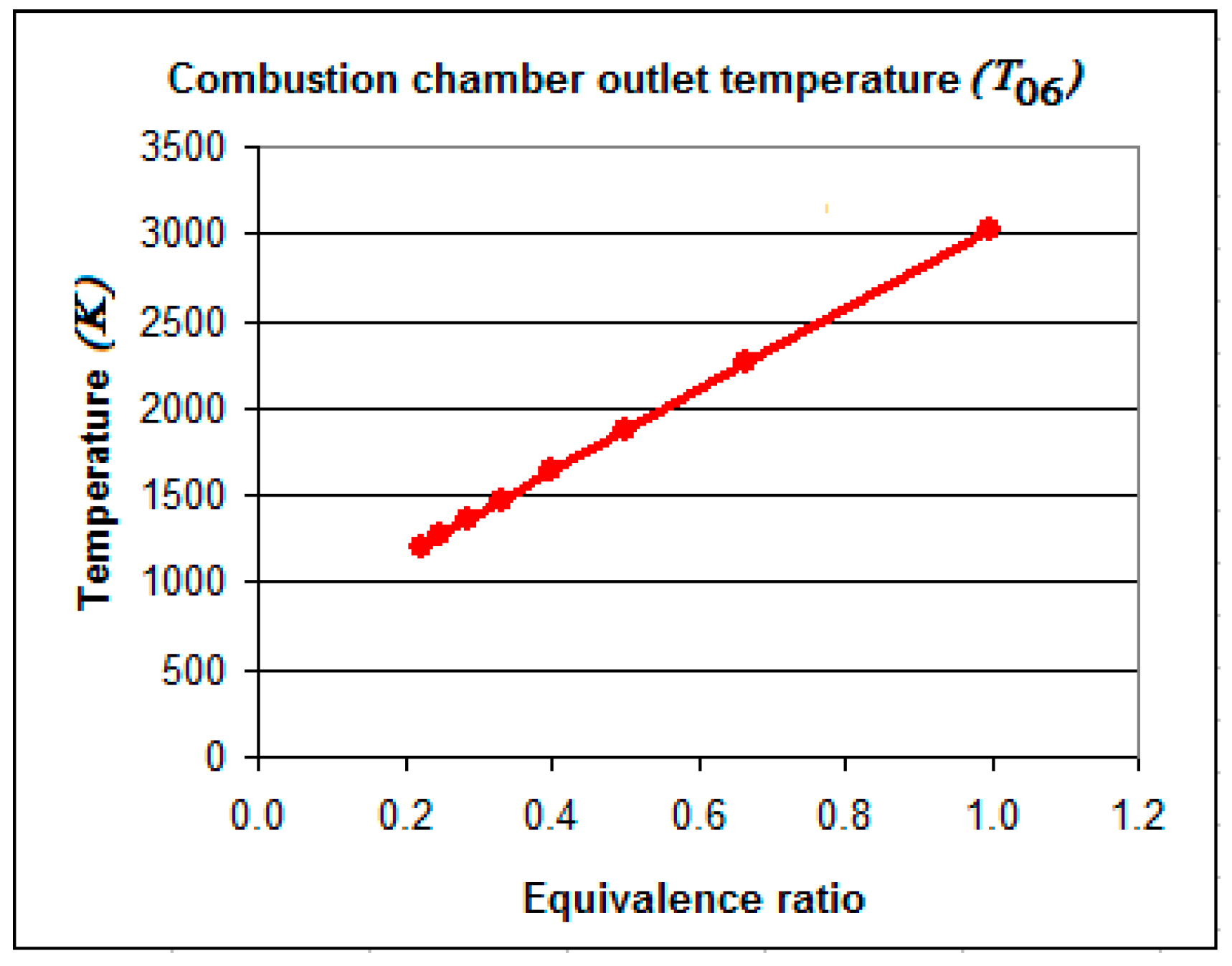
The variation of engine power, efficiency, and combustion chamber outlet temperature is presented as a function of the equivalence ratio representing the inversion of the excess air coefficient in Figure 11, Figure 12 and Figure 13 for the inlet Mach number 2.5.

Figure 11.
Estimated power of the main and auxiliary rotors and the total engine power at an inlet Mach number 2.5 in relation to the equivalence ratio.
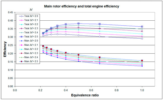
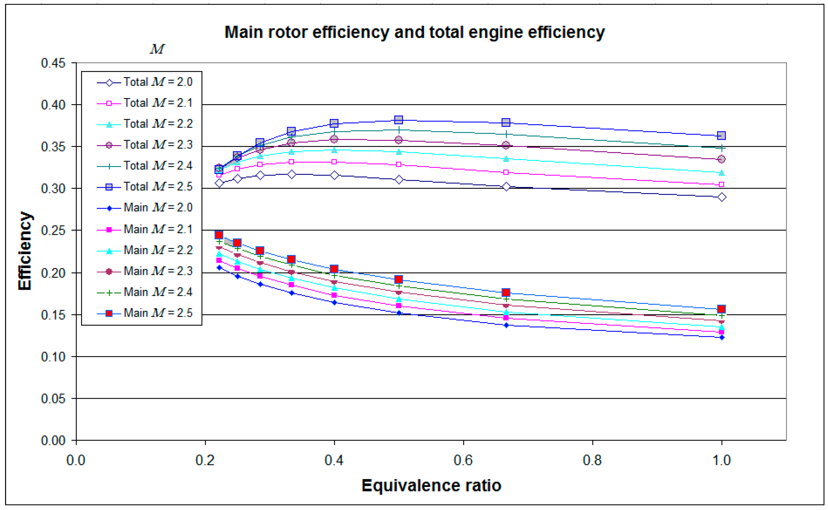
Figure 12.
Efficiency of the main rotor and double-rotor engines for the range of inlet Mach numbers as a function of the equivalence ratio.
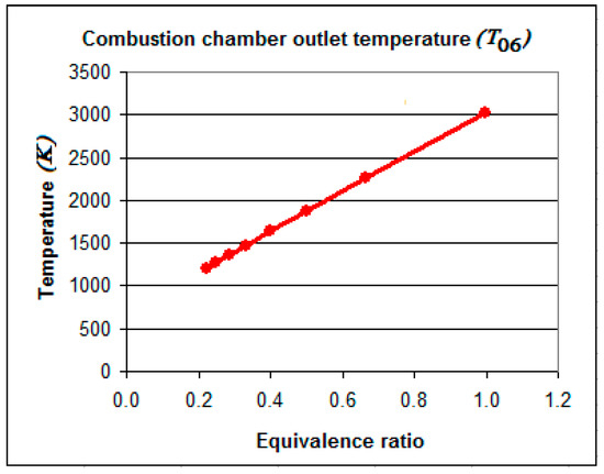
Figure 13.
Combustion chamber outlet temperature versus the equivalence ratio (inversion of excess air coefficient) at the inlet Mach number 2.5.
2.4.5. Reference Conditions
To present the obtained results in a universal way, three reference quantities were defined. These are the reference air flow rate, reference fuel mass flow rate, and reference power. As the reference flow of air flowing through the engine flow channel, the flow in a minimum cross-section of the inlet diffuser under specific ambient pressure and temperature was assumed. To determine this value, the following relationship was used:
where:
- is the determined value of the reference air mass flow rate (kg/s),
- 0.000179 m2 is the minimal cross-section of the inlet channel diffuser with a height of 1 cm,
- = 101,300 Pa is the assumed absolute flow reference pressure,
- = 288 K is the assumed reference flow temperature,
- = 1.4 is the adiabatic exponent of the air,
- = 1 is the assumed reference value of the flow Mach number in the inlet diffuser, and
- R = 287 J/(kg K) is the air gas constant.
Using the above formula and the assumed values, the reference air mass flow rate of the engine equipped with four stream channels with a height of 1 cm was 0.2725 kg/s. On this basis, the fuel mass flow rate at an equivalence ratio equal to 1 was calculated to be 0.01859 kg/s, while the reference power was defined as the fuel mass flow rate times the fuel LHV value (45,000 kJ/(kg K)), giving a value of 836.6 kW.
Some results of the investigation using the analytical model are presented in Figure 11, Figure 12 and Figure 13.
In Figure 11, an almost linear growth of the main rotor power, auxiliary rotor power, and engine total power can be observed with an increase of fuel in the combustion mixture (increasing equivalence ratio).
A low value of the equivalence ratio means a lean mixture (excess air coefficient equals to 4.5) and a high value means a rich stoichiometric mixture.
A rich mixture on the one hand gives higher power, but on the other hand, the combustion chamber outlet temperature is very high, as can be seen in Figure 13.
The amount of fuel used, as represented by the equivalence ratio, has an influence on the position of the normal shockwave in the insulator, whose effect is not taken into account in the simplified analytical model.
An almost linear increase of the generated power (see Figure 11) and combustion chamber outlet temperature (see Figure 13) can be observed in contrast to the decreasing efficiency of the main rotor operation and a strongly nonlinear variation of the double-rotor engine efficiency versus the equivalence ratio, as seen in Figure 12.
An addition of an auxiliary rotor dramatically increased the total engine power and total engine efficiency.
In Figure 12, a reduction of the main rotor efficiency with an increasing value of the equivalence ratio can be observed.
The theoretical contra-rotary ramjet engine configuration shows (see Figure 12) a much higher total efficiency over the main rotor efficiency, which can be treated as a single-rotor engine configuration. Also, the total power generated by the contra-rotary configuration (see Figure 11) is almost two times higher than in the single-rotor design.
The results of the analytical model have been used for the validation of the more sophisticated and more exact numerical model of the engine. It was used to establish the theoretical limits of the engine parameters.
3. Technical Realization
3.1. Rotary Ramjet Engine Idea
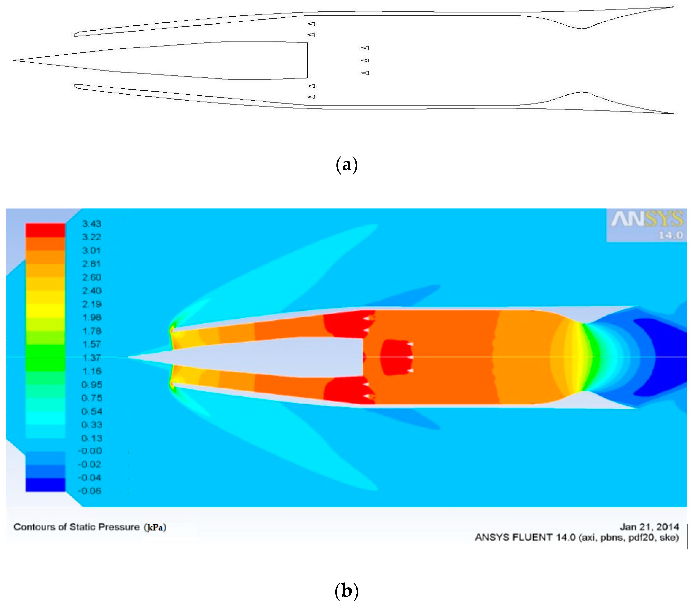
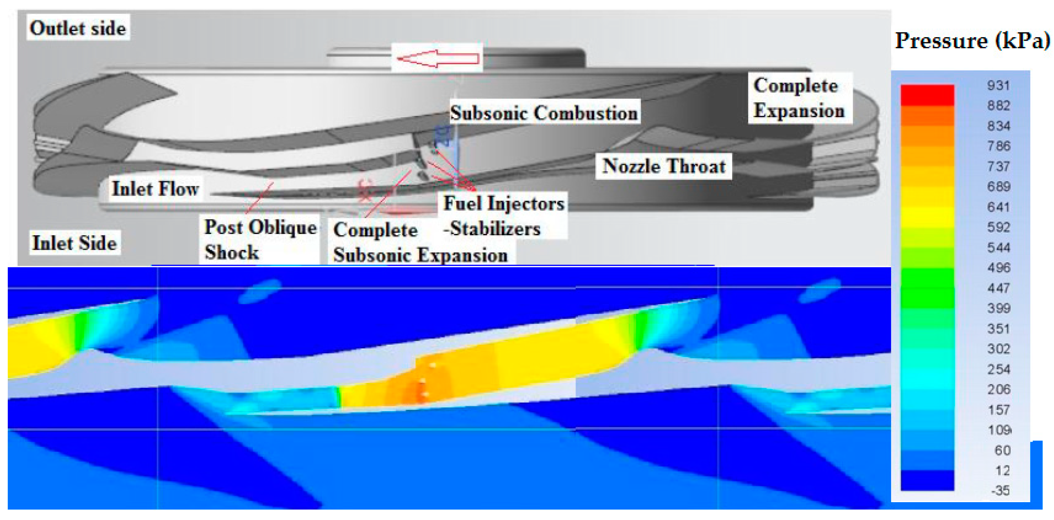
A technical solution for a single-rotor rotary ramjet engine is presented in Figure 14. It shows the channel outline of one of the four flow systems forming a rotary engine with shockwave compression and an example pressure distribution in the channels of this engine segment. In Figure 14, one can observe the existence of the oblique shockwave system due to the normal shockwave compressing the air in the inlet channel, followed by subsonic compression in the diffuser and an almost constant pressure zone corresponding to the combustion chamber area with fuel injectors and flame stabilizers, finished by the decompression process in the supersonic nozzle. The engine operation was considered for inlet Mach numbers between 2.0 and 2.5.

Figure 14.
Geometry of the channels of one of the four engine segments and an example pressure distribution in the engine channels (Pa).
Considering that the engine consisted of four channels, the power of the entire engine was close to 300 kW, with an efficiency of 16–18% [19].
The efficiency of the engine was not high, but it was comparable to the efficiency of a small turbine engine.
The performed calculations, using a three-dimensional model of the analyzed engine construction, indicated the existence of three-dimensional effects in the vicinity of the side walls of the main flow channel of the engine, while maintaining a flow structure at half the height of the channel that was identical to the two-dimensional solution, as shown in Figure 15b.
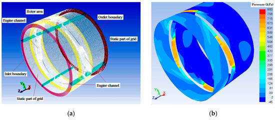
Figure 15.
(a) The discretizing grid in a three-dimensional model and (b) the pressure distribution in the middle plane of the 3-D engine channels [19] (at a radius of 0.3 m).
The pressure distribution shown in Figure 15b in the circumferential plane, placed at half of the engine channel height, coincided very well with the results of the two-dimensional solutions [19]. Considering the conclusions of the previous study [19], all analyses in recent studies were limited to a two-dimensional geometry.
3.2. Contra-Rotary Ramjet Engine Idea
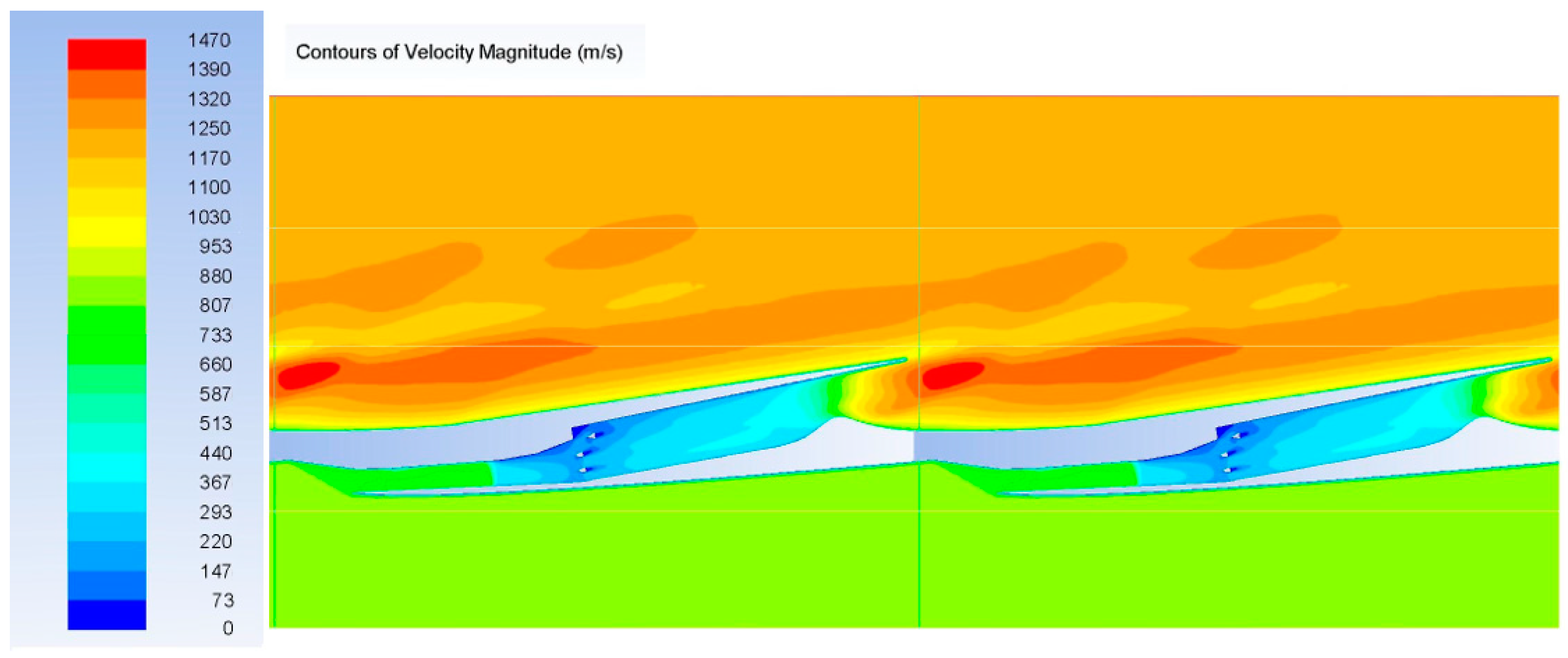
Analyzing the obtained velocity distributions of the exhaust gases leaving the exit nozzles of the single-rotor rotary engine, the existence of their large peripheral component (Figure 16) and the associated large losses of kinetic energy were noticed. Therefore, the possibility of using an additional rotor driven by the exhaust gases from the main rotor was considered and was the basis for a new solution.

Figure 16.
Distribution of the flow velocity (m/s) relative to the single-rotor engine (M = 2.5).
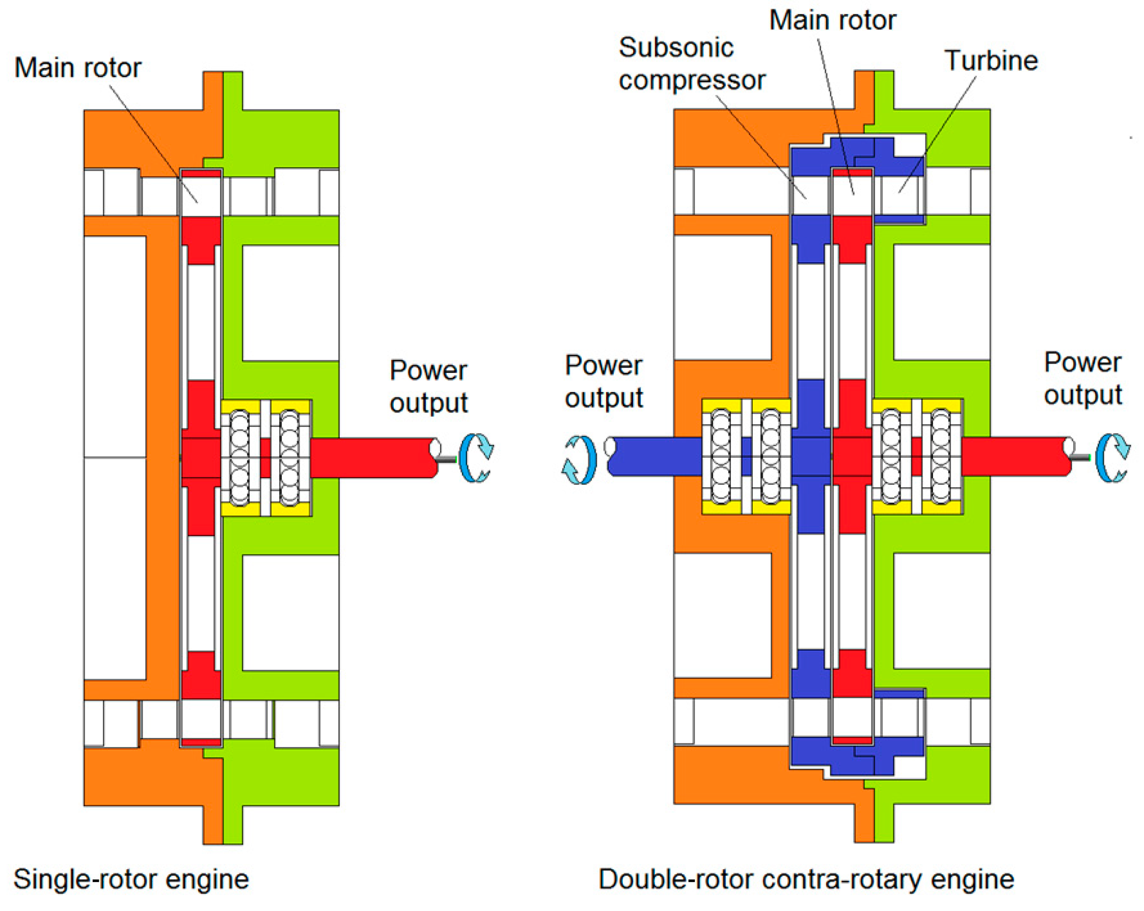
The disadvantages of the basic design solution of a single-rotor engine is the high linear velocity of the edges of the inlet engine channels located on the rotor perimeter, which are necessary to obtain supersonic speeds at the inlet. The high linear speed of the engine channels is associated with high loads from centrifugal forces and high rotor speeds, limiting the possibility of using ball or roller bearings. As the speed of air relative to the moving inlet is decisive, the possibility of using an additional rotor upstream of the inlet of the compressor, rotating in the opposite direction, causing the relative velocity at the inlet to the supersonic compressor to be the summed value of the speeds of both rotors, is proposed. It was assumed that the additional rotor will be driven by a turbine located downstream of the engine’s main rotor utilizing the exhaust gases. The discussed double-rotor engine scheme is shown in Figure 17.
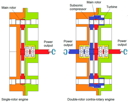
Figure 17.
Comparison of the one-shaft and two-shaft engine.
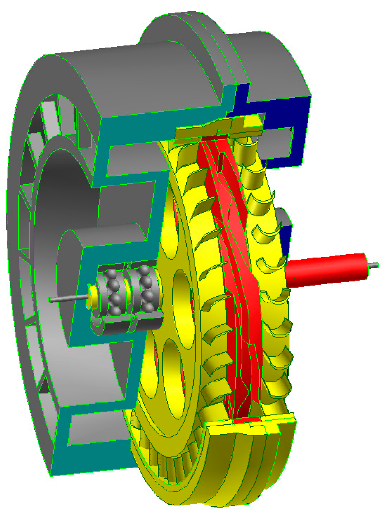
The 3-D diagram in Figure 18 illustrates the potential construction solution of the discussed engine.

Figure 18.
Visualization of a construction scheme for a double-rotor engine structure.
The auxiliary impeller with the pre-compressor was mechanically fastened with an external turbine that drove it outside the main rotor.
The use of two drive shafts rotating in opposite directions distinguished the proposed concept from existing ones. On the first shaft, an auxiliary system consisting of a subsonic compressor and an axial turbine were placed together, while on the second shaft, there was the main arrangement of the rotary jet engine channels. The main rotor of this engine was located between the axial blades of the compressor and the axial turbine of the auxiliary system. The rotors shown rotated in opposite directions to each other. This solution was intended to reduce the rotational speed of the rotors while maintaining a high relative speed of the air inflow at the inlet to the channels of the jet engine. Of course, from the turbine side, such a system reduced the relative speed of the exhaust gas flow to the auxiliary turbine blades. However, the calculations showed that the exhaust flow velocities from the main rotor nozzles were high enough to drive the auxiliary rotor that moved in the opposite direction. The lowering of the rotational speed of the engine shafts made possible the use of the rotors’ ball bearings. They do not require service, and the reduced revolution rate increases their service life. When using higher rotational speeds, compressing the air to a higher pressure using a subsonic axial compressor should positively affect the efficiency of the engine, assuming that mechanical energy is extracted from both shafts. It was assumed that the drive torques received from both shafts are transferred to two electric generators, whose rotations are controlled by electronic systems, and the generated electrical energy is stored in accumulators or supercapacitors.
The air entering the engine first flowed through a steering stage located in the housing, aimed at correcting the flow direction, such that the air flowing into the blades of the axial compressor moved in a direction parallel to the axis of the drive shafts. Then, the air flow was picked up by the subsonic compressor rotor vanes, which accelerated the working medium, thus transmitting mechanical energy to it, increasing the kinetic energy of the air. This system made it possible to achieve relative flow velocities of M = 2 and more at much lower rotational speeds of both rotors.
4. Numerical Model
Figure 19a shows the geometry of the subsonic compressor vanes, main rotor channels (supersonic compressor, insulator, combustion chamber, expansion nozzle), and turbine blades driving the subsonic compressor, with an example pressure distribution in the flow field areas depicted in Figure 19b.

Figure 19.
(a) Engine components’ geometry showing the subsonic compressor vanes, main rotor channels (supersonic compressor, insulator, combustion chamber, expansion nozzle), and turbine blades driving subsonic compressor; and (b) an example pressure distribution.
4.1. Fluid Flow and Combustion Models
The flow inside the engine, as well as outside of it, is assumed to be steady, turbulent, and compressible. In the case of ramjet engines, the compression process is performed around the inlet of the engine through an advanced system of shockwaves. In general, a sequence of oblique shockwaves has a relatively higher compression efficiency compared to a single normal shockwave due to the smaller growth of entropy in oblique shockwaves. The flow was described using averaged Navier-Stokes equations, supplemented by the k-ε turbulence model. Due to such a turbulence model being used, a wall function on the engine walls was used. This turbulence model was applied due to the requirements of the combustion model needing to be used simultaneously. After compression in the shockwave system, air at subsonic speed was transferred to the combustion chamber. Then, fuel was added to the compressed air. In the used combustion chamber embodiment, the injectors were a part of the flame stabilizers. The combustion mechanism was assumed to be of a diffusion type, and the combustion process was controlled by the turbulent diffusion of fuel and oxygen in the combustion zone. Under such assumptions, the non-premixed combustion model was used for the simulation of the combustion process in the engine combustion chamber. The applied model was based on several simplifying assumptions. These were: high speed combustion chemistry, equilibrium of the process, and control of the combustion process solely by turbulent diffusion of the fuel and oxidizer. This means that the level of turbulent diffusion had to be many times greater than the molecular diffusion of the individual components of the reactants. This reduced the large set of individual transport equations to a single transport equation of a mixture fraction. This is valid only in high turbulence areas. Such conditions exist in the considered combustion chamber. The influence of the turbulence on the combustion process was taken into account by the additional transport of the mixture fraction variation. This equation contains terms that depend on the local turbulence parameters, such as the turbulent kinetic energy (k) and the energy dissipation rate (ε).
In the full complex solution of the averaged Navier-Stokes equations, two transport equations for k and ε, along with two additional transport equations of two quantities, namely the mixture fraction and the variance of the mixture fraction, were solved. The additional set of transport equations of the two variables, mixture fraction and mixture fraction variation, consisted of the mixture fraction () and the mixture fraction variation ():
with model constants:
Due to the assumption of fast chemical reactions occurring during combustion, the process itself could be calculated (solved) independently of the flow process, forming a set of tables containing solutions (temperature, density, and fraction of individual components of the fuel) that were dependent on only two parameters: mixture fraction and mixture fraction variation.
Before finding the solution of the flow field with combustion, data sets describing all possible cases of combustion defined by mixture fraction and turbulence influence represented by the possible mixture fraction variation were defined in discrete form and later interpolated when finding the flow-field solution.
During simulation of the flow, the combustion process results, based on the local values of the mixture fraction and its variance, were retrieved from the prepared tables (see Figure 20).
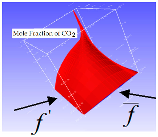
Figure 20.
An example of the distribution of a two-parameter function of carbon dioxide formation in a fuel combustion process.
4.2. Boundary Conditions
It was assumed that the engine operated under atmospheric conditions (pressure and temperature), sucking air from the environment and expelling exhaust gases to the atmosphere.
Therefore, at the inlet to the computational domain, the pressure inlet conditions were applied with an assumed turbulence level of 3% and a length scale value of 0.04 m.
At the outlet, the pressure outlet conditions were applied.
All simulated engine walls were treated as adiabatic with non-slip conditions.
4.3. Grid Sensitivity
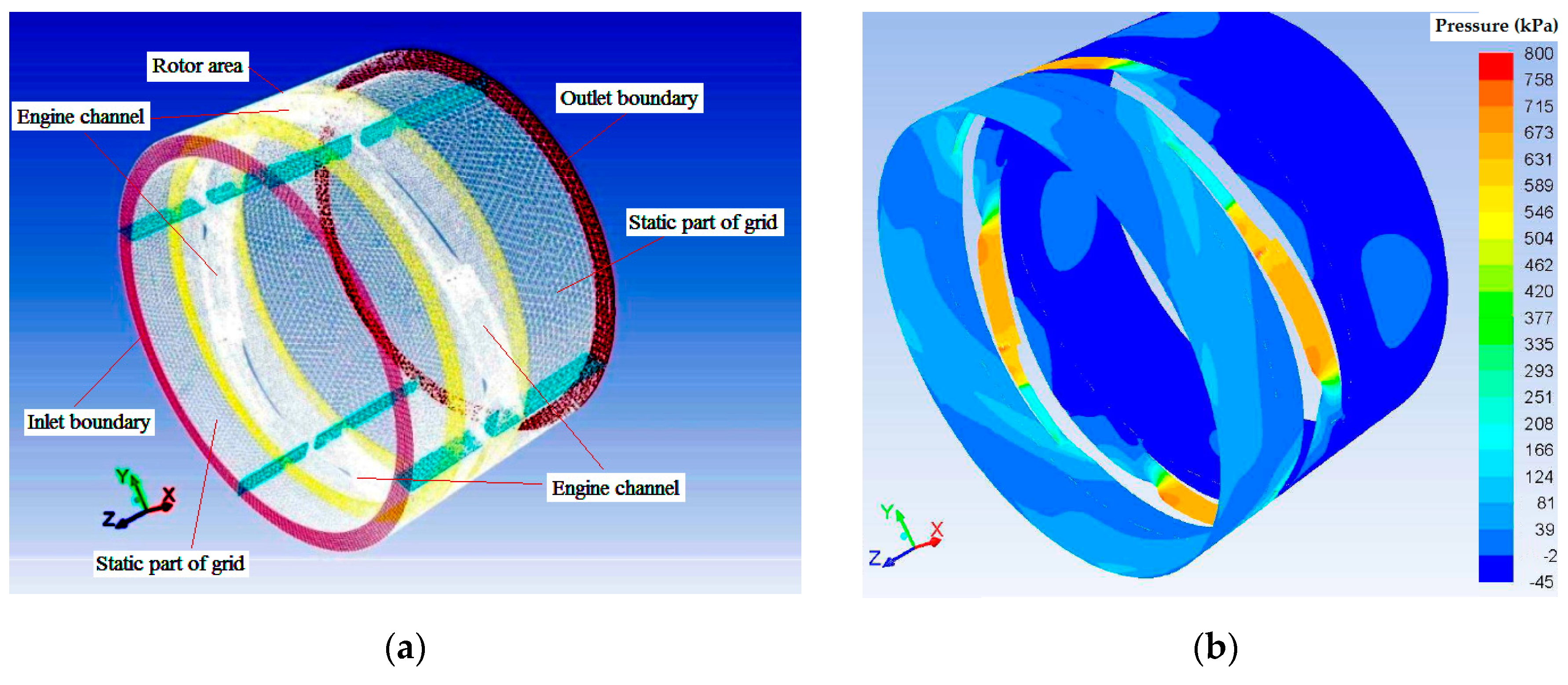
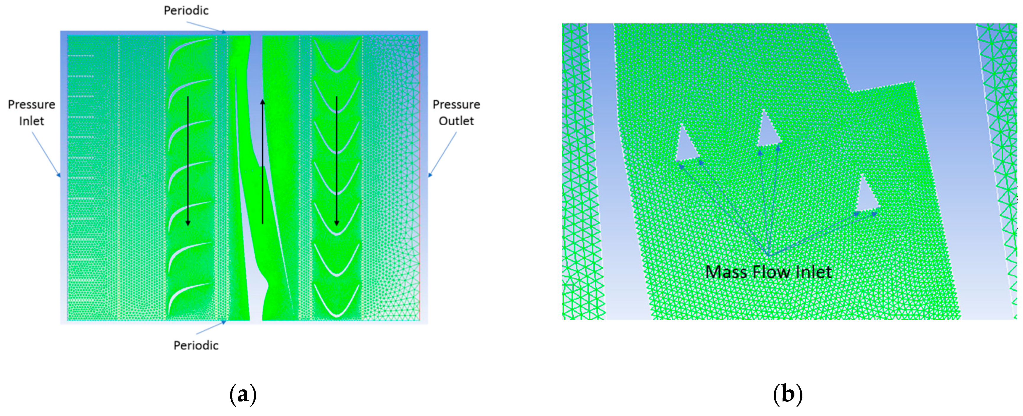
For numerical calculations, a two-dimensional calculation grid was used, which was a reflection of the engine’s circumference section. The current calculation area of the engine, along with the calculation grid, is shown in Figure 21a. Two mesh nets were used to test the effect of the mesh density, one with 130,000 elements and the other with 365,000 elements. The differences in the generated torques did not exceed 8%, and most calculations were made using a finer grid.
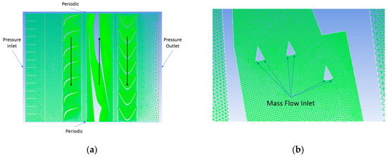
Figure 21.
(a) Grid used inside the computational domain and the applied boundary conditions. (b) Mesh used in the vicinity of the injectors and flame stabilizers, and boundary conditions representing fuel injectors.
The computational domain was divided into seven subdomains: four steady and three moving linearly. The moving frame technique was used for the simulation of the moving subdomains. In this technique, the grid in a subdomain was not moving and fluid motion was realized by the addition of motion velocity in all subdomain elements.
As shown in Figure 21a, the inlet and outlet subdomains were steady. The subdomain containing blades of the subsonic compressor and subdomain containing the action turbine blades had the same velocity direction and value because the subsonic compressor and turbine were mechanically connected. The domain containing the jet engine components (inlet channel, combustion chamber, and nozzle) had the opposite direction of motion.
To fulfill the requirements of the periodicity of the analyzed flow area, the periodic conditions were applied to the rest of the boundaries surrounding the computational domain.
The small part of combustion chamber presented in Figure 21b illustrates the system of flame stabilizers with fuel injectors, defined as boundary conditions of the mass flow inlet type.
The geometry of the turbine and compressor blades were not optimized in any way. The presented results were the first attempt to investigate the two contra-rotary rotor configuration of the ramjet engine. The aim of the investigation was to test the potential features of the new configuration.
The stoichiometric reference mass flow rate of the fuel was calculated to be 0.01859 kg/s.
To enable the transfer or comparison of the obtained results with the results obtained for the fuel rates of other geometries, the variation of the engine operating parameters were presented in relation to the equivalence ratio, which was defined as the stoichiometric air-fuel ratio to the current air–fuel ratio.
5. Calculation Results
The main purpose of using a double-shaft structure is to reduce the relatively high rotational speeds that the engine rotors would operate at. To this end, several numerical analyses were carried out for the case in which both shafts rotated at the same speed but in opposite directions. To obtain proper supersonic flow conditions in the channel of the jet engine, both rotors were rotated at 15,915 rpm. Using this assumption, a series of calculations for various values of fuel mass flow rates injected into the combustion chamber on the main rotor were made. The graphs below present the potential performance for the assumptions under consideration.
Practically, at constant rotor rotational speeds, the air mass flow rate is limited by the engine inlet geometry such that the addition of fuel not only increases the heat release and generated power, but also decreases the air-fuel ratio.
The above distribution of the ratio of mass air and fuel consumption (related to the reference conditions) presents the analyzed range of the engine working points under study. While maintaining constant speeds of both shafts, the air mass flow rate was kept constant; the only variable was the mass flow of fuel (in the range shown in the chart). The analyzed cases were characterized by the value of the mass ratio of air and fuel consumption in the range from 1.5 (for the highest analyzed fuel dose) up to 4.85 (for the lowest analyzed fuel dose) of the stoichiometric multiple of the mixture. These values show that the analyzed work points were characterized by a high excess of air, whose purpose was to cool the channel walls.
5.1. Comparison of the Overall Engine Characteristics
To show the advantages of the proposed contra-rotary ramjet engine (CORRE) idea, results obtained for a single-rotor and a double-rotor construction of the engine are presented in non-dimensional form using the reference parameters defined earlier.
The single-rotor engine (rotating at 27,000 rpm) performance was compared with the double-rotor engine (rotating at 16,000 rpm) performance.
As a reference, data values presented in Section 2.4 were applied.
In Figure 22, the air compression ratio realized by competing solutions at the same fuel consumptions is shown. It is clear that a similar or higher compression ratio can be obtained using the double rotor at only half the rotational speeds of the single rotor.
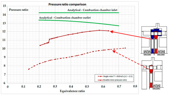
Figure 22.
The air compression ratio in terms of the amount of fuel supplied in one- and two-shaft engines.
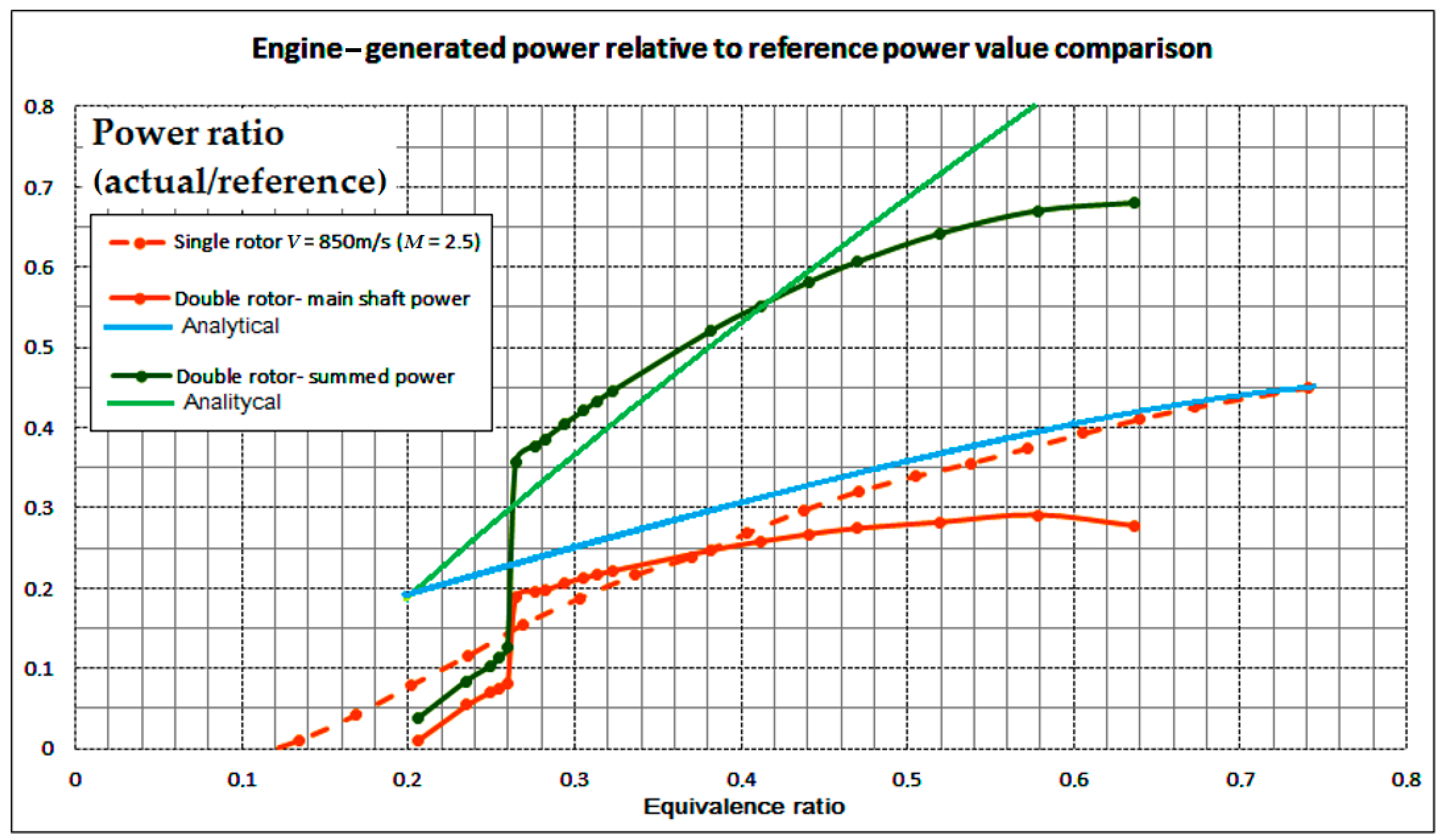
The graph presented in Figure 23 shows the power generated by both rotors as a function of the ratio of the current mass flow of fuel to the reference value. With the increase in the amount of injected fuel, the power values increased almost linearly. The power curve generated by the single-rotor solution was added for comparison. One can notice a 100% increase of power generated by the double-rotor engine version in the same range of fuel consumption due to the power generated by the auxiliary rotor.
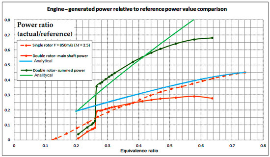
Figure 23.
Variability of the generated power by a single-rotor and double-rotor engine and the power generated by its rotors.
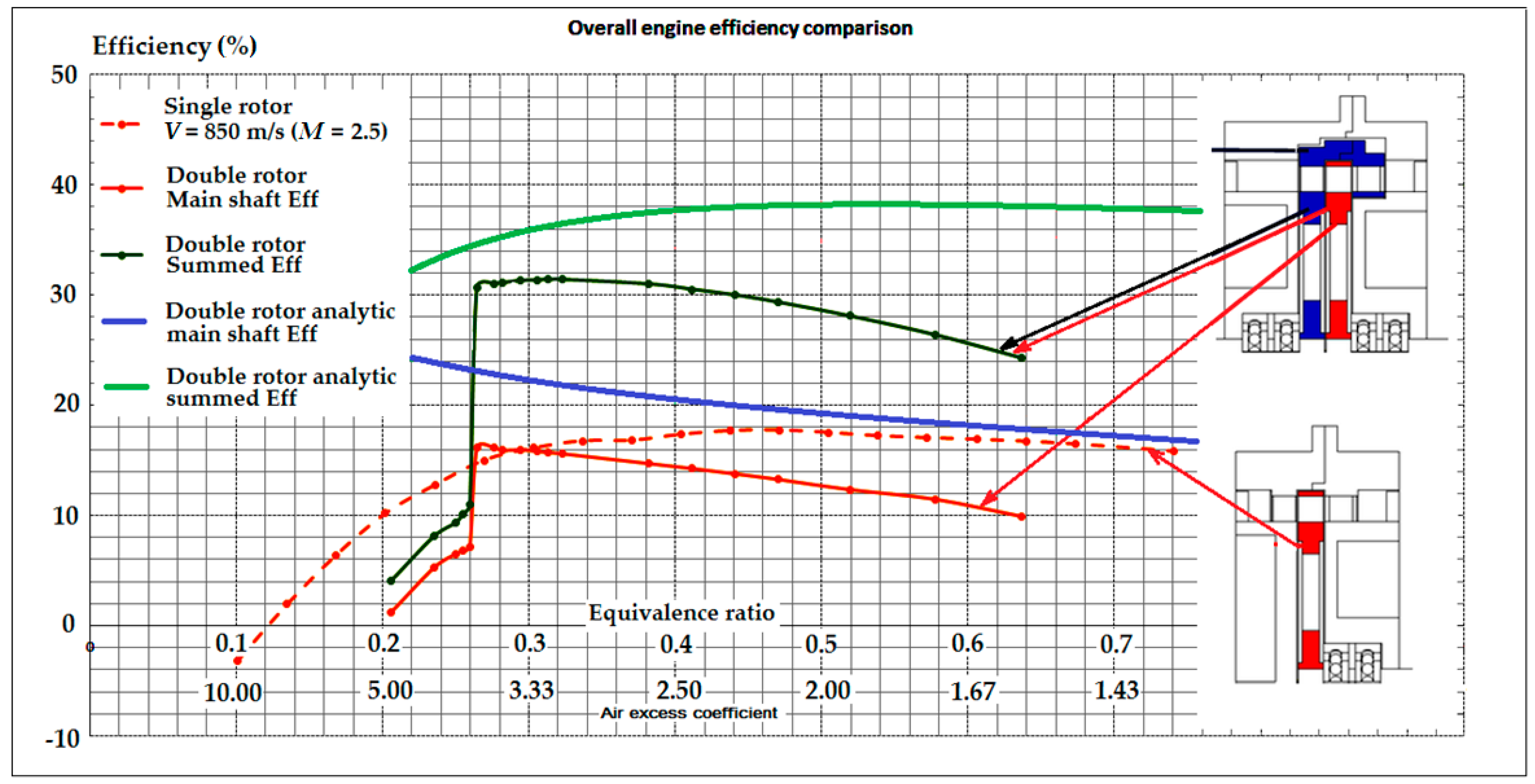
The graph in Figure 24 shows the efficiency of individual rotors as a function of the fuel mass flow rate in relation to its reference value. The aggregate (total) efficiency and the main shaft efficiency was defined as the ratio of the power generated by both shafts (or the main shaft itself) to the value of the power that should be generated due to the total combustion of a given amount of fuel used (Equations (29) and (30)).
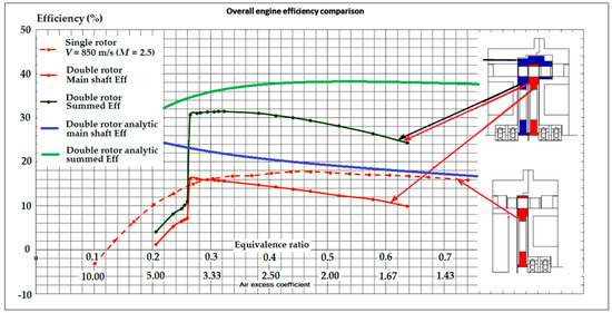
Figure 24.
Theoretical overall engine efficiency and efficiency of engine components compared with the efficiency obtained via numerical simulations.
The numerical model was limited to an inlet Mach number equal to 2.5 and a lean fuel–air mixture corresponding to combustion outlet temperatures lower than 2000 K and an excess air coefficient higher than 1.5, giving a chance to locally cool the engine channel walls and obtain the highest efficiency.
In Figure 24, the theoretical engine efficiency calculated by the analytical model is compared with the efficiency obtained by numerical simulations. One can notice that the single-rotor configuration was just below the theoretical limit and prospects of the development of such a construction is rather limited.
The contra-rotary configuration reached 80–85% of its theoretical limit and has the potential for further development.
In the area of the simulated low fuel mass flows, one can observe a characteristic efficiency jump resulting from the appropriate location of the normal shockwave inside the inlet of the channel on the main rotor. With the increase in the amount of fuel used, and thus the amount of heat supplied to the air flowing through the combustion chamber, the normal shockwave moved from the vicinity of the combustion chamber toward the initial inlet sections of the jet channel. Both rotors had interesting relationships. The main rotor achieved maximum efficiency values for relatively low fuel mass flow rates and began to lose it (almost linearly) with further increases of the amount of fuel used. The auxiliary rotor, in turn, achieved a maximum efficiency for larger quantities of fuel injected, although the optimal point of engine operation appeared at an excess air coefficient of 3.33 (equivalence ratio 0.3), where the total efficiency of the engine was then the highest and reached up to 31.4%.
The auxiliary rotor achieved only compression and expansion processes, even without any optimization of the compressor and turbine blades, and was characterized by a relatively high efficiency.
5.2. Details of the Flow Structure at the Operational Point
To understand the details of engine operation, some detailed information about the flow structure and flow parameters distribution are presented.
Knowing the optimal operating parameters and engine performance for equal rotor speeds, the flow conditions inside the engine were analyzed for this configuration.
The drawings presented in Figure 25 illustrate the contours of the static pressure inside the engine channels. The air entering the structure was pre-compressed by an axial compressor (minor change compared to the supersonic main rotor channels). It then flowed into the supersonic inlet channels where an oblique shockwave was generated, which was reflected several times inside the channel and ended with a perpendicular (normal) shockwave with the subsonic flow moving downstream to the combustion chamber. The flowing air was slowed down in the diffuser channel, with a simultaneous increase in the static pressure. Inside the combustion chamber, the exhaust gas pressure decreased slightly, and then, flowing through the convergent-divergent nozzle, the combustion products were rapidly accelerated to high speeds, while the static pressure dropped. In the last part of the engine, the moving fumes flowed through the area of the axial turbine of the auxiliary rotor. In this sector, the exhaust gas transferred its energy to the turbine, accelerating it to a sufficiently high rotational speed. The exhaust gas pressure leaving the engine was comparable to the ambient pressure, which minimized the flow losses resulting from the difference in pressure between the environment and the exhaust gases.
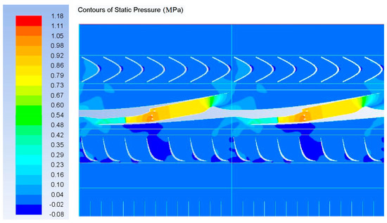
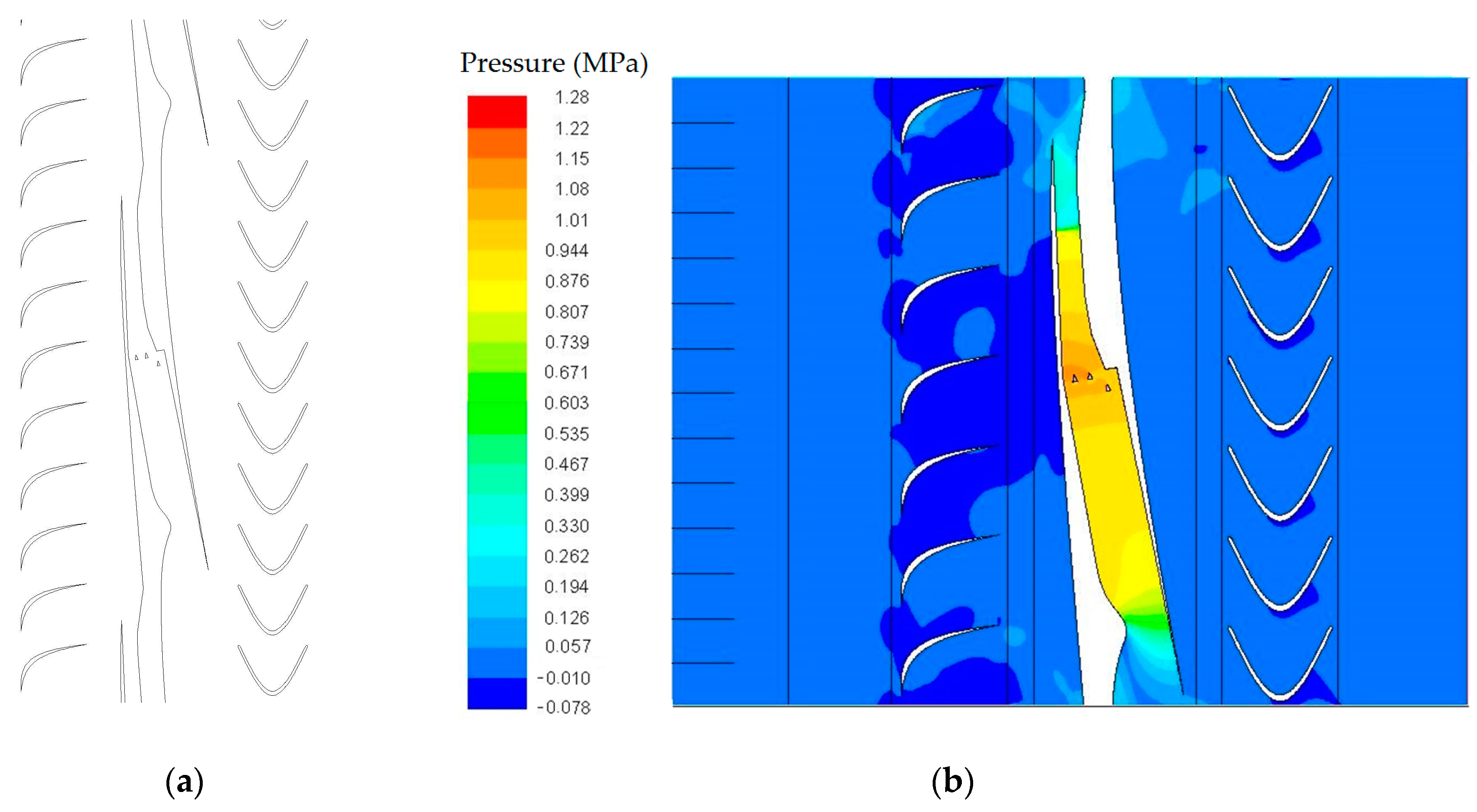
Figure 25.
Contours of the pressure distribution inside the engine channels.
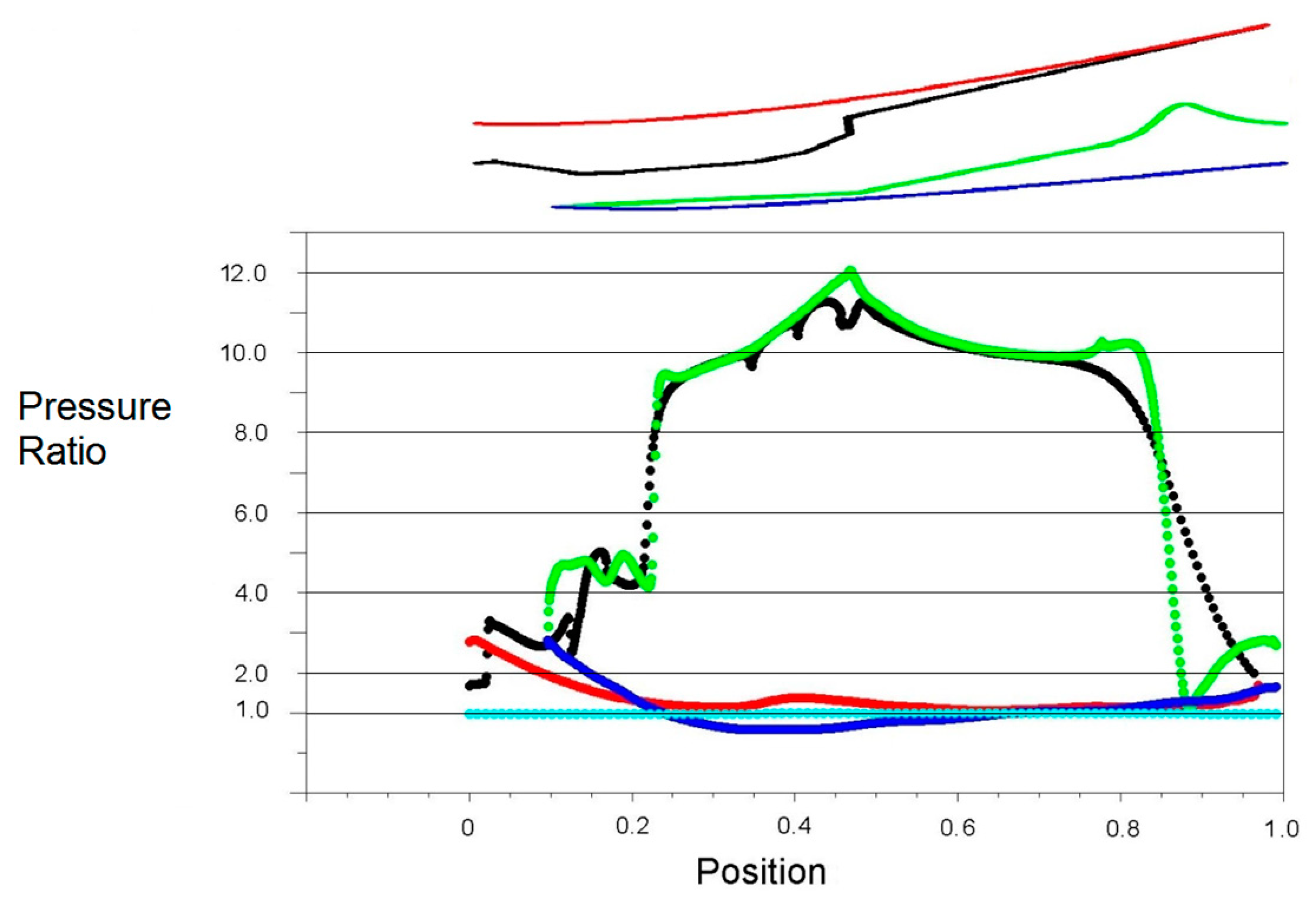
The graph presented in Figure 26 shows the distribution of the static pressure ratio at the engine’s main rotor channel walls. The shape of the analyzed engine elements is presented just above the graph in Figure 26. The color of each line corresponds to the color of the data in the graph. Only the data set in light blue did not have its equivalent on the sketch of the channel; it is the pressure value at the inlet to the calculated area (mean value of the atmospheric pressure, treated as a reference). Based on the above specification, it was easy to determine the total compression of the engine, as well as the compression of individual elements. The air flowing into the stream passages already had an elevated pressure relative to the inlet pressure (it was about three times higher than the reference value); this was a direct effect of the axial compressor placed in front of the ramjet rotor. Then, due to the interaction of the shockwave system and the diffuser, the flow pressure increased dramatically to a value about 12 times higher than the atmospheric pressure. Therefore, it can be stated that the total compression ratio of the engine could reach values of 12 under the given conditions.

Figure 26.
Pressure distribution on the walls of the engine channels.
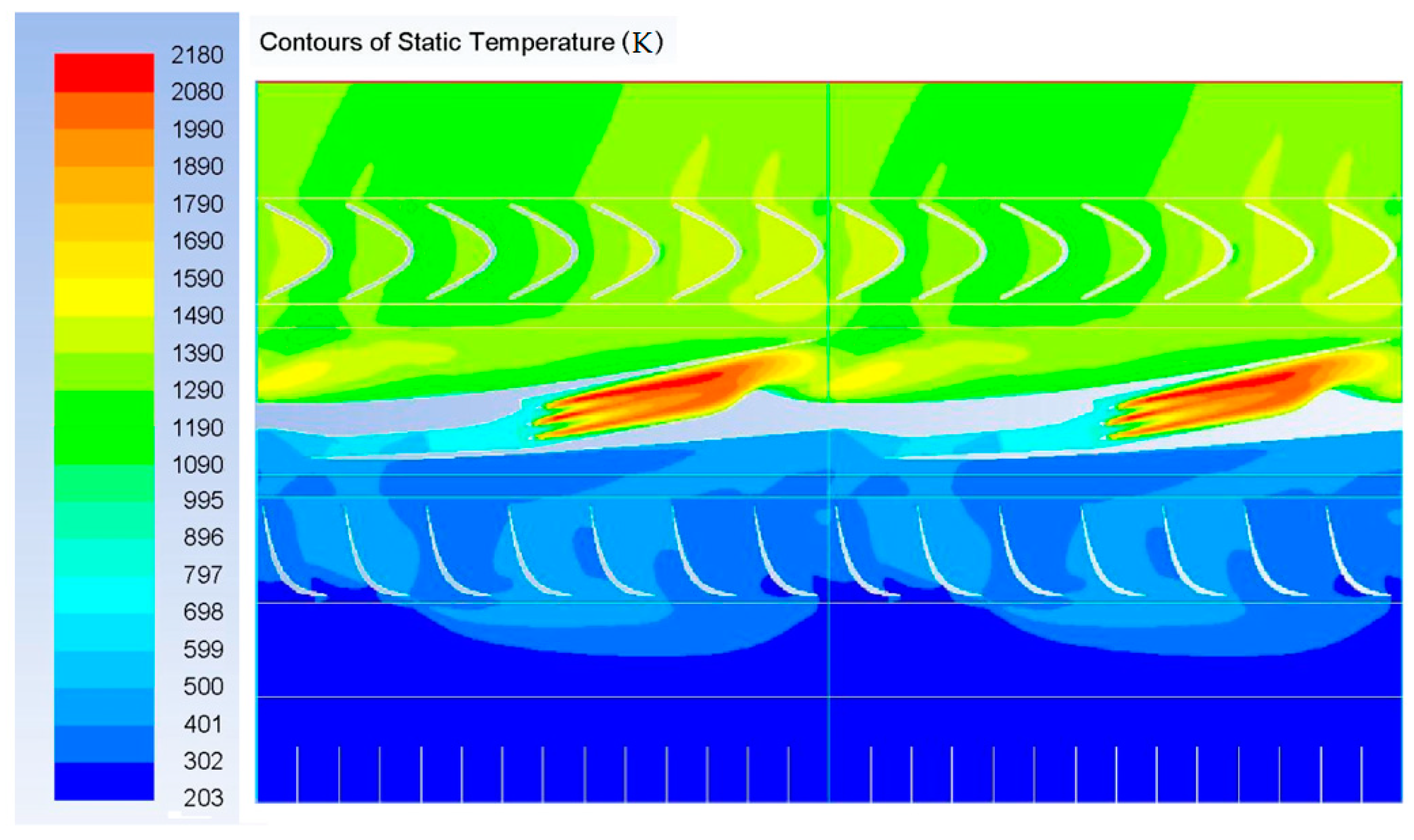
The temperature distributions shown in Figure 27 and Figure 28 confirm the areas in which the flow pressure increased (axial compressor and the area of the diffuser generating the shockwave system). The area of maximum temperature was inside the combustion chamber and the temperature of the exhaust gases successively decreased, moving within the convergent-divergent nozzle, and in the area of the axial turbine.

Figure 27.
Contours of static temperature inside the engine channels.
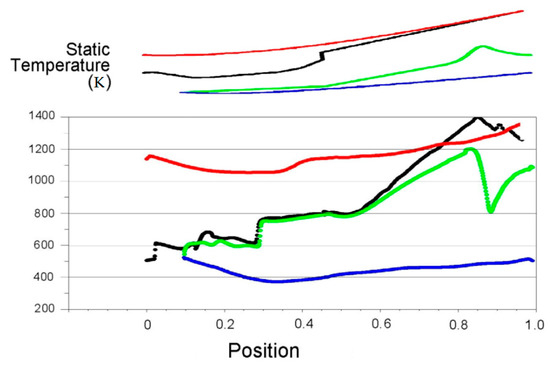
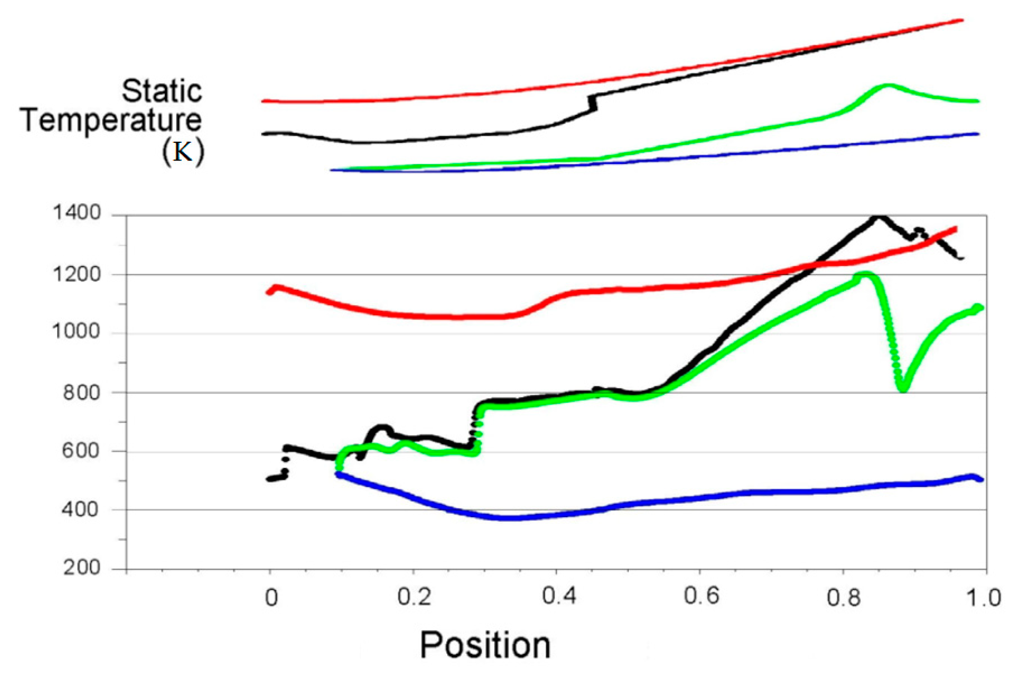
Figure 28.
Static temperature distribution on the walls of the engine channels.
In order to accurately analyze the operation of the flow channels placed on the main shaft, the above temperature diagram was made for the characteristic internal and external walls of one of the stream channels, with an additional sketch of the geometry of the analyzed surfaces, aimed at facilitating the monitoring of individual changes. In the case of the external walls, their temperature did not change significantly; however, minor fluctuations in the temperature of these surfaces were found. The temperature distributions of the internal walls were much more interesting. To a large extent, they reflected the static pressure distributions. In the inlet area and the inlet diffuser, temperature jumps were noticeable due to the shockwaves present in this section (resulting in sudden pressure surges). The combustion chamber section was characterized by the largest increase in the temperature of the walls due to the combustion process. In the convergent-divergent nozzle, as a result of the rapid flue gas expansion process, a drop in the temperature of the walls was noticeable.
The numerical analyses carried out made it possible to determine the optimal parameters of the engine’s operation, enabling a high level of efficiency. Table 1 presents the optimal working parameters and the performance of the current version of the engine, which was equipped with 1 cm high channels.

Table 1.
Estimated engine parameters.
6. Conclusions
Based on the presented results, it can be concluded that the concept of a two-shaft rotary shockwave compression engine (contra-rotary ramjet engine) was technically feasible, yielding relatively high levels of efficiency.
The main findings of the analyzed study were:
- The presented numerical model indicated a good match with the analytical model.
- The geometry of the flow channels, as well as the use of a second rotary shaft with an axial compressor and turbine, had an important effect on the operational parameters of the engine.
- The implementation of a double-rotor design made it possible to reduce the engine shaft speeds from 28,000 rpm (tip speed 840 m/s) to 16,000 rpm (tip speed 540 m/s), keeping the flow characteristics inside the ramjet channels intact.
- The modifications considered in this study (using a second rotary shaft with an axial compressor and turbine, as well as minor modifications of the jet channels) made it possible to achieve a significant improvement in engine performance. Assuming that power would be received from both shafts, the channels generated the total power at an efficiency of 31.4%.
The final version of the presented structure was the result of a simple optimization process of flow channels of the main rotor, based on the analysis of characteristic flow parameter visualizations. The geometry of the turbine and compressor blades was not optimized in any way. The presented results were the first attempt to investigate the two contra-rotary rotor configuration of the ramjet engine. The aim of the investigation was to test the potential features of the new configuration.
To summarize, further development and improvement of engine performance is possible. Despite using approximated assumptions (adiabatic walls), the results of this analysis are very promising, while at the same time, not precluding further development, which may result in further improvements of the working parameters of the rotational supersonic engine.
The analytical model provided information on the theoretical limits of the considered solution. The single-rotor design almost reached the theoretical, not very high performance limit, which means there are no great prospects for further improvement.
The design of the contra-rotary ramjet engine has, on the one hand, a relatively high theoretical performance limit, and on the other hand, the efficiency of the existing technical solution simulated using CFD was relatively high but was still far from the theoretical limit. Therefore, there are good prospects for further improvement.
However, the numerical calculations in this study concerned a hydrocarbon fuel. Hydrogen could also be used as a fuel in the engine under analysis.
The most likely application of the proposed CORRE engine seems to be a hybrid car range extender.
7. Patents
A patent claim for the presented idea of the contra-rotary ramjet engine has been submitted.
Patent application nr p. 424280. 16 January 2018, “Usprawnienie konstrukcji rotacyjnego silnika cieplnego wykorzystującego sprężanie falami uderzeniowymi” (“Improving the design of a rotary heat engine using shock wave compression”), authors: Janusz Piechna, Tomasz Laube.
Author Contributions
Conceptualization, J.P.; methodology, T.L. and J.P.; software, T.L.; validation, J.P. and T.L.; formal analysis, J.P.; investigation, T.L. and J.P.; writing—original draft preparation, J.P. and T.L.; writing—review and editing, J.P. and T.L.; visualization, J.P. and T.L.; supervision, J.P. All authors have read and agreed to the published version of the manuscript.
Funding
This research received no external funding.
Conflicts of Interest
The authors declare no conflict of interest.
References
- Flight. 2 November 1956, pp. 724–725, (might be in maintenance). Available online: https://www.flightglobal.com/flight-international/flight-magazine-archive (accessed on 11 November 2019).
- Decker, W. Practical Ramjet Design; Decker Engine Works: Virginia, VA, USA, 1954. [Google Scholar]
- Kendrick, D.W.; Chenevert, B.C.; Trueblood, B.; Tonouchi, J.; Lawlor, S.P.; Steele, R. Combustion System Development for the Ramgen Engine. J. Eng. Gas Turbines Power 2003, 125, 885–894. [Google Scholar] [CrossRef]
- Wang, Y.; Meng, X. Dynamical stress analysis of ram-compressed rotor of rotated ramjet. J. Nanchang Inst. Aeronaut. Technol. (Nat. Sci.) 2006, 20, 13–17. [Google Scholar]
- Lawlor, S.P.; Hinkey, J.B.; Mackin, S.G.; Henderson, S.; Bucher, J.; Brown, P.M.; Pudupatty, R. Supersonic Compression Stage Design & Test Results. In Proceedings of the ASME 2004 International Mechanical Engineering Congress and Exposition, Anaheim, CA, USA, 13–19 November 2004; ASME: New York, NY, USA, 2004. [Google Scholar]
- Lupkes, K. Ramgen Supersonic Shock Wave Compression and Engine Technology. In Proceedings of the 2012 NETL CO2 Capure Technology Meeting Sheraton Station Square, Pittsburgh, PA, USA, 11 July 2012. [Google Scholar]
- Wang, Y.; Zhao, X.L.; Xu, J.Z.; Ang, H.S. Numerical Simulation of Non-Reactive Flow Field for Rotating Ramjet Ram-Compressed Rotor Disc Cavity. J. Nanjing Univ. Aeronaut. Astronaut. 2006, 2, 143–147. [Google Scholar]
- Yu, D.; He, B.; Lv, X. Characteristics analysis of pressure ratios for rotated ramjet inlets. J. Propul. Technol. 2008, 3, 329–333. [Google Scholar]
- Steele, R.; Baldwin, P.; Kesseli, J. Insertion of shock wave compression technology into micro turbines for increased efficiency and reduced costs. In Proceedings of the ASME Turbo Expo 2005: Power for Land, Sea and Air, Reno, Nevada, USA, 6–9 June 2005; ASME: New York, NY, USA, 2005. [Google Scholar]
- Grosvenor, A.D.; Taylor, D.A.; Bucher, J.R.; Aarnio, M.J.; Brown, P.M.; Draper, R.D.; Lawlor, S.P. Measured and predicted performance of a high pressure ratio supersonic compressor rotor. In Proceedings of the ASME Turbo Expo 2008: Power for Land, Sea and Air, Berlin, Germany, 9–13 June 2008; ASME: New York, NY, USA, 2008. [Google Scholar]
- Picard, M.; Plante, J.-S.; Rancourt, D. Rim-Rotor Rotary Ramjet Engine (R4E): Design and Experimental Validation of a Proof-of-Concept Prototype. In Proceedings of the 20th ISABE International Symposium, Gothenburg, Sweden, 12–16 September 2011. [Google Scholar]
- Madasamy, K.S.; Yed Mohammed, P. Jeevanantham, Ramjet Engine for Power Generation. J. Basic Appl. Eng. Res. 2014, 1, 84–87. [Google Scholar]
- Brouillette, M.; Picard, M.; Rancourt, D.; Plante, J.-S. Shock-Induced Combustion and Its Applications to Power and Thrust Generation. In 30th International Symposium on Shock Waves 1; Springer International Publishing: New York, NY, USA, 2017; Volume 1, pp. 53–58. [Google Scholar]
- Rancourt, D.; Picard, M.; Denninger, M.; Chen, J.-S.J.; Yousefpour, A. Rim-Rotor Rotary Ramjet Engine, Part 1: Structural Design and Experimental Validation. J. Propul. Power 2012, 28, 1293–1303. [Google Scholar] [CrossRef]
- Picard, M.; Rancourt, D.; Plante, J.S.; Brouillette, M. High-g Field Combustor of a Rim–Rotor Rotary Ramjet Engine. AIAA J. 2014, 52, 1024–1034. [Google Scholar] [CrossRef]
- Dahm, W.J.A.; Lapsa, A.P.; Hamlington, P.E. Inside-Out Rotary Ramjet Turbogenerator. In Proceedings of the AIAA 2006-4169 4th International Energy Conversion Engineering Conference and Exhibit (IECEC), San Diego, CA, USA, 26–29 June 2006. [Google Scholar]
- Wang, Y.; Du, J.-Y.; Zhou, X.-L.; Xu, J.-Z. Analyse of RAM- Compressed for Rotating Ramjet. J. Eng. Thermophys. 2006, 6, 933–936. [Google Scholar]
- Zhang, G.; Liu, Z.; Kang, W.; Liu, Z.; Xin, T. Nonlinear dynamic characteristics of rotating ramjet rotor supported by hybrid gas bearing. Proc. Inst. Mech. Eng. Part G J. Aerosp. Eng. 2012, 228, 115–136. [Google Scholar] [CrossRef]
- Laube, T.; Piechna, J.; Müller, N. Rotary Ramjet Engine—Numerical analysis of aerodynamics and combustion. Arch. Combust. 2014, 34, 129–154. [Google Scholar]
- Liepmann, H.W.; Roshko, A. Elements of Gasdynamics; Wiley: Hoboken, NJ, USA, 1957; pp. 84–93. [Google Scholar]
- Anderson, J.D., Jr. Fundamentals of Aerodynamics; McGraw-Hill: New York, NY, USA, 1984; pp. 347–359. [Google Scholar]
- Kuethe, A.M.; Chow, C.Y. Foundation of Aerodynamics: Bases of Aerodynamic Design, 4th ed.; Wiley: Hoboken, NJ, USA, 1986; pp. 225–229. [Google Scholar]
- Szumowski, A.; Selerowicz, W.; Piechna, J. Dynamika Gazów; Wydawnictwa Politechniki Warszawskiej: Warsaw, Poland, 1988. [Google Scholar]
- Penkner, A.; Jeschke, P. Analytical Rayleigh pressure loss model for high-swirl combustion in a rotating combustion chamber. CEAS Aeronaut. J. 2015, 6, 613–625. [Google Scholar] [CrossRef]
- Penkner, A.; Jeschke, P. Advanced Rayleigh Pressure Loss Model for High-Swirl Combustion in a Rotating Combustion Chamber. J. Eng. Gas Turbines Power 2016, 138, 021502. [Google Scholar] [CrossRef]


© 2019 by the authors. Licensee MDPI, Basel, Switzerland. This article is an open access article distributed under the terms and conditions of the Creative Commons Attribution (CC BY) license (http://creativecommons.org/licenses/by/4.0/).