Abstract
Smoke control is a crucial issue in a long-distance subway tunnel fire, and a two-point extraction ventilation system is an effective way to solve this problem, due to the characteristics of controlling the smoke in a limited area and removing high-temperature and toxic smoke in time. In this study, the ceiling temperature distribution and the critical exhaust volumetric flow rate to control the smoke in the zone between two extraction vents were investigated in a long-distance subway tunnel fire with a two-point extraction ventilation system. Experiments were carried out in a 1/20 reduced-scale tunnel model based on Froude modeling. Factors, including the heat release rate (HRR), the extraction vent length, the internal distance between two extraction vents and exhaust volumetric flow rate, were studied. Smoke temperature below the ceiling, exhaust volumetric flow rate and smoke spreading configurations were measured. The ceiling temperature distribution was analyzed. Meanwhile, an empirical equation was developed to predict the critical exhaust volumetric flow rate based on the one-dimensional theory, experimental phenomenon and the analysis of forces acting at the smoke underneath the extraction vent. The coefficients in the empirical equation were determined by experimental data. Compared with the experimental results, the developed empirical equation can predict the critical exhaust volumetric flow rate well. Research outcomes in this study will be beneficial to the design and application of two-point extraction ventilation system for a long-distance subway tunnel fire.
1. Introduction
Recently, there is fast subway tunnel construction to meet the rapidly growing demand of urban transportation in China. Unfortunately, a fire occurrence in a tunnel can result in a serious accident. For example, the Yanhou tunnel fire in China in 2014 killed 31 people [1]. Statistics have shown that smoke is the fatal factor in the event of fires, and approximately 85% of the victims die owing to the inhalation of hot and toxic smoke [2]. Therefore, it is very important to control the smoke to ensure passenger safety in tunnel fires.
Ventilation is essential to ensure a safe evacuation environment when hazards occur in the underground space [3,4]. In tunnel fires, the longitudinal ventilation system has been widely used to control smoke over the past years, which can prevent the smoke from spreading upstream in tunnel fires. Studies of tunnel fires with longitudinal ventilation mainly focused on the critical velocity, the back-layering length and the maximum temperature [5,6,7,8,9,10,11]. However, with the fast development of urban subway in China, many long-distance subway tunnels with a length of more than 3 km have been constructed. As the minimum departure interval of trains is only 2 min, two or more trains are likely to appear simultaneously in a long-distance tunnel. If there is a train fire and the longitudinal ventilation is used as shown in Figure 1, smoke of the burning train may spread to the following train, which is dangerous for the passengers of the following train.
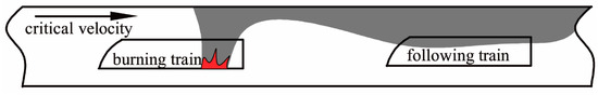
Figure 1.
Schematic diagram of longitudinal ventilation.
According to the above analysis, a longitudinal ventilation system is not appropriate for long-distance subway tunnel fires. In this case, a two-point extraction ventilation system will be considered as an alternative. When a fire occurs in the long-distance subway tunnel, two extraction vents mounted on the ceiling near the fire are opened automatically. Exhaust fans in both shafts are started up to discharge the smoke from the tunnel, as shown in Figure 2. This ventilation mode [12] can control the smoke within a certain zone to prevent the smoke spreading from the burning train to the following train in long-distance subway tunnel fires.
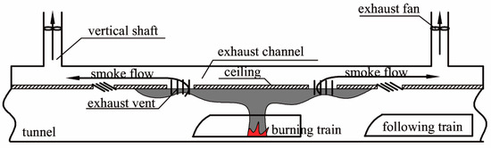
Figure 2.
Schematic diagram of two-point extraction ventilation.
In recent years, a few studies were conducted to investigate the point extraction ventilation system in tunnel fires. Vauquelin and Telle carried out a series of experiments using a gas mixture of helium and air as the fire source in a 1/20 isothermal model scale test rig to investigate the efficiency of a two-point extraction system, and the concept of confinement velocity was proposed [13]. Lin and Chuah investigated single-point and multi-point extraction ventilation using numerical simulations. It was found that the increase of the extraction vent number did not have significant influence on the efficiency of smoke exhaust when there were more than three exhaust vents [14]. Ingason and Li conducted model experiments to investigate the back-layering length and the ceiling temperature distribution with single and two-point extraction ventilation systems under different exhaust volumetric flow rates, and a model of back-layering length was developed as well [15]. Zhu et al. studied the effects of distances between extraction vents, geometry of extraction vent and shape of extraction vent on the efficiency of extraction system based on numerical simulations [16]. Mei et al. investigated the characteristics of smoke layer thickness experimentally, and concluded that the ratio of smoke layer depth to the clear height decreased with the increasing number of point extraction opening [17]. Tang et al. investigated the effects of burner size and exhaust velocity on the maximum temperature based on reduced-scale experiments. A model of maximum temperature by theoretical analysis and experimental results was derived [18]. In addition, some researchers have investigated longitudinal ventilation combined with the point extraction system. Hu et al. [19] and Chen et al. [20] investigated the back-layering length and the temperature decay factor using reduced-scale experiments, and a new model was developed to predict the back-layering length and temperature decay factor based on previous model. Tanaka et al. [21] put forward a theoretical model to predict the smoke layer thickness and the back-layering length based on theoretical analysis and experimental results. It was found that the effect of exhaust mass flow rate on heat release rate (HRR) was limited.
In summary, previous studies of point extraction ventilation in tunnel fires mainly focused on the issues including the efficiency of point extraction ventilation, the smoke layer thickness, the maximum temperature and the back-layering length. In addition, they only considered the exhaust volumetric flow rate as a variable. Very few studies were carried out to determine the appropriate value of the exhaust volumetric flow rate to control the smoke flow within an acceptable zone and predict it through theoretical model in tunnel fires using two-point extraction ventilation system. The principle of an effective two-point extraction ventilation system is to use sufficient exhaust volumetric flow rate to control the smoke in an acceptable zone. If the exhaust volumetric flow rate is not enough, part of the smoke is exhausted through the two extraction vents near the fire source, while the remained smoke will spread downstream of the extraction vents as shown in Figure 3a. This will damage the passenger safety. To better ensure the passenger safety in tunnel fires with two-point extraction ventilation system, a critical exhaust volumetric flow rate can be found, which is defined as the minimum exhaust volumetric flow rate to control the smoke to the zone between two extraction vents, as shown in Figure 3b.
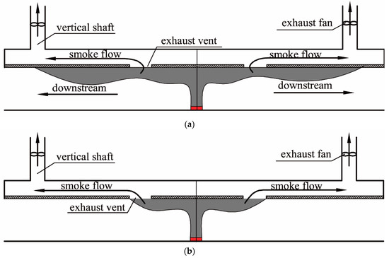
Figure 3.
Smoke diffusion under different exhaust volumetric flow rates in tunnel. (a)small exhaust volumetric flow rate; (b) critical exhaust volumetric flow rate.
In this study, a series of burning experiments were conducted in a 1/20 reduced-scale tunnel model using Froude modeling to investigate the ceiling temperature distribution and critical exhaust volumetric flow rate. Experimental data, including ceiling temperature and critical exhaust volumetric flow rate, were analyzed. Finally, an empirical equation was derived to predict the critical exhaust volumetric flow rate based on the one-dimensional theory, experimental phenomenon and the analysis of forces acting at the smoke underneath the extraction vent. Meanwhile, experimental results were used to determine the coefficients in the empirical equation.
2. Reduced-Scale Experiments
2.1. Experimental Set-Up
The reduced-scale experiment has been widely adopted in tunnel fires. According to the Froude modeling, the scaling of HRR, smoke temperature and volumetric flow rate can be expressed as Equations (1)–(3), respectively [22].
where f represents full-scale experiments, m represents model experiments, α represents the ratio of small-scale to full-scale.
A series of burning experiments were conducted in a 1/20 reduced-scale tunnel as shown in Figure 4. One side of the tunnel was made of 6 mm fire resistant glass to observe the fire source and the smoke propagation, while the ceiling, bottom and another side of the tunnel and the extraction channel were made of 10 mm fireproofing board. As shown in Figure 5, the size of the reduced-scale tunnel was 14 m long, 0.25 m wide and 0.25 m high. The extraction channel, with size of 0.25 m wide and 0.12 m high, was set up above the tunnel ceiling. The extraction vents were mounted on the ceiling. Three different internal distances 1.5 m, 3 m and 4.4 m between two extraction vents were set to investigate the effect of internal distance between two extraction vents on the ceiling temperature distribution and the critical exhaust volumetric flow rate, and five different extraction vent lengths 0.15 m, 0.125 m, 0.1 m, 0.075 m and 0.05 m were chosen to investigate the effect of the extraction vent length on the ceiling temperature distribution and the critical exhaust volumetric flow rate. Considering a better smoke exhaust performance, the extraction vent width was selected as 0.25 m in this paper, which was the same as that of the tunnel. In addition, the extraction ducts were constructed of stainless steel with a diameter of 100 mm and they were symmetrically installed. The same fans were attached to the extraction ducts for smoke exhaust. The valve was used to change the volumetric flow rate and ensure that the volumetric flow rate was equivalent on both sides of fire source during tests.
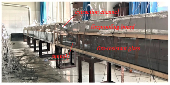
Figure 4.
Model tunnel system.
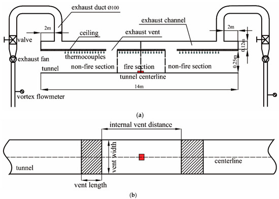
Figure 5.
Schematic layout of model tunnel (a) front view, (b) top view.
The smoke temperature was measured using K-type thermocouples with an accuracy of 2.5 °C and a diameter of 1 mm. As shown in Figure 5a, considering the tunnel center as the origin, the thermocouples were symmetrically installed 1 cm below the ceiling along the longitudinal center line of the tunnel, with an interval of 0.1 m. The Agilent 34980A was used to collect the temperature data every 5 s. The volumetric flow rate was measured using vortex flowmeters with an accuracy of 1.5%.
To simplify descriptions in the later sections of this paper, the fire section and non-fire section of the tunnel were defined as shown in Figure 5a.
2.2. Fire Load
The fire source simulated by a methanol pool fire was located at the center of the model tunnel floor longitudinally and transversely. The HRRs were calculated using the following formula.
where χ is the combustion efficiency, is the mass loss rate, and ΔH is the heat of combustion.
Methanol burns without a visible flame, indicating that very little soot is produced. Therefore, the combustion efficiency χ for the methanol can be considered as 1 [23]. The combustion heat of methanol ΔH is always used as 19.93 kJ/g, and the mass loss rate of the fuel was measured using an electronic balance in the laboratory. Three square pools with a height of 2 cm were used for the experiments. In order to clearly observe the smoke spreading configuration, incense was used as tracer agent and the smoke spreading configuration lit by the laser source was recorded using a digital video in the experiment. The HRRs in model scale and in full scale calculated using Equation (4) and Equation (1) were listed in Table 1.

Table 1.
Heat release rates (HRRs).
2.3. Experimental Conditions
A total of 116 experiments were tested in this study, as shown in Table 2.
Table 2.
Summary of experimental conditions.
3. Experimental Results and Discussion
In this study, the ceiling temperature distribution on both sides of the fire source is symmetrical. Therefore, the ceiling temperature of one half side of the tunnel is investigated. Meanwhile, only the ceiling temperature in the fire section is analyzed because this paper mainly focuses on the case in which the smoke flow is confined to the zone between two extraction vents, namely fire section. Besides, it is actually assumed that the heat transfer mechanisms are predominantly convective when it comes to the one-dimensional stage of smoke flow [24,25].
3.1. Longitudinal Temperature Decay
Based on the one-dimensional theory [24] and the previous studies [26], the longitudinal temperature rise decay can be expressed as Equation (5).
where x is the distance from the fire location, k is the decay coefficient, ΔTx is the ceiling temperature rise, ΔTref is the reference temperature rise, and xref is the distance of reference location from the fire location. According to the reference [27], the location at the distance of 0.4 m from fire source is selected as the reference location xref in this study.
Figure 6 shows the longitudinal temperature decay in the fire section can be expressed as Equation (5). The decay coefficient k is gained by summarizing and fitting experimental data and its value is 0.536. The correlation coefficient is 0.98, representing a good correlation.
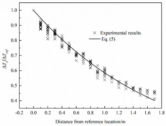
Figure 6.
Longitudinal temperature decay in the fire section.
3.2. Temperature Distribution Below the Ceiling
To analyze and calculate the ceiling temperature distribution, a dimensionless temperature rise is adopted from the reference [28], as shown in Equation (6).
where, Q* = Q/(ρ0 × cp × T0 × g2/1 × H2/5), ΔT is the ceiling smoke temperature rise, ΔT* is the dimensionless ceiling smoke temperature rise.
Figure 7 shows that HRR does not have a significant influence on the dimensionless temperature rise in the fire section. Moreover, the internal distance between two extraction vents, the extraction vent length and the exhaust volumetric flow rate have no effect on the dimensionless temperature rise in the fire section as shown in Figure 8. This is because that the same force acted on both sides of the fire source and the fire did not tilt as the symmetrical property during experiments. The above analysis indicates that the dimensionless temperature rise is independent on HRR, internal distance between two extraction vents, extraction vent length and exhaust volumetric flow rate. Therefore, the dimensionless reference temperature rise can be considered as a constant in this study, which is 3.12 by averaging the results of all tests.
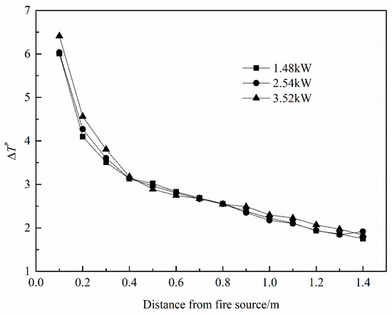
Figure 7.
Effect of heat release rate on the dimensionless smoke temperature rise in the fire section.
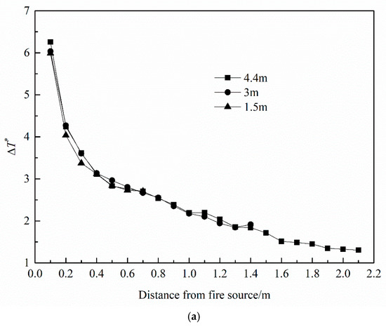
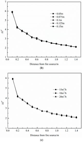
Figure 8.
Effects of (a) distance between two extraction vents, (b) extraction vent length and (c) exhaust volumetric flow rate on the dimensionless smoke temperature rise.
Substituting Equation (6) into Equation (5), the ceiling temperature rise distribution can be expressed as Equation (7).
Substituting the dimensionless reference temperature rise and decay coefficient k into Equation (7), we can get the formula of the ceiling temperature distribution in the fire section in Equation (8).
Experimental results and Equation (8) are plotted as shown in Figure 9. It can be seen that Equation (8) could be used to predict the ceiling temperature distribution in fire section.
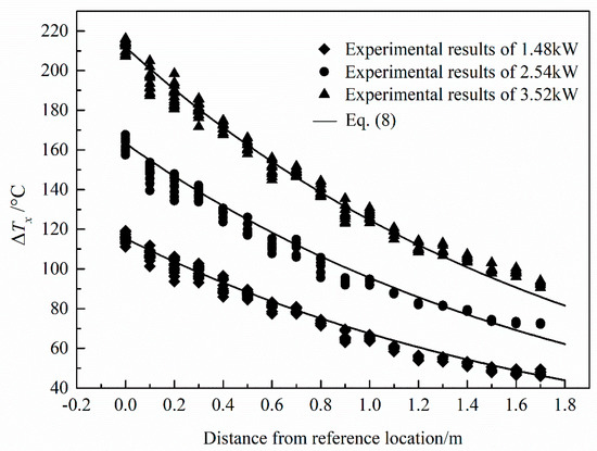
Figure 9.
Comparisons of smoke temperature rise below the ceiling in the fire section between experimental results and results obtained from Equation (8).
3.3. Critical Exhaust Volumetric Flow Rate
Through observing the smoke spreading configurations recorded by the digital video under various exhaust volumetric flow rates during the tests, the critical exhaust volumetric flow rate can be found. For example, Figure 10 shows the recorded smoke configuration for Test No. 6–9 in Table 2, it can be seen that the smoke cannot spread to the downstream of the extraction vent when the exhaust volumetric flow rate is larger than 18 m3/h. Therefore, the critical exhaust volumetric flow rate can be considered as 18 m3/h according to the definition in Section 1. All experimental results of the critical exhaust volumetric flow rate in this paper are shown in Table 3.
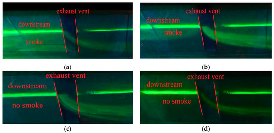
Figure 10.
Smoke configurations with different exhaust volumetric flow rate for Test No. 6–9 in Table 2. (a) 15 m3/h; (b) 17.5 m3/h; (c) 18 m3/h; (d) 18.5 m3/h.
Table 3.
Summary of experimental results on critical exhaust volumetric flow rate.
Table 3 indicates that the critical exhaust volumetric flow rate increases with the HRR. This is because the mass rate of the plume increases with the HRR [29]. While the critical exhaust volume flow rate increases with the decrease of extraction vent length and internal distance between two extraction vents. It is clear that the critical exhaust volume flow rate needs to increase to prevent the smoke from spreading downstream of the extraction vent when the extraction vent length is very small. According to the Section 3.2, the smoke temperature below the extraction vent will increase with the decrease of internal distance between two extraction vents, which means static pressure driving the smoke flow along the ceiling increases [30]. Therefore, the critical exhaust volume flow rate has to rise to resist growing static pressure in order to control the smoke in the zone between the two extraction vents.
4. Theoretical Prediction for the Critical Exhaust Volumetric Flow Rate
In order to predict the critical exhaust volumetric flow rate, an empirical equation is developed combining the one-dimensional theory, experimental phenomenon and the analysis of forces acting at the smoke underneath the extraction vent.
Figure 11 shows the physical model in this study. Because the physical model was symmetrical and the exhaust volumetric flow rate on both sides of fire source was equivalent during the experiments, the smoke propagation is a symmetric flow. Therefore, in order to simplify the analysis, only the right part of the physical model is selected to carry out the theoretical analysis.
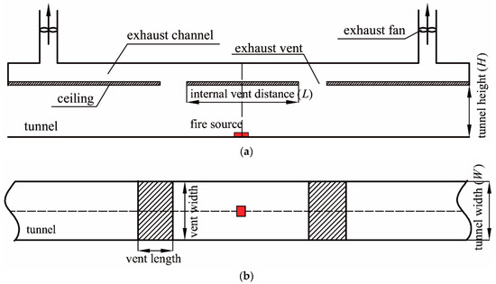
Figure 11.
The schematic layout of physical model (a) front view, (b) top view.
As shown in Figure 12, when the system operates under the critical exhaust volumetric flow rate, the smoke cannot spread downstream of the extraction vent and inclined angle β exists, which is evidenced by the recorded smoke spreading configuration in Figure 10c. This is caused by the vertical inertia force Fi and the horizontal force Fb acting at the smoke beneath the extraction as shown in Figure 13. It can be deduced that the ratio of the vertical inertia force Fi to the horizontal force Fb is associated with tanβ, which can be written as Equation (9)
where tanβ is expressed as
where d and l are smoke layer thickness and extraction vent length, respectively.
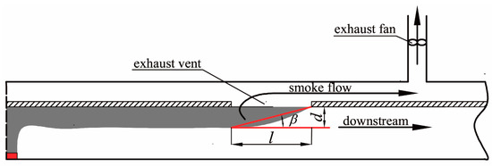
Figure 12.
Schematic diagram of inclined angle β.
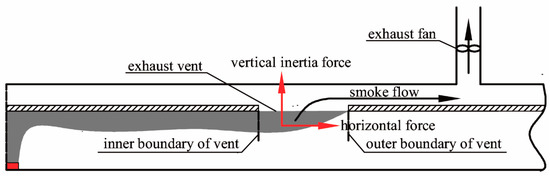
Figure 13.
Forces acting at the smoke beneath the extraction.
So, Equation (9) is rewritten as
The vertical inertia force Fi caused by the process of smoke extraction can be expressed as
Meanwhile, the exhaust velocity can be written as
where, ρe is the density of exhausted smoke, u is the exhaust velocity of vent, l is the extraction vent length, w is the extraction vent width, V is the critical exhaust volumetric flow rate of the extraction vent.
The horizontal force Fb resulted from static pressure can be expressed as [30]
where Δρb is the density difference between the ambient air and the smoke under the inner boundary of the extraction vent, W is the tunnel width.
Combining Equations (12)–(14), the ratio of the vertical inertia force Fi to the horizontal force Fb can be expressed as Equation (15)
Both temperatures of the exhausted smoke and the smoke under the inner boundary of the control volume increase with the HRR, which means the densities of these two types of smoke, ρe and ρb decrease with the increase of HRR. Therefore, the relationship between ρe and ρb can be assumed as
where ζ is a constant.
Substituting Equation (16) into Equation (15)
Experimental results show the critical exhaust volume flow rate increases with the decrease of the extraction vent length, and the recorded smoke spreading configurations illustrate the inclined angle β also increases with the decrease of the extraction vent length as shown in Figure 14. According to the analysis in Section 3.2, the ceiling temperature distribution in the fire section is independent on the extraction vent length, and smoke layer thickness is only related to the tunnel width and height in the one-dimensional stage of smoke flow [27], which means the horizontal force remain unchanged for the same HRR and internal distance between two extraction vents. The vertical inertia force has to increase to prevent the smoke spreading downstream of the extraction vent with the decrease of the vent length, which make the critical exhaust volume flow rate increase. This indicates that the ratio of the inertia force Fi to the buoyancy force Fb will approach infinity as the extraction vent length approaches zero. While, the ratio of the inertia force Fi to the buoyancy force Fb will approach zero as the extraction vent length is long enough as shown in Equation (11). So, based on the above analysis, Equation (11) can be hypothetically written as following.
where a and b are constants.
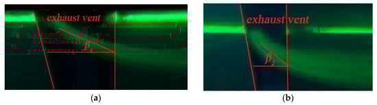
Figure 14.
Inclined angle β under different extraction vent lengths (a) 0.1 m, (b) 0.05 m.
Substituting Equation (17) into Equation (18)
where c = a/ζ.
From the reference [27], the smoke layer thickness can be expressed as Equation (20)
where H is the tunnel height.
According to the ideal gas equation
where, ρb is the smoke density under the inner boundary of the extraction vent, ΔTb is temperature difference between the ambient air and the smoke under the inner boundary of the extraction vent, T0 is the ambient temperature.
When the distance from the fire source to the inner boundary of the extraction vent is substituted to Equation (7), we can get the smoke temperature rise under the inner boundary of the extraction vent ΔTb as follows.
Combining w = W and Equations (20)–(22), Equation (19) can be written as Equation (23)
To determine the value of b and c, experimental results are summarized and fitted using Equation (23) as shown in Figure 15. The value of b and c are 1.34 and 0.25, respectively. The correlation coefficient is 0.991, representing a good correlation.
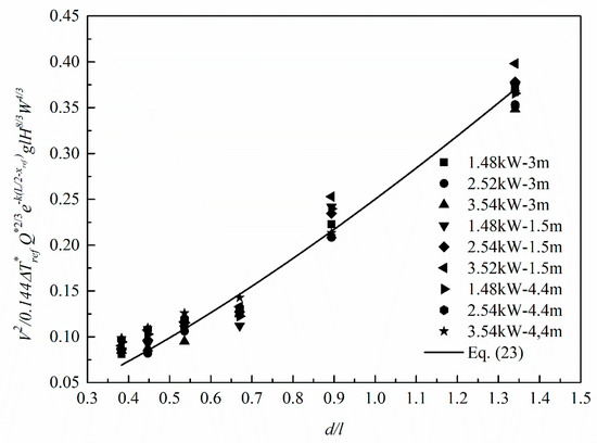
Figure 15.
Experimental results fitted by Equation (23).
Substituting the value of b and c into Equation (23), we can obtain the empirical formula of critical exhaust volumetric flow rate as the following.
Experimental data and results obtained from Equation (24) are plotted in Figure 16. It can be seen that Equation (24) can predict the critical exhaust volumetric flow rate well.
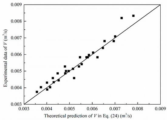
Figure 16.
Comparisons of critical exhaust volumetric flow rate between experimental results and proposed empirical Equation (24).
5. Conclusions
In this paper, the ceiling temperature distribution and critical exhaust volumetric flow rate was investigated in the long-distance subway tunnel fire with a two-point extraction ventilation system.
Based on the Froude modeling, a series of 1/20 reduced-scale experiments were carried out to investigate the ceiling temperature distribution and critical exhaust volumetric flow rate. Factors including the HRR, the internal distance between two extraction vents, the extraction vent length and the exhaust volumetric flow rate were taken into account. Experimental results show that the dimensionless ceiling temperature is independent on HRR, internal distance between two extraction vents, extraction vent length and exhaust volumetric flow rate. Moreover, the critical exhaust volumetric flow rate increases with HRR, but it decreases with the increase of extraction vent length and internal distance between two extraction vents.
Finally, an empirical equation was derived to predict the critical exhaust volumetric flow rate combining the one-dimensional theory, experimental phenomenon and the analysis of forces acting at the smoke underneath the extraction vent. Experimental data were used to determine the coefficients in the empirical equation. Compared with experimental results, the developed empirical equation in this paper can predict the critical exhaust volumetric flow rate well.
Author Contributions
Z.Y. and P.Z. conceived and designed the experiment. P.Z. performed the experiments. P.Z. and Z.Y. analyzed experimental data. Y.Y., N.Y. and T.Y. put forward helpful suggestions about the experimental design and the analysis of experimental results. P.Z., Z.Y. and T.Y. wrote the paper.
Funding
This work was supported by National Science Foundation of China (NSFC) [grant number 51708454]; and the Fundamental Research Funds for the Central Universities [grant number 2682016CX028].
Acknowledgments
The authors would also like to thank Yiteng Fan, Tao Chen and Ao Qin for their assistance in the experiments.
Conflicts of Interest
The authors declare no conflict of interest.
Nomenclature
| d | smoke layer thickness (m) |
| Fi | vertical inertia force (N) |
| Fb | horizontal force (N) |
| g | gravity acceleration (m/s2) |
| H | tunnel height (m) |
| k | decay coefficient (m−1) |
| L | internal distance between two extraction vents (m) |
| l | extraction vent length (m) |
| T0 | ambient temperature (K) |
| Tx | smoke temperature (K) |
| Tref | reference temperature (K) |
| u | exhaust velocity (m/s) |
| V | critical exhaust volumetric flow rate of vent (m3/s) |
| W | tunnel width (m) |
| w | extraction vent width (m) |
| x | distance from fire location (m) |
| xref | reference location (m) |
| Greek symbols | |
| ρ0 | ambient density (kg/m3) |
| ρe | density of exhausted smoke (kg/m3) |
| ρb | density of smoke underneath the extraction vent (kg/m3) |
| Δ | difference property between smoke and ambient |
| β | inclined angle |
| α | ratio of small-scale to full-scale |
| Subscript | |
| f | full-scale property |
| m | reduced-scale property |
References
- Ingason, H.; Li, Y.Z.; Lönnermark, A. Tunnel Fire Dynamics; Springer: Berlin, Germany, 2014. [Google Scholar]
- Beard, A.N. Fire safety in tunnels. Fire Saf. J. 2009, 44, 276–278. [Google Scholar] [CrossRef]
- Drenda, J.; Domagała, L.; Musioł, D.; Pach, G.; Różański, Z. An analysis of selected jet fans used in chambers of KGHM mines with respect to the air stream range. Tunn. Undergr. Space Technol. 2018, 82, 303–314. [Google Scholar] [CrossRef]
- Król, M.; Król, A.; Koper, A.; Wrona, P. The influence of natural draught on the air flow in a tunnel with longitudinal ventilation. Tunn. Undergr. Space Technol. 2019, 85, 140–148. [Google Scholar] [CrossRef]
- Thomas, P. The Movement of Buoyant Fluid against a Stream and the Venting of Underground Fires; Fire Research Station: Boreham Wood, UK, 1958. [Google Scholar]
- Oka, Y.; Atkinson, G.T. Control of smoke flow in tunnel fires. Fire Saf. J. 1995, 25, 305–322. [Google Scholar] [CrossRef]
- Bakar, M.; Wu, Y. Control of smoke flow in tunnel fires using longitudinal ventilation systems—A study of the critical velocity. Fire Saf. J. 2000, 35, 363–390. [Google Scholar]
- Carvel, R.; Beard, A.; Jowitt, P. The influence of longitudinal ventilation systems on fires in tunnels. Tunn. Undergr. Technol. 2001, 16, 3–21. [Google Scholar] [CrossRef]
- Kunsch, J. Simple model for control of fire gases in a ventilated tunnel. Fire Saf. J. 2002, 37, 67–81. [Google Scholar] [CrossRef]
- Li, Y.Z.; Lei, B.; Ingason, H. Study of critical velocity and back layering length in longitudinally ventilated tunnel fires. Fire Saf. J. 2010, 45, 361–370. [Google Scholar] [CrossRef]
- Li, Y.Z.; Lei, B.; Ingason, H. The maximum temperature of buoyancy-driven smoke flow beneath the ceiling in tunnel fires. Fire Saf. J. 2011, 46, 204–210. [Google Scholar] [CrossRef]
- Vauquelin, O.; Mégret, O. Smoke extraction experiments in case of fire in a tunnel. Fire Saf. J. 2002, 37, 525–533. [Google Scholar] [CrossRef]
- Vauquelin, O.; Telle, D. Definition and experimental evaluation of the smoke “confinement velocity” in tunnel fires. Fire Saf. J. 2005, 40, 320–330. [Google Scholar] [CrossRef]
- Lin, C.-J.; Chuah, Y.K. A study on long tunnel smoke extraction strategies by numerical simulation. Tunn. Undergr. Technol. 2008, 23, 522–530. [Google Scholar] [CrossRef]
- Ingason, H.; Li, Y.Z. Model scale tunnel fire tests with point extraction ventilation. J. Fire Prot. Eng. 2011, 21, 5–36. [Google Scholar] [CrossRef]
- Zhu, H.; Shen, Y.; Yan, Z.; Guo, Q.; Guo, Q. A numerical study on the feasibility and efficiency of point smoke extraction strategies in large cross-section shield tunnel fires using CFD modeling. J. Loss Prev. Process. Ind. 2016, 44, 158–170. [Google Scholar] [CrossRef]
- Mei, F.; Tang, F.; Ling, X.; Yu, J. Evolution characteristics of fire smoke layer thickness in a mechanical ventilation tunnel with multiple point extraction. Appl. Therm. Eng. 2017, 111, 248–256. [Google Scholar] [CrossRef]
- Tang, F.; Cao, Z.; Palacios, A.; Wang, Q. A study on the maximum temperature of ceiling jet induced by rectangular-source fires in a tunnel using ceiling smoke extraction. Int. J. Therm. Sci. 2018, 127, 329–334. [Google Scholar] [CrossRef]
- Hu, L.; Chen, L.; Tang, W. A global model on temperature profile of buoyant ceiling gas flow in a channel with combining mass and heat loss due to ceiling extraction and longitudinal forced air flow. Int. J. Heat Mass Transf. 2014, 79, 885–892. [Google Scholar] [CrossRef]
- Chen, L.; Hu, L.; Zhang, X.; Zhang, X.; Zhang, X.; Yang, L. Thermal buoyant smoke back-layering flow length in a longitudinal ventilated tunnel with ceiling extraction at difference distance from heat source. Appl. Therm. Eng. 2015, 78, 129–135. [Google Scholar] [CrossRef]
- Tanaka, F.; Majima, S.; Kato, M.; Kawabata, N. Performance validation of a hybrid ventilation strategy comprising longitudinal and point ventilation by a fire experiment using a model-scale tunnel. Fire Saf. J. 2015, 71, 287–298. [Google Scholar] [CrossRef]
- Quintiere, J.G. Scaling applications in fire research. Fire Saf. J. 1989, 15, 3–29. [Google Scholar] [CrossRef]
- Karlsson, B.; Quintiere, J.G. Enclosure Fire Dynamics; CRC Press: Boca Raton, FL, USA, 2000. [Google Scholar]
- Kunsch, J.P. Critical velocity and range of a fire-gas plume in a ventilated tunnel. Atmos. Environ. 1999, 33, 13–24. [Google Scholar] [CrossRef]
- Ji, J.; Zhong, W.; Li, K.Y.; Shen, X.B.; Zhang, Y.; Huo, R. A simplified calculation method on maximum smoke temperature under the ceiling in subway station fires. Tunn. Undergr. Space Technol. 2011, 26, 490–496. [Google Scholar] [CrossRef]
- Hu, L.H.; Huo, R.; Chow, W.K.; Wang, H.B.; Yang, R.X. Decay of buoyant smoke layer temperature along the longitudinal direction in tunnel fires. J. Appl. Fire Sci. 2004, 13, 53–77. [Google Scholar] [CrossRef]
- Oka, Y.; Oka, H.; Imazeki, O. Ceiling-jet thickness and vertical distribution along flat-ceilinged horizontal tunnel with natural ventilation. Tunn. Undergr. Technol. 2016, 53, 68–77. [Google Scholar] [CrossRef]
- Yuan, Z.Y.; Lei, B.; Kashef, A. Experimental and Theoretical Study for Tunnel Fires with Natural Ventilation. Fire Technol. 2015, 51, 691–706. [Google Scholar] [CrossRef]
- Heskestad, G. “Fire Plumes,” SFPE Handbook of Fire Protection Engineering, 3rd ed.; National Fire Protection Association: Quincy, MA, USA, 2002. [Google Scholar]
- Chow, W.K.; Gao, Y.; Zhao, J.; Dang, J.; Chow, C.L.; Miao, L. Smoke movement in tilted tunnel fires with longitudinal ventilation. Fire Saf. J. 2015, 75, 14–22. [Google Scholar] [CrossRef]
© 2019 by the authors. Licensee MDPI, Basel, Switzerland. This article is an open access article distributed under the terms and conditions of the Creative Commons Attribution (CC BY) license (http://creativecommons.org/licenses/by/4.0/).