Article

Proportional-Type Sensor Fault Diagnosis Algorithm for DC/DC Boost Converters Based on Disturbance Observer

1
Department of Mechanical Engineering, Korea Advanced Institute of Science and Technology, Daejeon 291, Korea
2
Department of Creative Convergence Engineering, Hanbat National University, Daejeon 341-58, Korea
*
Authors to whom correspondence should be addressed.
Energies 2019, 12(8), 1412; https://doi.org/10.3390/en12081412
Submission received: 1 February 2019 / Revised: 3 April 2019 / Accepted: 4 April 2019 / Published: 12 April 2019

Abstract

:
This study seeks an advanced sensor fault diagnosis algorithm for DC/DC boost converters governed by nonlinear dynamics with parameter and load uncertainties. The proposed algorithm is designed with a combination of proportional-type state observer and disturbance observer (DOB) without integral actions. The convergence, performance recovery and offset-free properties of the proposed algorithm are derived by analyzing the estimation error dynamics. An optimization process to assign the optimal feedback gain for the state observer is also provided. Finally, a fault diagnosis criteria is introduced to identify the location and type of sensor faults online using normalized residuals. The experimental results verify the effectiveness of the suggested technique under variable operating conditions and three types of sensor faults using a prototype 3 kW DC/DC boost converter.

1. Introduction

DC/DC boost converters play important roles in various industrial applications such as solar/wind power systems, electric vehicles and various home appliances [1,2,3,4,5,6,7], where the input DC power needs to be converted to a desired high-quality output DC power in the presence of several practical uncertainties caused by parameter and load variations.
To control the output voltage of DC/DC boost converters, several control schemes have been proposed, including conventional proportional-integral (PI) controllers [8,9,10] using the cascade control strategy, having an inner-loop current controller and an outer-loop voltage controller, and advanced techniques such as adaptive [11], robust [12] and model predictive [13] controllers. These control schemes are based on feedback from the inductor current and output voltage sensors. However, unexpected faults can occur in the sensors due to equipment aging or environmental interference, including electromagnetic noise, vibration, shock and abrupt temperature changes, which affect the normal operation of the control system. Even if open-loop controls without sensors can be implemented, degradation in the dynamic performance and robustness from parameter uncertainties and load variations cannot be avoided. Accordingly, sensor fault diagnosis and fault-tolerant control algorithms are of paramount importance in the industrial application of DC/DC boost converters.
Fault diagnosis techniques are generally divided into signal-based and model-based approaches [14]. Signal-based methods [15,16] utilize the features of measured signals in which the fault information is reflected. A diagnostic decision on the features is made based on the symptom analysis. Signal-based fault detection methods are widely used for real-time monitoring of electrical or mechanical components in a system, but they are rarely used for sensor fault diagnosis. By contrast, model-based methods, widely adopted for sensor fault diagnosis of power converters, monitor the consistency between the measured sensor outputs of a system and the model-predicted outputs. The model-predicted outputs are generally obtained from state observers such as the adaptive observer [17,18], Luenberger observer [19,20] and extended Kalman filter [21,22].
One of the main considerations in the design of the state observer for sensor fault diagnosis of power converters is that the state observer needs to be insensitive to parameter and load variations to avoid misdiagnosis in normal operations [23]. In this respect, the sliding mode observer [24,25,26] and proportional-integral observer [27,28,29], offering the desirable feature of robustness to bounded uncertainties, showed good performances in fault diagnosis of modular multilevel converters and pulse-width modulation (PWM) rectifiers that contain parameter uncertainties and load variations. Among the few studies on fault diagnosis for DC/DC boost converters [19,20], however, the robustness of the fault diagnosis algorithm was not considered by assuming that the parameters were exactly known or the operating conditions were fixed.
On the other hand, fault isolation, which determines the location of faulty sensors, and fault identification, which determines the type of sensor faults, are also important issues [14]. It was shown that fault isolation can be realized by using a well-designed state observer, even for the case where the three types of faults (i.e., open-circuit fault, gain deviation and abnormal noise) occurred in the current and voltage sensors of the DC/DC boost converter [20] and PWM rectifier [25]. However, to the best of my knowledge, criteria for fault identification for the three types of sensor faults have not been presented yet.
This study proposes a proportional-type state-observer-based sensor fault diagnosis algorithm for DC/DC boost converters, considering the system nonlinear behavior, parameter and load variations. The proposed algorithm comprises two parts: One full-state observer and one disturbance observer (DOB) for removing state estimation offset errors even in the presence of uncertainties from the parameter and load variations. There are three main contributions in this paper. The first is to present an optimization process determining the optimal full-state observer gain under the bilinear matrix inequality (BMI) constraints. The second is to ensure the estimation offset-free and performance recovery properties through analysis of the estimation error dynamics. The third is to devise fault diagnosis criteria to identify the location and type of sensor faults online using normalized residuals. The validity of the proposed algorithm is confirmed with experimental data using a prototype 3 kW DC/DC boost converter.

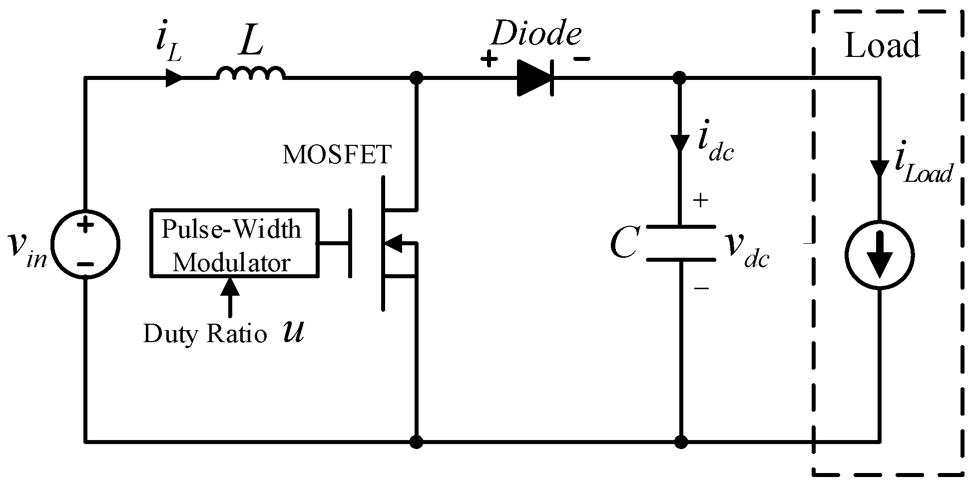
2. DC/DC Boost Converter Nonlinear Dynamics

By applying the averaging technique to the DC/DC boost converter depicted in Figure 1, nonlinear differential equations are obtained as [30]
L i ˙ L ( t ) = ( 1 u ( t ) ) v d c ( t ) + v i n ( t ) ,
C v ˙ d c ( t ) = ( 1 u ( t ) ) i L ( t ) i L o a d ( t ) , t 0 ,
where the averaged inductor current of i L ( t ) and output voltage of v d c ( t ) are treated as the state variables, which are available for feedback. The duty ratio constrained in the interval of [ 0 , 1 ] is denoted as u ( t ) , i.e., u ( t ) [ 0 , 1 ] , which acts as the control action to be used as a degree of freedom. The capacitance and inductance values are denoted as C and L, respectively, and can be significantly changed according to the operating conditions. It is assumed that only the initial value of v i n ( t ) is known ( v i n , 0 ). The load current of i L o a d ( t ) can be also abruptly varied by the passive and active loading conditions, also assumed to be unknown.
Considering the full-state estimator for this application ensuring the offset-free property, the state estimation error is maintained at zero in the steady state. The fault occurrence in the current or voltage sensor would result in a certain level of magnification of the state estimation error. Thus, a proper offset-free full-state estimation algorithm can be used as a fault detector. This study describes a simple full-state observer-based fault diagnosis algorithm, guaranteeing the performance recovery and offset-free properties, without any use of estimation error integral actions.

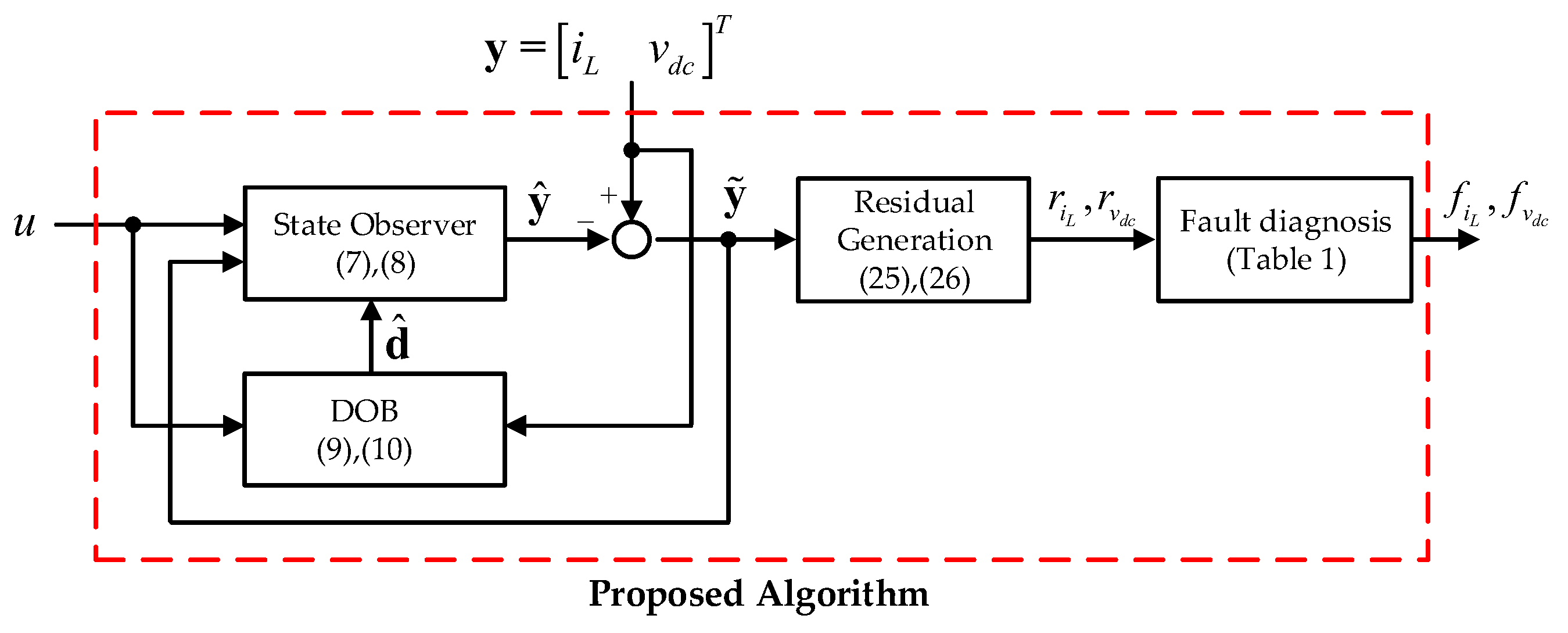
3. Fault Diagnosis Algorithm

3.1. Full-State Observer Design

To consider the practical constraints on the converter parameter and load, the original converter dynamics of (1) and (2) are rewritten as
i ˙ L ( t ) = 1 L 0 ( 1 u ( t ) ) v d c ( t ) + 1 L 0 v i n , 0 + d L ( t ) ,
v ˙ d c ( t ) = 1 C 0 ( 1 u ( t ) ) i L ( t ) + d v ( t ) , t 0 ,
with the nominal parameter values of L 0 and C 0 , where d L ( t ) and d v ( t ) denote the lumped disturbances from the parametric and load uncertainties. The state vector of x ( t ) : = i L ( t ) v d c ( t ) T leads to the linear time-varying system for the dynamical Equations of (3) and (4) as
x ˙ ( t ) = A ( u ( t ) ) x ( t ) + c + d ( t ) ,
y ( t ) = x ( t ) , t 0 ,
with the time-varying system matrix of A ( u ( t ) ) : = 0 1 L 0 ( 1 u ( t ) ) 1 C 0 ( 1 u ( t ) ) 0 , known constant vector of c : = 1 L 0 v i n , 0 0 T , and unknown time-varying vector of d ( t ) : = d L ( t ) d v ( t ) T to be estimated by a DOB.
The proposed full-state observer for dynamics of (5) and (6) is given by
x ^ ˙ ( t ) = A ( u ( t ) ) x ^ ( t ) + c + d ^ ( t ) + L ( y ( t ) y ^ ( t ) ) ,
y ^ ( t ) = x ^ ( t ) , t 0 ,
with the estimation gain matrix of L R 2 × 2 and the estimated disturbance of d ^ ( t ) coming from the DOB:
d ^ ( t ) = z ( t ) + l x ( t ) ,
z ˙ ( t ) = l z ( t ) l 2 x ( t ) l ( A ( u ( t ) ) x ( t ) + c ) , l > 0 , t 0 .
Remark 1.
Consider the following optimization problem:
max α > 0 , Q = Q T > 0 , Y α
subject to bilinear matrix inequality (BMI) constraints:
Q A T ( u i ) Y T + A ( u i ) Q Y + 2 α Q 0 , i = 1 , 2 ,
where u 1 : = min t 0 { u ( t ) } = 0 and u 2 : = max t 0 { u ( t ) } = 1 , which yields that
A ( u 1 ) = A ( u ( t ) ) | u ( t ) = u 1 = 0 1 L 0 1 C 0 0 a n d A ( u 2 ) = A ( u ( t ) ) | u ( t ) = u 2 = 0 0 0 0 .
The BMI constraints of (12) correspond to the linear matrix inequality (LMI) constraints for any fixed α > 0 . Therefore, the optimizer of ( Q * , Y * , α * ) to the optimization problem of (11) can be achieved by using the semidefinite programming solver iteratively, and it constitutes the optimal state estimation gain of L * = Y * ( Q * ) 1 . The implication of the optimal solution of L * can be seen by analyzing the state estimation error dynamics. For details, see Section 3.2.
Remark 2.
A necessity for ensuring the existence of a solution to the matrix inequality of (12) corresponds to the observability of the pair ( I 2 × 2 , A ( u i ) ) , i = 1 , 2 . The observability can be investigated by simply checking the full rankness of the observability matrix defined as O i : = I 2 × 2 A ( u i ) R 4 × 2 . It is easily seen that rank ( O i ) = 2 , i = 1 , 2 . Thus, the observability of the pair ( I 2 × 2 , A ( u i ) ) , i = 1 , 2 , is always ensured.

3.2. Closed-Loop Properties

The state estimation error of x ˜ ( t ) : = x ( t ) x ^ ( t ) satisfies the dynamics given as
x ˜ ˙ ( t ) = x ˙ ( t ) x ^ ˙ ( t ) = A L ( u ( t ) ) x ˜ ( t ) + d ˜ ( t ) , t 0 ,
which is obtained using the dynamics of (5) and (7), where A L ( u ( t ) ) : = A ( u ( t ) ) L and d ˜ ( t ) : = d ( t ) d ^ ( t ) , t 0 . It is not trivial to analyze the closed-loop stability of the time-varying nonhomogeneous system of (13) that acts as the basis of following lemmas and theorems. First, Theorem 1 presents the state estimation error convergence property.
Theorem 1.
Suppose that there exists Q = Q T > 0 satisfying the BMI constraints of (12) for some α > 0 and Y R 2 × 2 . Then, the state estimation gain of L = Y P with P : = Q 1 ( > 0 ) guarantees the exponential convergence property, i.e.,
lim t x ^ ( t ) = x ( t ) ,
as d ˙ ( t ) 0 exponentially.
Proof. 
First, for obtaining the dynamics of the DOB output of (9), substitute the DOB output of (9) to the DOB dynamics of (10) as
d ^ ˙ l x ˙ = l ( d ^ l x ) l 2 x l ( A ( u ) x + c ) , t 0 ,
which shows that the estimated disturbance of d ^ is governed by the simple first-order dynamics:
d ^ ˙ = l ( x ˙ A ( u ) x c d ^ ) = l ( d d ^ ) , l > 0 , t 0 ,
where the relationship of (5) is applied. Second, rewrite the BMI of (12) using the state estimation gain of L = Y P as
[ A L T ( u ( t ) ) P + P A L ( u ( t ) ) ] u ( t ) = u i 2 α P , i = 1 , 2 ,
which results in
A L T ( u ) P + P A L ( u ) 2 α P , u [ 0 , 1 ] , t 0 ,
thanks to the result of [31]. Now, consider the positive definite function defined as
V : = 1 2 x ˜ T P x ˜ + γ 2 d ˜ 2 , γ > 0 , t 0 ,
with d ˜ : = d d ^ , whose time-derivative can be obtained along the closed-loop trajectories of (13) and (14) with the resultant matrix inequality of (15) as
V ˙ = x ˜ T P x ˜ ˙ + γ d ˜ T d ˜ ˙ = x ˜ T P ( A L ( u ) x ˜ + d ˜ ) + γ d ˜ T ( l d ˜ + d ˙ ) = 1 2 x ˜ T ( A L T ( u ) P + P A L ( u ) ) x ˜ + x ˜ T P d ˜ γ l d ˜ 2 + γ d ˙ T d ˜ α x ˜ T P x ˜ + α 2 x ˜ T P x ˜ + 1 2 α d ˜ T P d ˜ γ l d ˜ 2 + γ d ˙ T d ˜ α 2 x ˜ T P x ˜ ( γ l λ m a x ( P ) 2 α ) d ˜ 2 + γ d ˙ T d ˜ , t 0 ,
where Young’s inequality [32] verifies the first inequality:
x ˜ T P d ˜ = x ˜ T P P d ˜ ϵ 2 x ˜ T P 2 + 1 2 ϵ P d ˜ 2 , ϵ > 0 , P = P P ,
and the second inequality comes from the spectral inequality [33]:
λ m i n ( P ) d ˜ 2 d ˜ T P d ˜ λ m a x ( P ) d ˜ 2 ,
with λ m i n ( P ) and λ m a x ( P ) being the minimum and maximum eigenvalues of positive-definite matrix of P . The constant of γ : = 1 l ( λ m a x ( P ) 2 α + 1 2 ) achieves an upper bound of V ˙ as
V ˙ α 2 x ˜ T P x ˜ 1 2 d ˜ 2 + γ d ˙ T d ˜ β V + γ d ˙ T d ˜ , t 0 ,
with β : = min { α , 1 γ } . The resulting inequality of (17) implies the strict passivity for the input-output mapping of 0 γ d ˙ x ˜ d ˜ , which implies the L 2 -stability for the same input-output mapping [34]. Therefore, x ^ x as d ˙ 0 , exponentially. □
Theorem 2 derives the state estimation performance recovery property using the result of Theorem 1.
Theorem 2.
Suppose that the assumptions of Theorem 1 hold true and consider the desired state estimation error trajectory of x ˜ * coming from:
x ˜ ˙ * ( t ) = A L ( u ( t ) ) x ˜ * ( t ) , t 0 ,
with a feasible state estimation gain of L satisfying BMI constraints of (12). Then, it holds that
lim t x ˜ ( t ) = x ˜ * ( t )
as d ˙ ( t ) 0 , exponentially.
Proof. 
It follows from the definition of e : = x ˜ * x ˜ that
e ˙ = x ˜ ˙ * x ˜ ˙ = A L ( u ) e d ˜ , t 0 .
Consider the composite-type positive-definite function defined as
V * : = 1 2 e T P e + κ V , κ > 0 , t 0 ,
with the positive-definite function of V defined in (16), which yields its time-derivative using the dynamics of (20) and the inequality of (17) as
V ˙ * = e T P e ˙ + κ V ˙ 1 2 e T ( A L T ( u ) P + P A L ( u ) ) e e T P d ˜ κ β V + κ γ d ˙ T d ˜ β e T P e + β 2 e T P e + 1 2 β d ˜ T P d ˜ κ β V + κ γ d ˙ T d ˜ β 2 e T P e ( κ β λ m a x ( P ) β γ ) V + κ γ d ˙ T d ˜ , t 0 ,
with the applications of Young’s and spectral inequalities to the second and third inequalities, respectively. The constant of κ : = 1 β ( λ m a x ( P ) β γ + 1 ) gives an upper bound of V ˙ as
V ˙ * β 2 e T P e V + κ γ d ˙ T d ˜ ζ V * + κ γ d ˙ T d ˜ , t 0 ,
with ζ : = min { β , 1 κ } . Therefore, x ˜ x ˜ * as d ˙ 0 by the same reasoning of the proof of Theorem 1, which completes the proof. □
The proposed algorithm does not involve any integral action of the state estimation error. Therefore, it is necessary to clarify whether the offset-errors are rejected by the proposed algorithm in actual implementations, as described in Theorem 3.
Theorem 3.
Suppose that the assumptions of Theorem 1 hold true and that a feasible state estimation gain of L makes the matrix of A L ( u ( t ) ) invertible. Then, the proposed algorithm ensures the offset-free property, i.e.,
x ^ ( ) = x ( ) ,
where lim t f ( t ) = f ( ) .
Proof. 
Consider the whole error dynamics of (13) and (14) as
x ˜ ˙ = A L ( u ) x ˜ + d ˜ , d ˜ ˙ = l d ˜ + d ˙ , t 0 ,
which satisfies the equations in the steady state given by:
0 = A L ( u ( ) ) x ˜ ( ) + d ˜ ( ) ,
0 = l d ˜ ( ) .
It can be easily verified that the substitution of (24) to (23) leads to x ˜ ( ) = 0 due to the invertability of matrix A L ( u ) , which completes the proof.  □
Remark 3.
Theorem 3 requires the invertibility of the matrix of A L ( u ( t ) ) . This condition actually holds true for sufficiently small off-diagonal values of L = L 11 L 12 L 21 L 22 . To see this, consider:
d e t ( A L ( u ( t ) ) ) = d e t ( L 11 ( 1 L 0 ( 1 u ( t ) ) + L 12 ) 1 C 0 ( 1 u ( t ) ) + L 21 L 22 ) = L 11 L 22 + ( 1 L 0 ( 1 u ( t ) ) + L 12 ) ( 1 C 0 ( 1 u ( t ) ) + L 21 ) L 11 L 22 + 1 L 0 C 0 ( 1 u ( t ) ) 2 0 , t 0 ,
for sufficiently small values of L 12 and L 21 .

3.3. Normalized Residual and Fault Diagnosis Criteria

The main fault types of sensors include open-circuit fault, gain deviation, and abnormal noise [25]. An open-circuit fault occurs when the sensors are disconnected or damaged, leading to measured values remaining at zero. Gain deviation leads the measured values to be k ( k > 0 ) times of real values when the internal signal amplifiers of the sensors break down. Abnormal noise may be introduced into the measured values by external disturbance, even covering the real values.
The differences between the measured and observed values are compared with thresholds in real time to detect and identify the types of the fault. Since the inductor current and output voltage vary with operating conditions, the state estimation errors normalized to the state references are selected as normalized residuals that are determined by
r i L ( t ) = i L ( t ) i ^ L ( t ) i L * ( t ) ,
r v d c ( t ) = v d c ( t ) v ^ d c ( t ) v d c * ( t ) ,
where i L * and v d c * are the state references of the inductor current and output voltage. Using the normalized residuals, the three types of sensor faults can be diagnosed on the same criteria with the threshold r t h for various operating conditions as Table 1. From the criteria, it is assumed that one of the three types of sensor faults has occurred when the measured and observed values differ by more than 100 r t h % of the state reference. At the moment when a sensor fault is detected, the control system reconfiguration is realized by substituting the observed values for the faulty sensor information until the fault recovers.
Figure 2 depicts the proposed sensor fault diagnosis system.

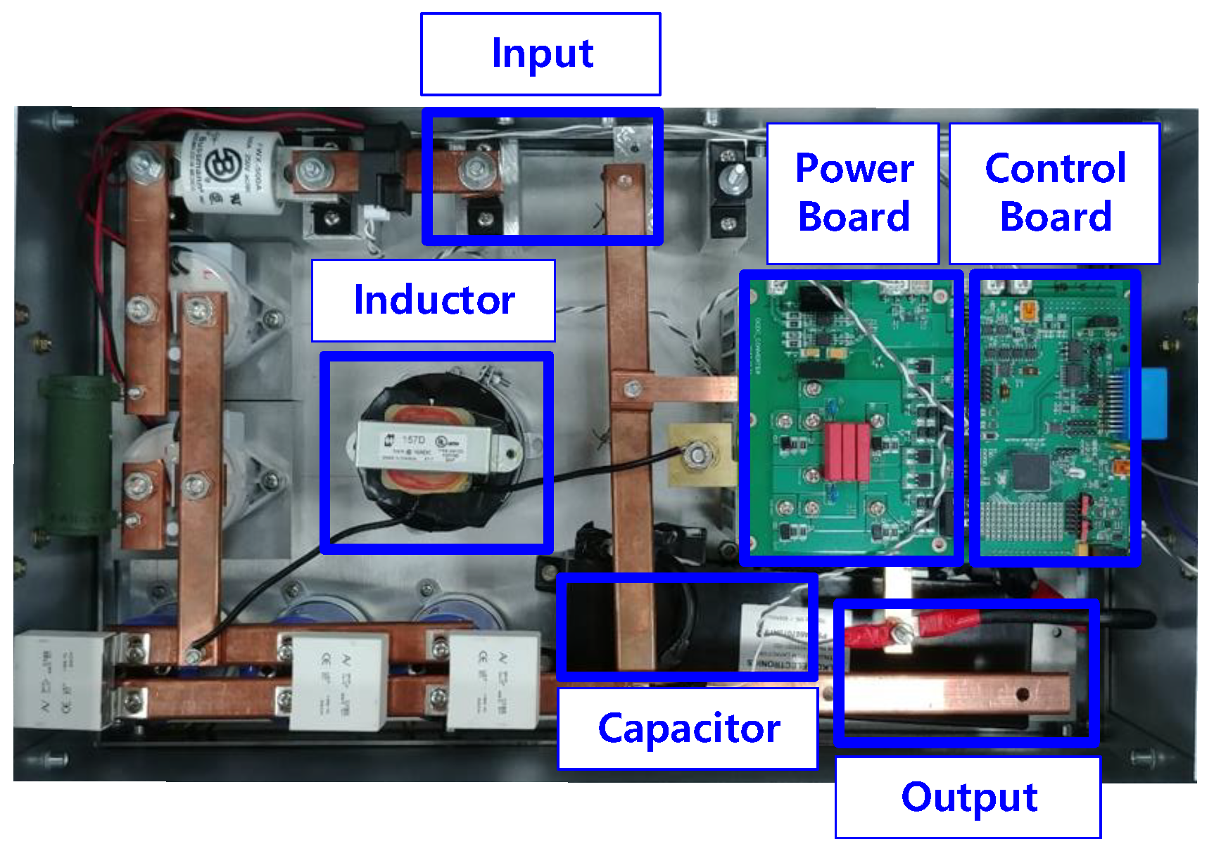
4. Experimental Results

Experimental verification was conducted to evaluate the efficacy of the proposed fault diagnosis algorithm in comparison with the proportional-integral (PI) observer, using a 3 kW prototype DC/DC boost converter, where a MOSFET (IXFN210N30P3, IXYS) was used, the inductor and capacitor values were given by L = 500 μ H, C = 700 μ F, and it was assumed for their nominal values to be L 0 = 0.7 L mH, C 0 = 1.2 C μ F to consider parameter variation. The input DC source voltage was initially set to v i n , 0 = 50 V. A Texas Instruments (TI) DSP28377 was used to implement the fault diagnosis and an output voltage tracking control algorithm. The period of the fault diagnosis algorithm was set to be 1 ms, and the periods of the voltage tracking control and switching operations were chosen to be synchronized as 0.1 ms. The experimental data (e.g., the output voltage, normalized residuals and fault flags) were collected using a Raspberry Pi3 Model B with 1 kHz sampling rate. Figure 3 shows the experimental setup.
The PI observer employed with the nominal parameters for the comparison is given by
x ^ ˙ ( t ) = A ( u ( t ) ) x ( t ) + c + L 1 ( y ( t ) y ^ ( t ) ) + σ ( t ) ,
σ ˙ ( t ) = L 2 ( y ( t ) y ^ ( t ) ) ,
y ^ ( t ) = x ^ ( t ) , t 0 ,
with the estimation gain matrices of L 1 , L 2 R 2 × 2 , which were tuned as
L 1 = 600 0 0 1100 , L 2 = 50000 0 0 100000
to locate the closed-loop eigenvalues of the observer at −100, −100, −500 and −1000. The estimation gain matrix of the proposed observer was obtained by solving the optimization problem (11) as
L = 100.7697 0.0029 0.0068 100.3207
and it gives the closed-loop eigenvalues of the matrix A L ( u ) as 100 ± 922 i for u = u 1 + u 2 2 . (The dominant closed-loop eigenvalues of both observers were set to −100 equally for fairness of the comparison.) The design parameter for the DOBs was selected as l = 1750 .
The threshold r t h was selected as 0.2, which was a value larger than the maximum of the normalized residuals for all operating conditions under normal operations of the sensors with a sufficient margin.

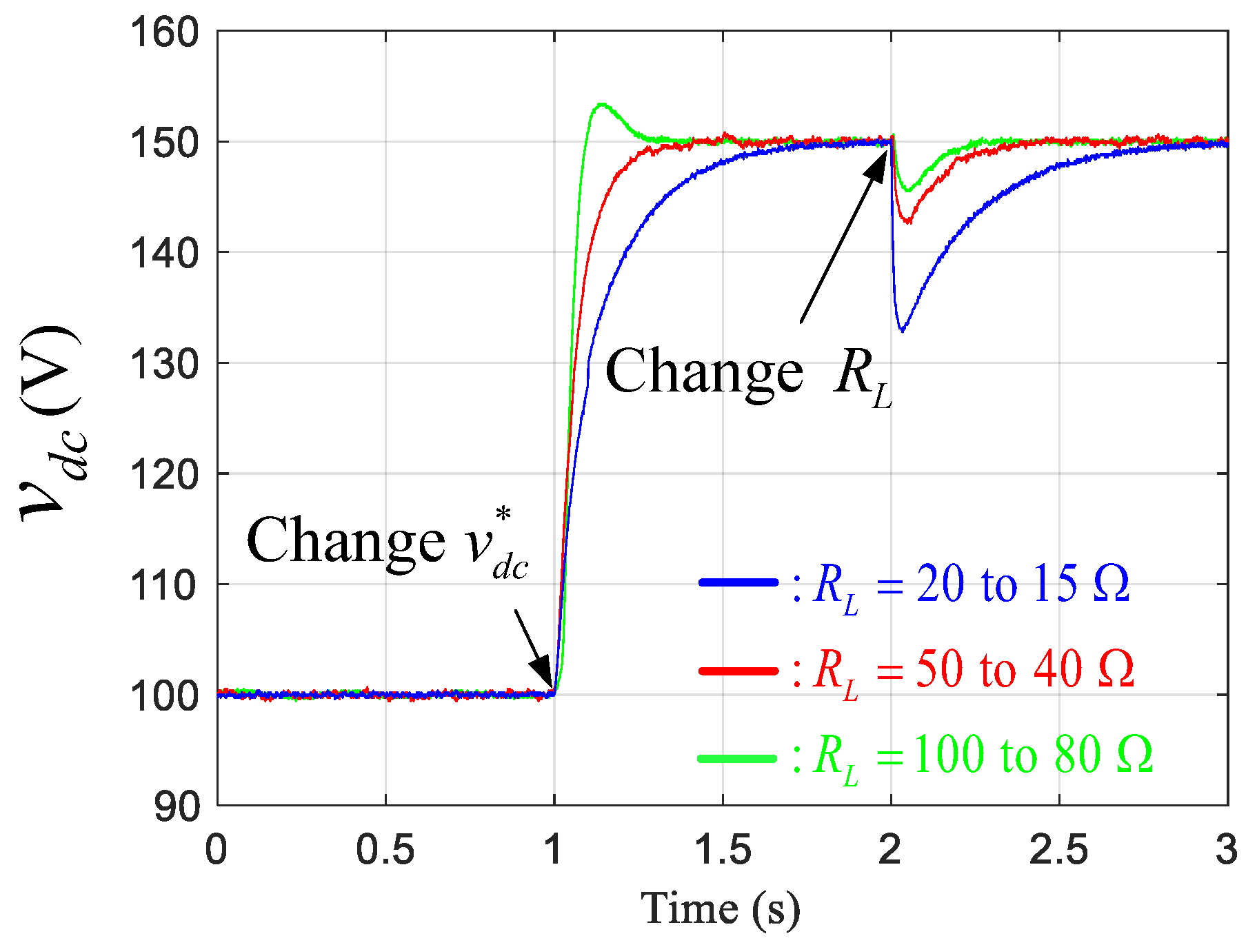
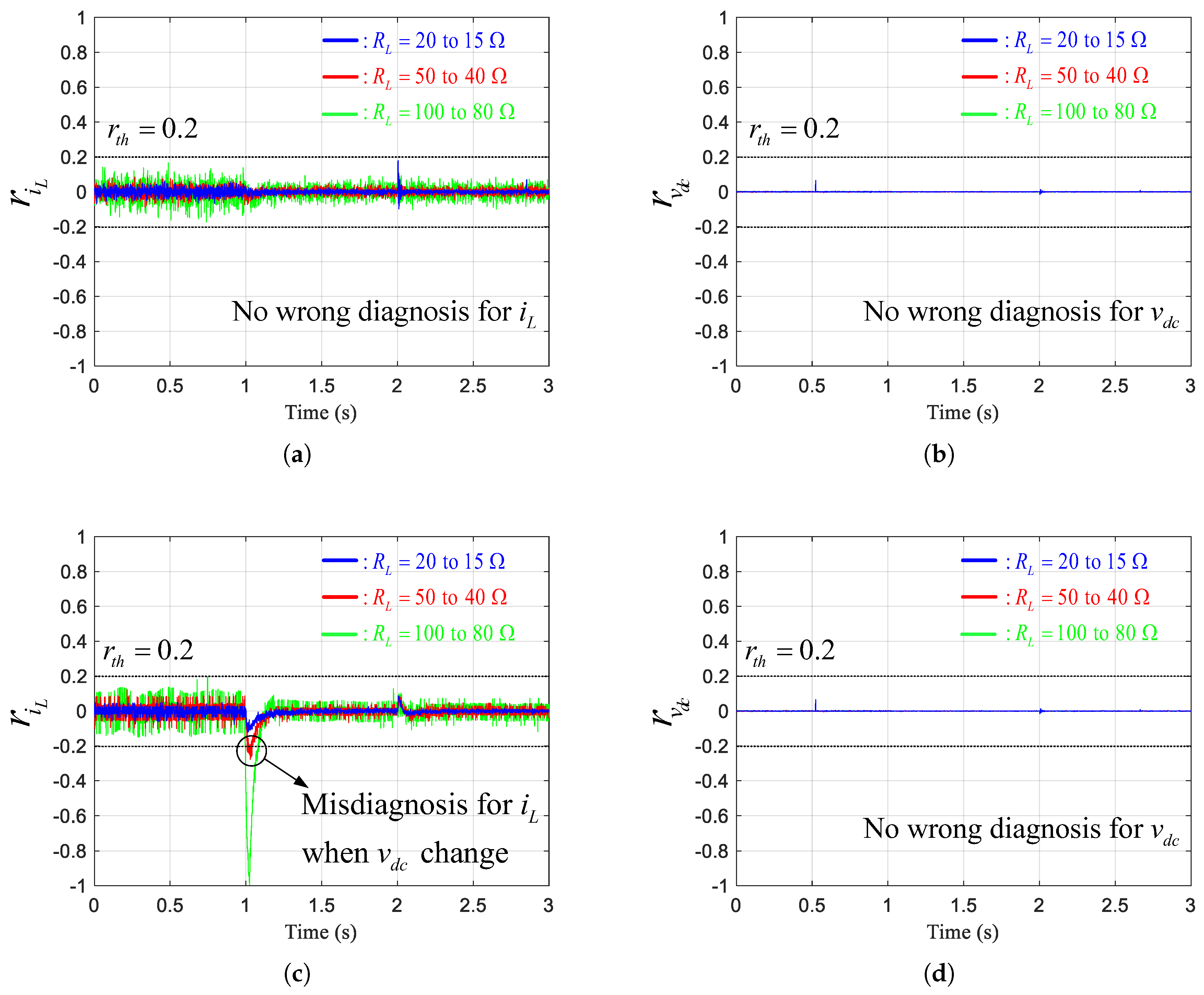
4.1. Experiments under Healthy Conditions

The output voltage of v d c was shifted from 100 to 150 V at t = 1 s, and three load change conditions were given at t = 2 s, where the resistive load of R L was shifted from 20 to 15 Ω , 50 to 40 Ω , and 100 to 80 Ω as depicted in Figure 4. The inductor current and output voltage sensors operated under healthy conditions. The normalized residuals of the inductor current and output voltage are shown in Figure 5.
From the convergence of the residuals to zero at steady state, it can be seen that both observers have an offset-free property for the state estimation despite parameter and load uncertainties. When the operating conditions changed, however, the inductor current residuals of the PI observer exceeded the threshold to a different degree for different resistive load conditions, leading to misdiagnosis for the inductor current sensor. On the other hand, the inductor current residuals of the proposed observer varied slightly to a similar degree for different resistive load conditions remaining under the threshold, which will not lead to misdiagnosis. These results imply that the proposed observer is robust to changes in operating conditions with performance-recovery properties, having the ability to be sensitive only to sensor faults. The PI observer may work better with other estimation gain matrices. The point is, however, that the optimization process presented in Remark 1 to find the optimal gain for the proposed observer greatly reduces the trial-and-error process for gain tuning that is required for the PI observer.
The output voltage residuals of both observers remained sufficiently below the threshold.

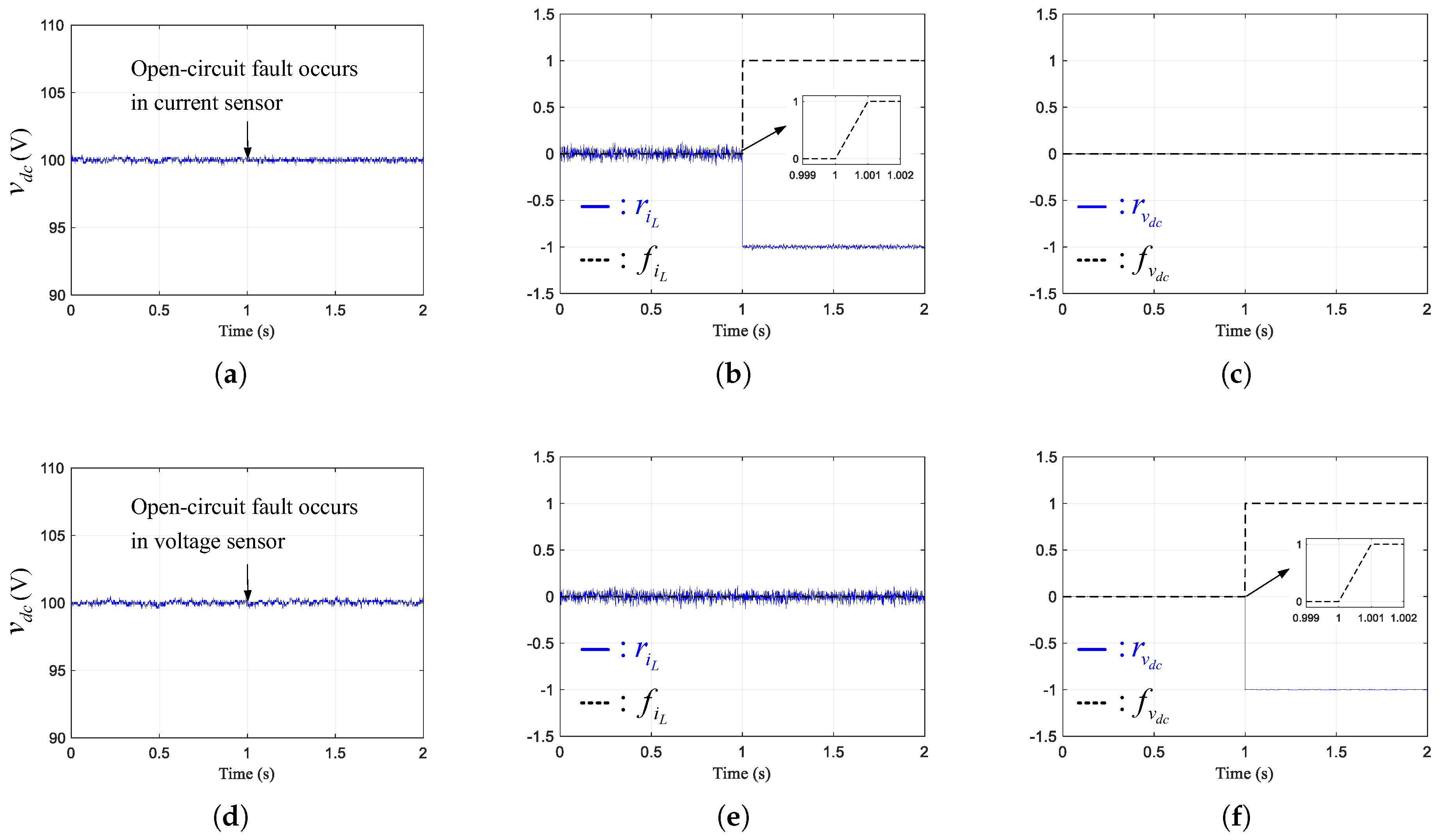
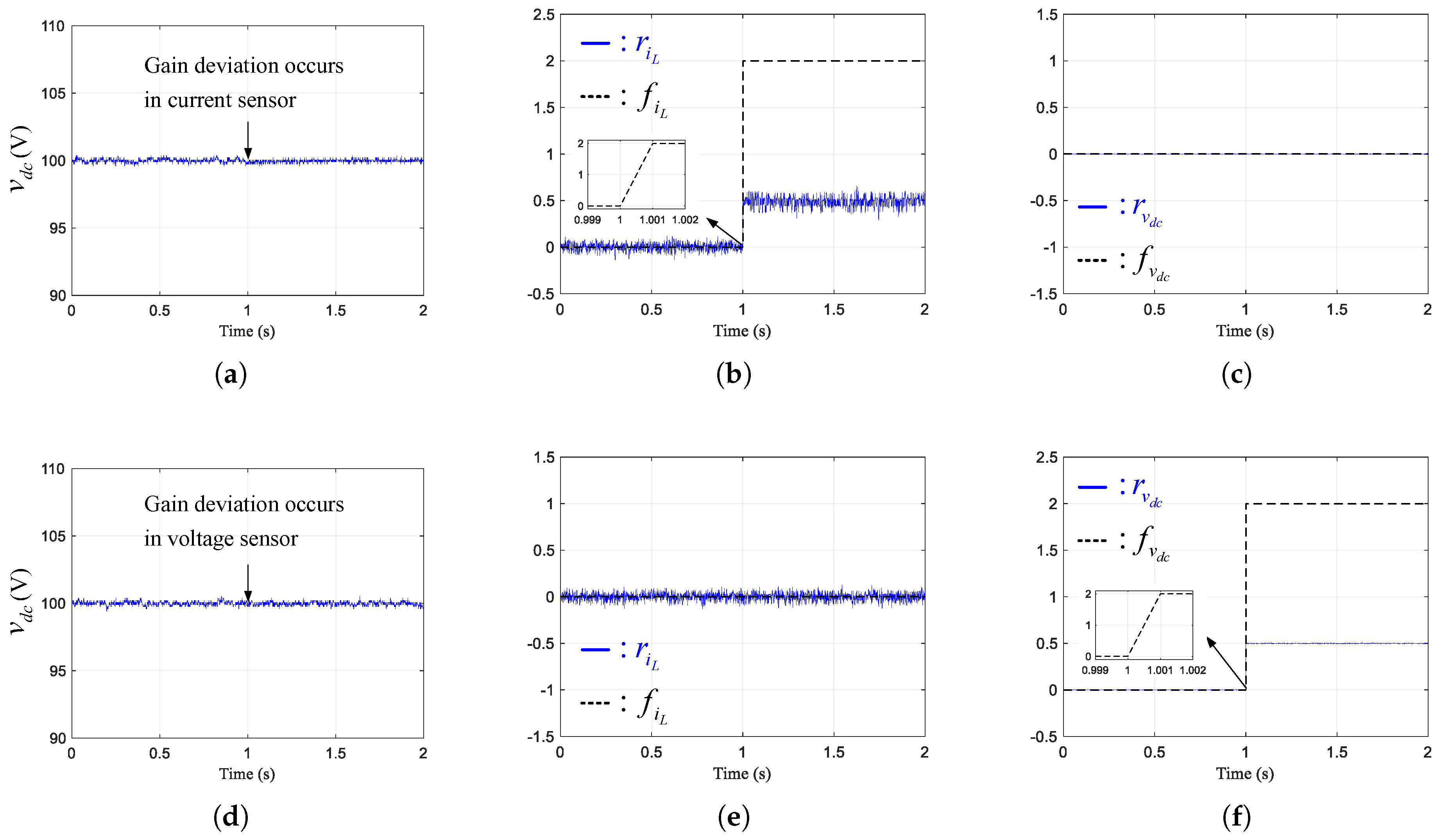
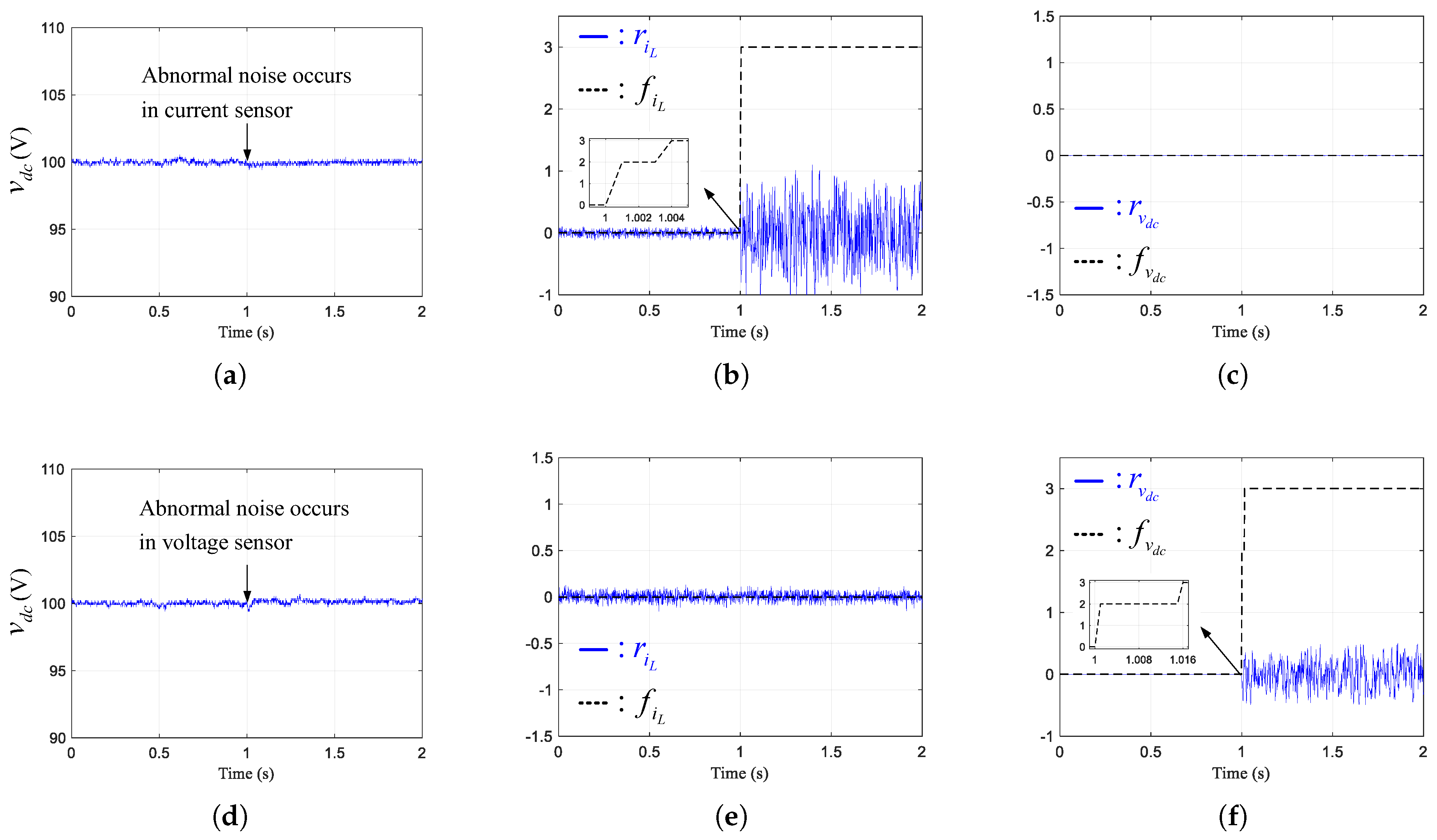
4.2. Experiments under Fault Conditions

Open-circuit fault (0 times of gain), gain deviation (1.5 times of gain) and abnormal noise (white noise within ±5 A or ±50 V) were deliberately applied to the inductor current and output voltage sensors at t = 1 s. The operating condition was fixed at v d c = 100 V and R L = 50 Ω , and only the proposed observer was used for fault diagnosis. The experimental results for the three types of sensor faults (open-circuit fault, gain deviation and abnormal noise) are shown in Figure 6, Figure 7 and Figure 8, respectively.
From Figure 6, the normalized residual of the inductor current (Figure 6b) and output voltage (Figure 6f) decreased from 0 to −1 when the open-circuit faults occur in the current and voltage sensors, respectively, at 1 s. The algorithm immediately diagnosed the issue as open-circuit faults ( f x = 1 ) at the next algorithm step ( t = 1.001 s) and reconfigured the control system, stabilizing the output voltage. The residual of the output voltage (Figure 6c) and inductor current (Figure 6e) did not change for the faults in the current and voltage sensors, respectively.
From Figure 7 and Figure 8, the experimental results of gain deviation and abnormal noise are similar to the open-circuit fault case of Figure 6. When sensor faults occurred, the algorithms immediately diagnosed the fault as gain deviation ( f x = 2 ) or abnormal noise ( f x = 3 ) within 1 ms and 16 ms, respectively, and reconfigured the control system, stabilizing the output voltage.
Thus, the experimental results verified the effectiveness of the proposed fault diagnosis algorithm in the DC/DC booster converter. Since the proposed algorithm is based on the general state equations of (5) and (6), it can be extended to other applications such as buck and buck-boost converters that can be modeled by the same general state equations with difference system matrices [35]. (The only application-specific condition mentioned in Remark 3 also holds true for buck and buck-boost converters.)

5. Conclusions

This study proposes a proportional-type state estimation algorithm with DOBs for a sensor fault diagnosis of DC/DC converter applications. The proposed algorithm was devised under consideration of nonlinear converter behavior and model-plant mismatches, which ensures beneficial closed-loop properties, performance recovery and offset-free properties. An optimization problem was also presented to find an optimal state estimation gain. Moreover, fault diagnosis criteria were proposed to identify the location and type of sensor faults online using normalized residuals. In the experimental study, an acceptable fault diagnosis performance was confirmed using a 3 kW prototype DC/DC boost converter.

Author Contributions

Conceptualization, S.-K.K.; methodology, K.C. and S.-K.K.; investigation, K.C.; writing—original draft preparation, K.C. and S.-K.K.; writing—review and editing, K.-S.K.; supervision, K.-S.K.

Funding

This research was supported by a grant (17TLRP-C135446-01, Development of Hybrid Electric Vehicle Conversion Kit for Diesel Delivery Trucks and its Commercialization for Parcel Services) from the Transportation & Logistics Research Program (TLRP) funded by Ministry of Land, Infrastructure and Transport of Korean Government and partially supported by BK21 Plus Program.

Conflicts of Interest

The authors declare no conflict of interest. The funders had no role in the design of the study; in the collection, analyses, or interpretation of data; in the writing of the manuscript, or in the decision to publish the results.

References

  1. Zhai, L.; Zhang, T.; Cao, Y.; Yang, S.; Kavuma, S.; Feng, H. Conducted EMI prediction and mitigation strategy based on transfer function for a high-low voltage DC-DC converter in electric vehicle. Energies 2018, 11, 1028. [Google Scholar] [CrossRef]
  2. Tran, V.T.; Nguyen, M.K.; Choi, Y.O.; Cho, G.B. Switched-capacitor-based high boost DC-DC converter. Energies 2018, 11, 987. [Google Scholar] [CrossRef]
  3. Padmanaban, S.; Bhaskar, M.S.; Maroti, P.K.; Blaabjerg, F.; Fedak, V. An original transformer and switched-capacitor (T & SC)-based extension for DC-DC boost converter for high-voltage/low-current renewable energy applications: Hardware implementation of a new T & SC boost converter. Energies 2018, 11, 783. [Google Scholar]
  4. Bi, H.; Wang, P.; Wang, Z. Common grounded H-type bidirectional DC-DC converter with a wide voltage conversion ratio for a hybrid energy storage system. Energies 2018, 11, 349. [Google Scholar] [CrossRef]
  5. Zhang, S.H.; Wang, Y.F.; Chen, B.; Han, F.Q.; Wang, Q.C. Studies on a hybrid full-bridge/half-bridge bidirectional CLTC multi-resonant DC-DC converter with a digital synchronous rectification strategy. Energies 2018, 11, 227. [Google Scholar] [CrossRef]
  6. Lee, J.S.; Lee, K.B. Variable DC-link voltage algorithm with a wide range of maximum power point tracking for a two-string PV system. Energies 2013, 6, 58–78. [Google Scholar] [CrossRef]
  7. Kim, S.K. Passivity-based robust output voltage tracking control of DC/DC boost converter for wind power systems. Energies 2018, 11, 1469. [Google Scholar] [CrossRef]
  8. Erickson, R.W.; Maksimovic, D. Fundamentals of Power Electronics; Springer Science & Business Media: Berlin, Germany, 2007. [Google Scholar]
  9. Alvarez-Ramirez, J.; Cervantes, I.; Espinosa-Perez, G.; Maya, P.; Morales, A. A stable design of PI control for DC-DC converters with an RHS zero. IEEE Trans. Circuits Syst. I Fundam. Theory Appl. 2001, 48, 103–106. [Google Scholar] [CrossRef]
  10. Perry, A.G.; Feng, G.; Liu, Y.F.; Sen, P.C. A design method for PI-like fuzzy logic controllers for DC-DC converter. IEEE Trans. Ind. Electron. 2007, 54, 2688–2696. [Google Scholar] [CrossRef]
  11. Oucheriah, S.; Guo, L. PWM-based adaptive sliding-mode control for boost DC-DC converters. IEEE Trans. Ind. Electron. 2013, 60, 3291–3294. [Google Scholar] [CrossRef]
  12. Wang, Y.X.; Yu, D.H.; Kim, Y.B. Robust time-delay control for the DC-DC boost converter. IEEE Trans. Ind. Electron. 2014, 61, 4829–4837. [Google Scholar] [CrossRef]
  13. Kim, S.K.; Park, C.R.; Kim, J.S.; Lee, Y.I. A stabilizing model predictive controller for voltage regulation of a DC/DC boost converter. IEEE Trans. Control Syst. Technol. 2014, 22, 2016–2023. [Google Scholar] [CrossRef]
  14. Gao, Z.; Cecati, C.; Ding, S.X. A survey of fault diagnosis and fault-tolerant techniques—Part I: Fault diagnosis with model-based and signal-based approaches. IEEE Trans. Ind. Electron. 2015, 62, 3757–3767. [Google Scholar] [CrossRef]
  15. Qiu, Y.N.; Jiang, H.X.; Feng, Y.H.; Cao, M.N.; Zhao, Y.; Li, D. A new fault diagnosis algorithm for PMSG wind turbine power converters under variable wind speed conditions. Energies 2016, 9, 548. [Google Scholar] [CrossRef]
  16. Li, W.; Li, G.Y.; Zeng, R.; Ni, K.; Hu, Y.H.; Wen, H.Q. The fault detection, localization, and tolerant operation of modular multilevel converters with an insulated gate bipolar transistor (IGBT) open circuit fault. Energies 2018, 11, 837. [Google Scholar] [CrossRef]
  17. Liu, H.; Ma, K.; Loh, P.C.; Blaabjerg, F. Online fault identification based on an adaptive observer for modular multilevel converters applied to wind power generation systems. Energies 2015, 8, 7140–7160. [Google Scholar] [CrossRef]
  18. Najafabadi, T.A.; Salmasi, F.R.; Jabehdar-Maralani, P. Detection and isolation of speed-, DC-link voltage-, and current-sensor faults based on an adaptive observer in induction-motor drives. IEEE Trans. Ind. Electron. 2011, 58, 1662–1672. [Google Scholar] [CrossRef]
  19. Espinoza Trejo, D.; Bárcenas, E.; Hernández Díez, J.; Bossio, G.; Espinosa Pérez, G. Open- and short-circuit fault identification for a boost dc/dc converter in PV MPPT systems. Energies 2018, 11, 616. [Google Scholar] [CrossRef]
  20. Li, J.; Zhang, Z.; Li, B. Sensor fault detection and system reconfiguration for DC-DC boost converter. Sensors 2018, 18, 1375. [Google Scholar] [CrossRef]
  21. Zhang, X.N.; Foo, G.; Vilathgamuwa, M.D.; Tseng, K.J.; Bhangu, B.S.; Gajanayake, C. Sensor fault detection, isolation and system reconfiguration based on extended Kalman filter for induction motor drives. IET Electr. Power Appl. 2013, 7, 607–617. [Google Scholar] [CrossRef]
  22. Foo, G.H.B.; Zhang, X.N.; Vilathgamuwa, D.M. A sensor fault detection and isolation method in interior permanent-magnet synchronous motor drives based on an extended kalman filter. IEEE Trans. Ind. Electron. 2013, 60, 3485–3495. [Google Scholar] [CrossRef]
  23. Campos-Delgado, D.U.; Espinoza-Trejo, D.R. An observer-based diagnosis scheme for single and simultaneous open-switch faults in induction motor drives. IEEE Trans. Ind. Electron. 2011, 58, 671–679. [Google Scholar] [CrossRef]
  24. Shao, S.; Watson, A.J.; Clare, J.C.; Wheeler, P.W. Robustness analysis and experimental validation of a fault detection and isolation method for the modular multilevel converter. IEEE Trans. Power Electron. 2016, 31, 3794–3805. [Google Scholar] [CrossRef]
  25. Xia, J.H.; Guo, Y.B.; Dai, B.J.; Zhang, X.H. Sensor fault diagnosis and system reconfiguration approach for an electric traction PWM rectifier based on sliding mode observer. IEEE Trans. Ind. Appl. 2017, 53, 4768–4778. [Google Scholar] [CrossRef]
  26. Shao, S.; Wheeler, P.W.; Clare, J.C.; Watson, A.J. Fault detection for modular multilevel converters based on sliding mode observer. IEEE Trans. Power Electron. 2013, 28, 4867–4872. [Google Scholar] [CrossRef]
  27. Xu, J.; Wang, J.; Li, S.; Cao, B. A method to simultaneously detect the current sensor fault and estimate the state of energy for batteries in electric vehicles. Sensors 2016, 16, 1328. [Google Scholar] [CrossRef]
  28. Boukhari, M.; Chaibet, A.; Boukhnifer, M.; Glaser, S. Proprioceptive sensors’ fault tolerant control strategy for an autonomous vehicle. Sensors 2018, 18, 1893. [Google Scholar] [CrossRef]
  29. Alavi, S.M.; Saif, M.; Shafai, B. Accurate state estimation in DC-DC converters using a Proportional-Integral Observer (PIO). In Proceedings of the 2014 IEEE 23rd International Symposium on Industrial Electronics (ISIE), Istanbul, Turkey, 1–4 June 2014; pp. 1304–1309. [Google Scholar]
  30. Erickson, R.W.; Maksimovic, D. Fundamentals of Power Electronics, 2nd ed.; Springer: New York, NY, USA, 2001. [Google Scholar]
  31. Boyd, S.; Ghaoui, L.E.; Feron, E.; Balakrishnan, V. Linear Matrix Inequalities in System and Control Theory; SIAM: Philadelphia, PA, USA, 1994. [Google Scholar]
  32. Dragomir, S. A note on Young’s inequality. Rev. Real Acad. Ciencias Exact. Fís. Nat. Ser. A Mat. 2017, 111, 349–354. [Google Scholar] [CrossRef]
  33. Elsner, L.; Johnson, C.R. Nonnegative matrices, zero patterns, and spectral inequalities. Linear Algebr. Appl. 1989, 120, 225–236. [Google Scholar] [CrossRef] [Green Version]
  34. Khalil, H.K. Nonlinear Systems; Prentice Hall: Upper Saddle River, NJ, USA, 2002. [Google Scholar]
  35. Tan, R.H.; Hoo, L.Y. DC-DC converter modeling and simulation using state space approach. In Proceedings of the 2015 IEEE Conference on Energy Conversion (CENCON), Johor Bahru, Malaysia, 19–20 October 2015; pp. 42–47. [Google Scholar]
Figure 1. DC/DC boost converter topology.
Energies 12 01412 g001
Figure 2. Proposed sensor fault diagnosis system.
Energies 12 01412 g002
Figure 3. Experimental setup.
Energies 12 01412 g003
Figure 4. Operating conditions for the experiments under healthy conditions.
Energies 12 01412 g004
Figure 5. The normalized residuals of the proposed (a,b) and proportional-integral (PI) observers (c,d) under healthy conditions.
Energies 12 01412 g005
Figure 6. Output voltage, normalized residuals and fault flags of the proposed observer under an open-circuit fault condition in the current sensor (ac) and voltage sensor (df).
Energies 12 01412 g006
Figure 7. Output voltage, normalized residuals and fault flags of the proposed observer under a gain deviation condition in the current sensor (ac) and voltage sensor (df).
Energies 12 01412 g007
Figure 8. Output voltage, normalized residuals and fault flags of the proposed observer under an abnormal noise condition in the current sensor (ac) and voltage sensor (df).
Energies 12 01412 g008
Table 1. Sensor Fault Diagnosis Criteria ( x = i L , v d c ).
Fault Flag, f x Fault EventDiagnosis Criteria
0No fault r t h r x ( t ) r t h
1Open-circuit fault( r x ( t ) > 0.9 and x * ( t ) < 0 ) or ( r x ( t ) < 0.9 and x * ( t ) > 0 )
2Gain deviation r t h r x ( t ) 0.9
3Abnormal noise f x > 0 and T 1 T r x ( t ) d t T 1 T r x 2 ( t ) d t r t h

