Article

A Compact Spatial Free-Positioning Wireless Charging System for Consumer Electronics Using a Three-Dimensional Transmitting Coil

1
National Active Distribution Network Technology Research Center, School of Electrical Engineering, Beijing Jiaotong University, Beijing 100044, China
2
Department of Electrical & Computer Engineering, San Diego State University, San Diego, CA 92182, USA
3
Collaborative Innovation Center of Electric Vehicles in Beijing, Beijing Jiaotong University, Beijing 100044, China
4
Shenzhen Precise Testing Technology Co., Ltd, Shenzhen 518000, China
5
School of Marine Science and Technology, Northwestern Polytechnical University, Xi’an 710072, China
*
Author to whom correspondence should be addressed.
Energies 2019, 12(8), 1409; https://doi.org/10.3390/en12081409
Submission received: 11 March 2019 / Revised: 4 April 2019 / Accepted: 10 April 2019 / Published: 12 April 2019
(This article belongs to the Special Issue Wireless Power for Electric Vehicles)

Abstract

:
A compact spatial free-positioning wireless charging system with a novel three-dimensional (3D) transmitting (Tx) coil is proposed to charge consumer electronics in the working area. Because of the strengthened electromagnetic field generated by the proposed 3D Tx coil in the space, this system can charge consumer electronics wirelessly with great tolerance to positional and angular misalignments between the transmitter and receiver. Benefiting from the compact design of the 3D Tx coil, the system can be easily embedded in some corners of office furniture/cubic panels, which will not cause any extra working space consumption when charging devices. The inductor-capacitor-capacitor (LCC) compensation circuit on the Tx side can achieve constant current output, which is independent of load condition and can protect the transmitter. With the LCC compensation circuit, the MOSFETs of the H-bridge high-frequency inverter realized zero voltage switching (ZVS). The small-sized planar receiving (Rx) coil and series (S) compensation circuit is applied to achieve compact receiver design. The theoretical and experimental results show that the spatial free-positioning wireless charging prototype can transfer 5 W to the small-sized receiver in around 350 mm × 225 mm × 200 mm 3D charging area and achieve the highest efficiency of 77.9%.

1. Introduction

Wireless power transfer (WPT) technology enables users to charge electronics without the inconvenience caused by the physical cable. Therefore, WPT has been investigated deeply and spread widely in recent years [1,2,3]. With the fast progress of modern consumer electronics, such as mobile phones and electronic watches, panel-structured wireless chargers have been high-end standard equipment. However, such a charging system is sensitive to misalignment between the charger and the device, which leads to bad user experiences. Hence, some free-positioning and omnidirectional wireless charging systems and related control methods have been proposed [4,5,6,7,8,9,10,11]. On the basis of the spherical two- or three-dimensional Tx coil, some control methods, such as current vector control, nonidentical current control, and current amplitude control, were proposed to achieve omnidirectional WPT [4,5,6]. However, the external measuring and feedback control loop, which are necessary for the control system, are usually expensive and make the systems more complex. In the work of [7], a free-positioning WPT system was proposed, but, because of the panel-structured Tx coils, the system had only two degrees of freedom; thus the efficiency will decrease dramatically with the increase of distance between Tx and Rx coil. Some Cubic Tx coils were proposed to achieve omnidirectional power transfer [8,9]. However, in the work of [8], the effect of distance was not discussed and the Rx coils were too large to be integrated in the consumer devices. The size of the Tx coil in the work of [9] was also large and would lead to the space assumption in the working area. On the basis of the crossed bipolar Tx and Rx coils, six degrees of freedom mobile inductive power transfer were achieved [10]. However, the complex structure and large size of Rx coils make it difficult for them to be integrated into portable consumer devices. The wireless charging bowl achieved omnidirectional wireless charging [11], but the system was still sensitive to the distance between transmitter and receiver and the devices must be put into the bowl when they need to be charged. The authors of [12] proposed a new wireless power supply system in a standard homecage; this system can generate a relatively evenly magnetic field inside the homecage and transfer a few milliwatts to the small receiver. However, the small power supply cannot satisfy the need of mobile phone charging and, further, the transmitting coil design is relatively complex. Furthermore, compared with the proposed transmitter in this paper, the transmitter in the work of [12] will consume a large working space when it is installed on the table. To resolve the above issues and achieve spatial wireless charging for portable electronics, a spatial free-positing wireless charging system using a novel 3D Tx coil with an inductor–capacitor–capacitor and series (LCC-S) compensation circuit is studied theoretically and experimentally in this paper.

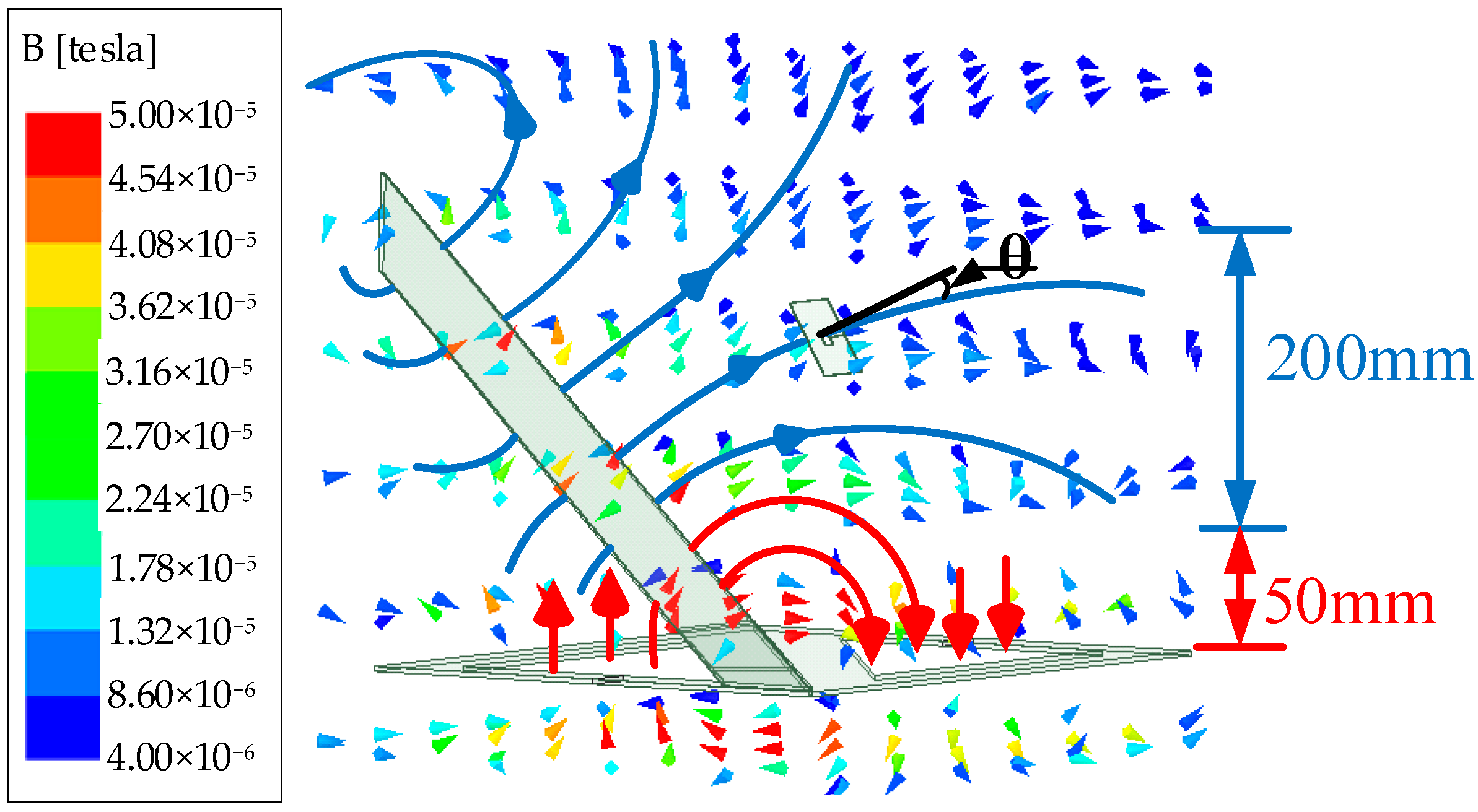
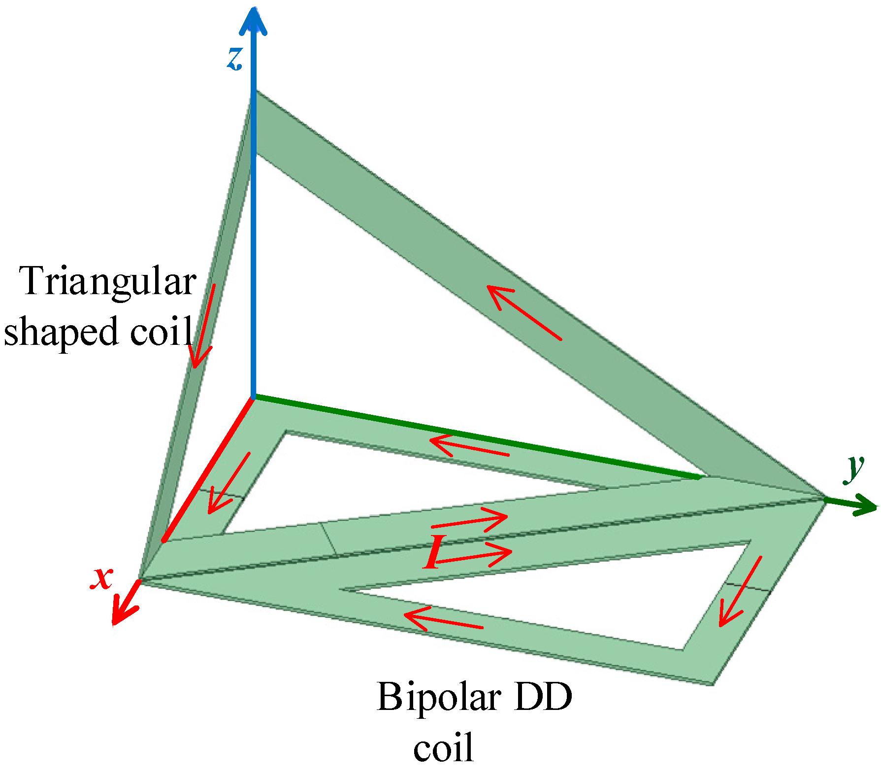
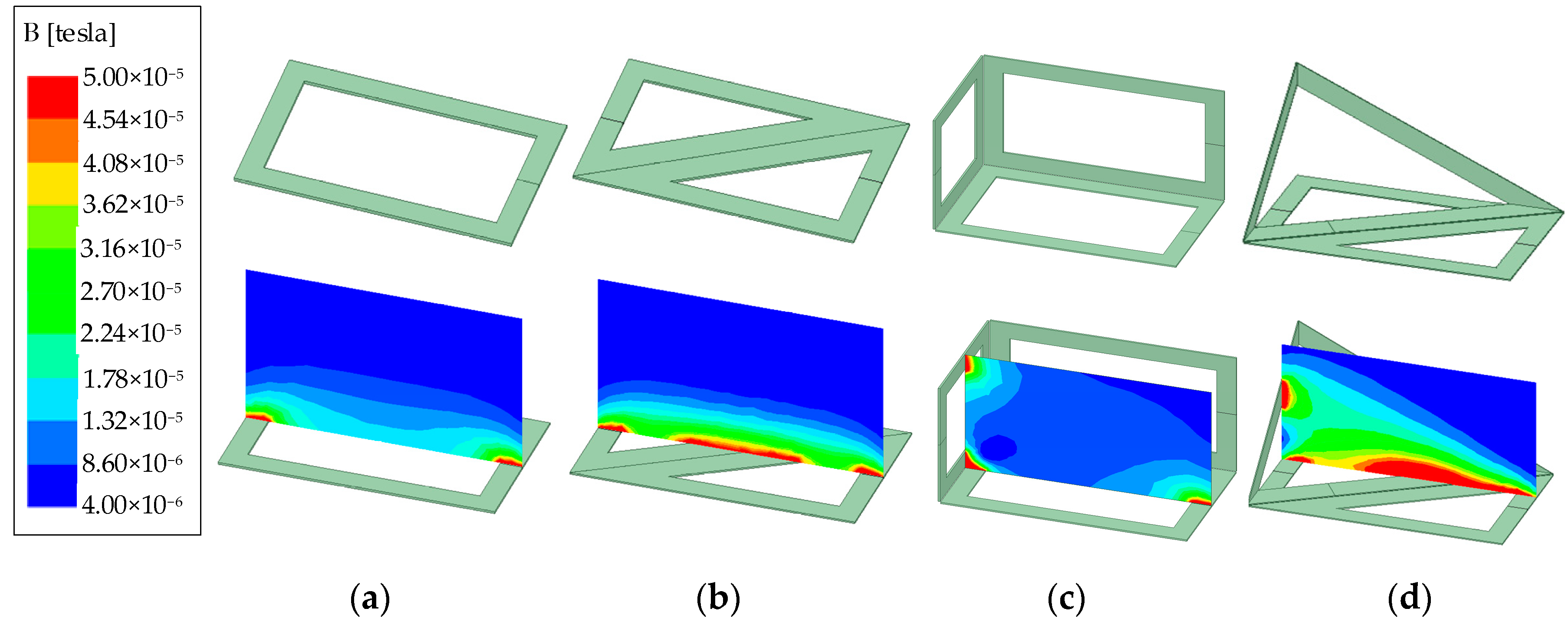
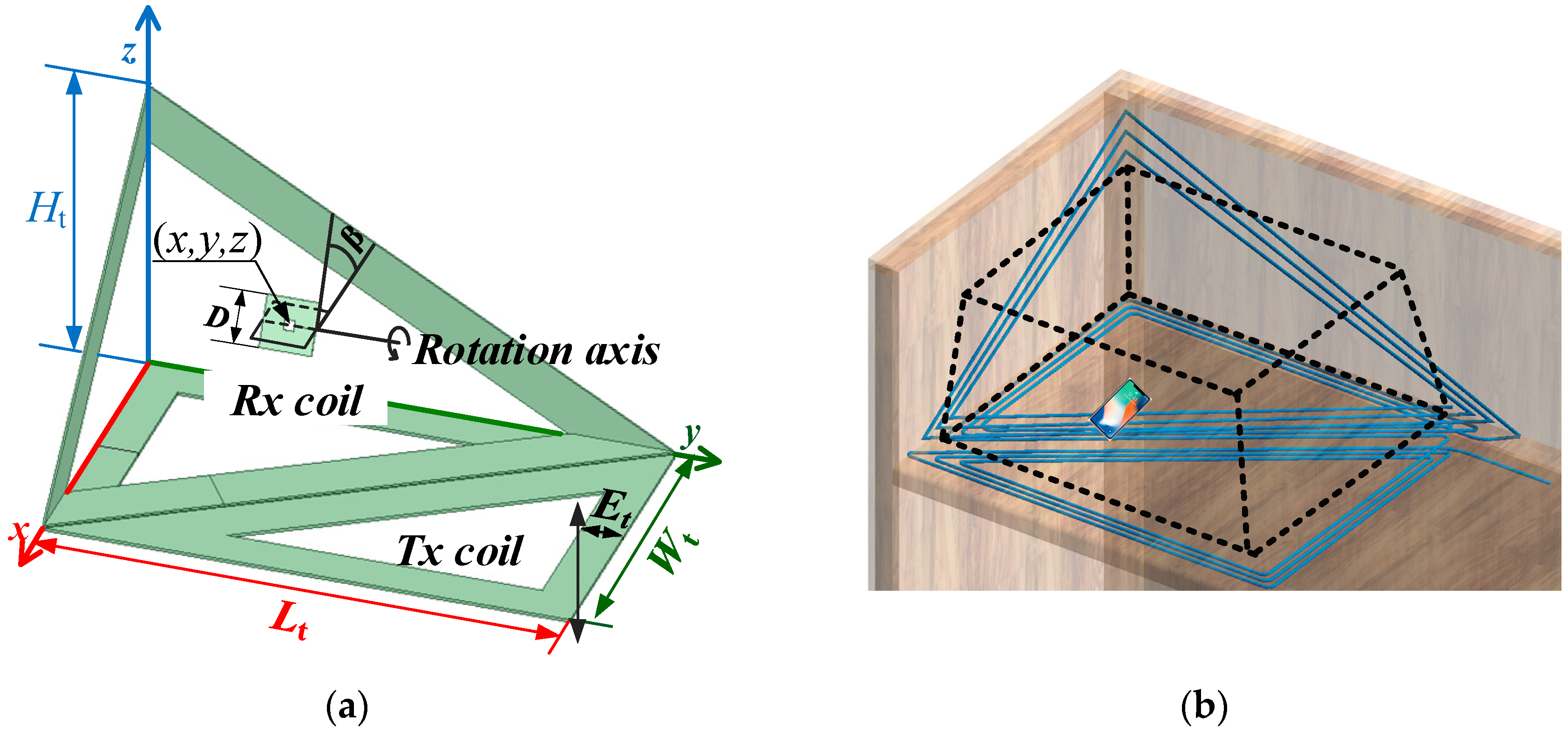
2. Proposed Transmitting Coil

The proposed 3D Tx coil consists of a planar bipolar DD coil and a spatial triangular-shaped coil, which are connected in series. The configuration is described in Figure 1, where the arrow lines denote the direction of current in the Tx coil. The base line of the triangular coil should coincide with the diagonal of the bipolar DD coil. In this way, the magnetic field generated by the two elements will strengthen each other in the whole charging area. Furthermore, the compact Tx coils will not cause any space consumption when embedded in the corner of some office furniture.
For comparison, four different Tx coil models of the same size are established in ANSYS MAXWELL (2017.1.0, Canonsburg, PA, USA), and the magnetic flux density in the YZ vertical section is shown in Figure 2. The current excitations of different coils are set to be the same in the simulations. On the basis of the simulation results of the magnetic flux density of these coils, for the planar concentric spiral coil shown in Figure 2a and the planar bipolar DD coil shown in Figure 2b, the magnetic field density decreases dramatically with the increase of height, which means these planar coils are not appropriate for the spatial WPT. The traditional cubic 3D coils shown in Figure 2c can strengthen the magnetic field density in the higher space. However, the magnetic field density in the lower space is weakened dramatically, especially on the XY plane. This will lead to lower charging efficiency and smaller power capacity when the device is lying flat on the XY plane. In this paper, a novel compact 3D Tx coil shown in Figure 2d is proposed to overcome these drawbacks. From the simulation results, it can be seen that the magnetic flux density is reinforced significantly in the whole charging area.
The simulated magnetic field distribution of the proposed 3D Tx coil is depicted in Figure 3, where θ is the angle between the magnetic field and the normal vector of the Rx coil plane. According to the simulation results, in the charging area, the magnetic field generated by the proposed 3D coils can be roughly divided into two parts: the lower parts (about 0–50 mm) near the XY plane are near-perpendicular to the DD coil; the higher parts (about 50–250 mm) above the XY plane are near-perpendicular to the triangular coil.
Faraday’s law is given as follows:
U EMF = d i = 0 n B S i d x
where B is the magnetic flux density vector, Si is the area of the ith turn of the Rx coil, and n is the turn number of the Rx coil. On the basis of Equation (1), the induced electromotive force (EMF) in the Rx coil can be calculated as follows:
U EMF = d i = 0 n | B r | | S i | cos θ d t
where | B r | is the norm of the magnetic flux density in the position of the Rx coil and | S i | is the area of the ith turn of the Rx coil. For the planar Rx coil, at the fixed working frequency, according to Equation (2), the induced electromotive force (EMF) in the Rx coil just depends on the magnetic flux density | B r | and the angle θ. In consideration of the direction of the magnetic field generated by the proposed 3D Tx coil, whenever the Rx coil is laid flat on the table or held in higher space when the electronics are being used, the angle θ is usually small, which leads to the large value of cos θ . Combined with the strengthened magnetic flux density, a higher induced EMF in the Rx coil is achieved. As a result, the proposed 3D Tx coil can achieve good performance in spatial free-positioning WPT compared with the planar Tx coils and cubic 3D Tx coil.

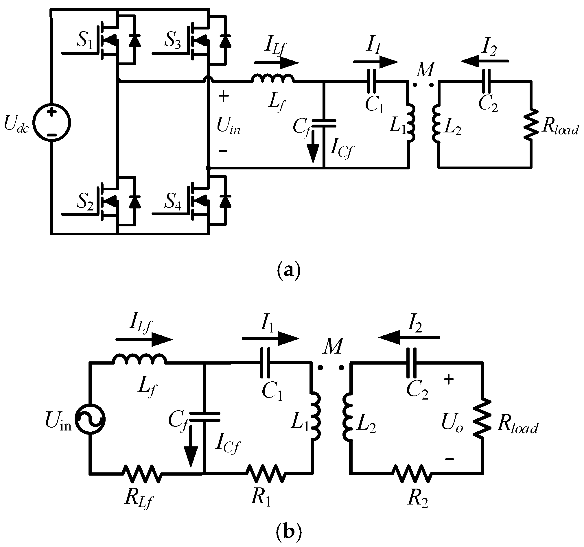
3. Compensation Circuit Design and Analysis

In consideration of the receiver size limitation, series compensation is selected for the receiver side. For the transmitter side, when the receiver moves in the whole charging area, the coupling coefficient will change in a relatively wide range. This change will lead to a significant fluctuation of the current in the transmitter side, including the Tx coil and the inverter, which could cause insecurity.
To eliminate the effect of the wide range of coupling coefficient and realize a constant transmitter current as well as protection of the transmitter side, the LCC compensation is applied for the transmitter side [2]. Therefore, an LCC-S compensation is formed. The topology and equivalent circuit of the wireless charging system with LCC-S compensation is presented in Figure 4.
On the transmitter side, Lf resonates with Cf, which forms the LC parallel resonance. Also, the series reactance of C1 and L1 resonates with Cf, which forms the parallel resonance. On the receiver side, C2 and L2 forms the series resonance. The equations of resonance relationship are given as follows [13]:
ω 0 L f 1 ω 0 C f = 0 ω 0 L 1 1 ω 0 C 1 1 ω 0 C f = 0 ω 0 L 2 1 ω 0 C 2 = 0
where ω0 is the resonant angular frequency.
On the basis of Kirchhoff’s law and the first harmonic approximation (FHA), the equations of the equivalent circuit can be expressed as follows:
{ U in = ( R L f + j ω L f ) I L f + I C f j ω C f = ( R L f + j ω L f ) I L f + ( j ω L 1 + 1 j ω C 1 + R 1 ) I 1 + j ω M I 2 U o = R load I 2 = ( j ω L 2 + 1 j ω C 2 + R 2 ) I 2 + j ω M I 1 I L f = I 1 + I C f
where Uin is the AC voltage output of the inverter, Uo is the load voltage, ω is the angular frequency, R1, R2 are the AC resistance of the Tx coil and Rx coil, respectively, Rload is the load resistance and M is the mutual inductance and can be calculated as follows:
M = k L 1 L 2
Considering the high quality factor of the compensation inductor, from Equation (4), the Tx and Rx coil currents can be calculated as follows:
I 1 = U in j ω L f ,   I 2 = M U in L f ( R 2 + R load )
From Equation (6), it can be seen that the Tx coil current is independent of the coupling and load conditions. The constant Tx coil current can reduce the impact of the dramatic change of the coupling coefficient, protect the Tx side, and simplify the design of the system. From Equation (4) to Equation (6), the coil-to-coil efficiency can be expressed as follows:
η max = C A + B
where
A = R 1 R load + ω 2 M 2 R 2 + R 1 R 2 2 R load B = 2 R 1 R 2 + ω 2 M 2 C = ω 2 M 2
When the coil parameters and the working frequency are determined, we can find that the value of B and C is fixed and the value of A is determined by the load resistance Rload. From Equations (7) and (8), when the smallest value of A is obtained, this leads to the highest coil-to-coil efficiency. Thus, the optimal load resistance can be calculated by Equation (9) to get the highest coil-to-coil efficiency.
R load = ω 2 M 2 R 2 + R 1 R 2 2 R 1

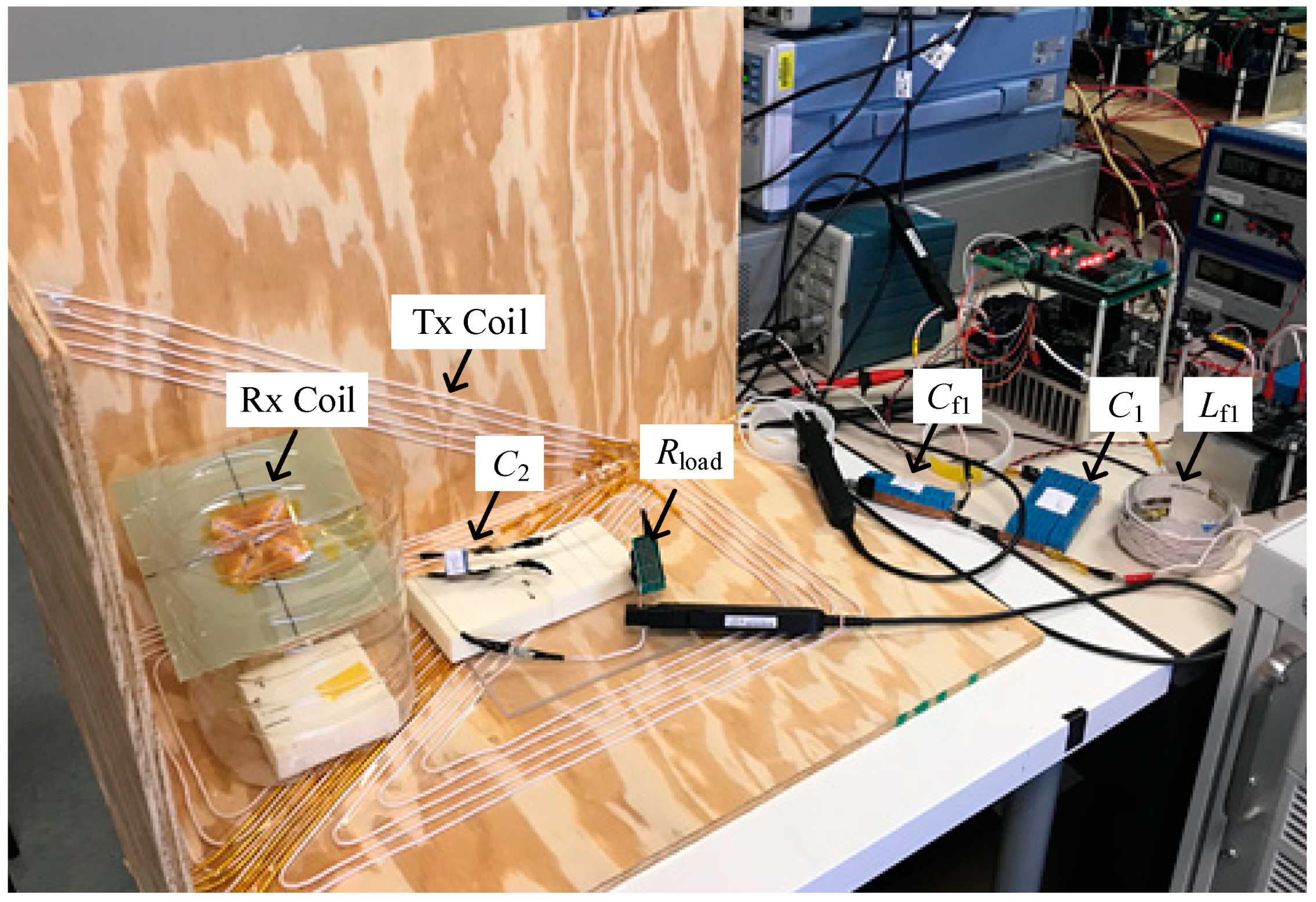
4. Design and Implementation of the System

For verification, the proposed 3D Tx coil is designed and manufactured to form a spatial free-positioning WPT system for mobile phone charging. To increase the transfer efficiency and transfer power, the operating frequency is set to 800 kHz. Figure 5a shows the schematic diagram of the Tx and Rx coils. Lt, Wt, and Ht are the length, width, and height of the transmitter, respectively. Et is the width of the Tx coil and D is the outer diameter of the receiver. The position of the Rx coil is given by (x, y, z) and β, where (x, y, z) are the spatial coordinates of central point of the Rx coil and β is the rotation angle between the Rx coil and the XY plane. The approximate effective charging area (dashed box) of the prototype, where the transmitter can transfer 5 W to the receiver, and an embedded example of the Tx coil are shown in Figure 5b.
It can be seen that such a 3D Tx coil is easy to embed into the corner of an office table. Further, mobile phones can be charged in the working area with great tolerance to positional and angular misalignment.
The optimal dimensions of Tx and Rx coils of the spatial free-positioning WPT experimental prototype are given in Table 1.
The Rx coil is composed of tightly wound AWG 46 Litz wires with a 0.54 mm diameter and are designed as a planar square spiral type with an area of 50 mm × 50 mm, thickness of 0.7 mm, and 20 turns that can be embedded in most mobile phones. The Tx coil is composed of wound AWG 46 Litz wires with a 1.55 mm diameter. The dimension of the Tx coil is designed based on the length-to-width ratio of the working area of a real office table, which is approximately 600 mm × 1000 mm, and the experimental prototype is downsized to 300 mm × 500 mm for easier fabrication. The height of the transmitter Ht and the width Et of the Tx coil is designed and optimized through the simulations of coupling coefficient between the Tx and Rx coils under different Ht and Et in ANSYS MAXWELL to achieve a better coupling between the Tx and Rx coils.
A full-bridge inverter is employed at the transmitter side with silicon carbide power MOSFET C2M0080120D (Wolfspeed, Durham, NC, USA) as the switches. According to the circuit analysis and design of the coils, the optimized load resistance is set to 5 Ω, which is also consistent with the loading conditions of consumer electronics, namely a 5 V/1 A charging state. The compensation inductance and capacitance is designed to realize the LCC-S compensation and the input impedance of the resonance circuit is designed to be inductive to achieve ZVS [2,3]. The specifications of the system are shown in Table 2. On the basis of the design parameters shown in Table 1 and Table 2, the experimental prototype of the spatial free-positioning wireless charging system is fabricated and the setup is shown in Figure 6.

5. Experimental Results and Discussion

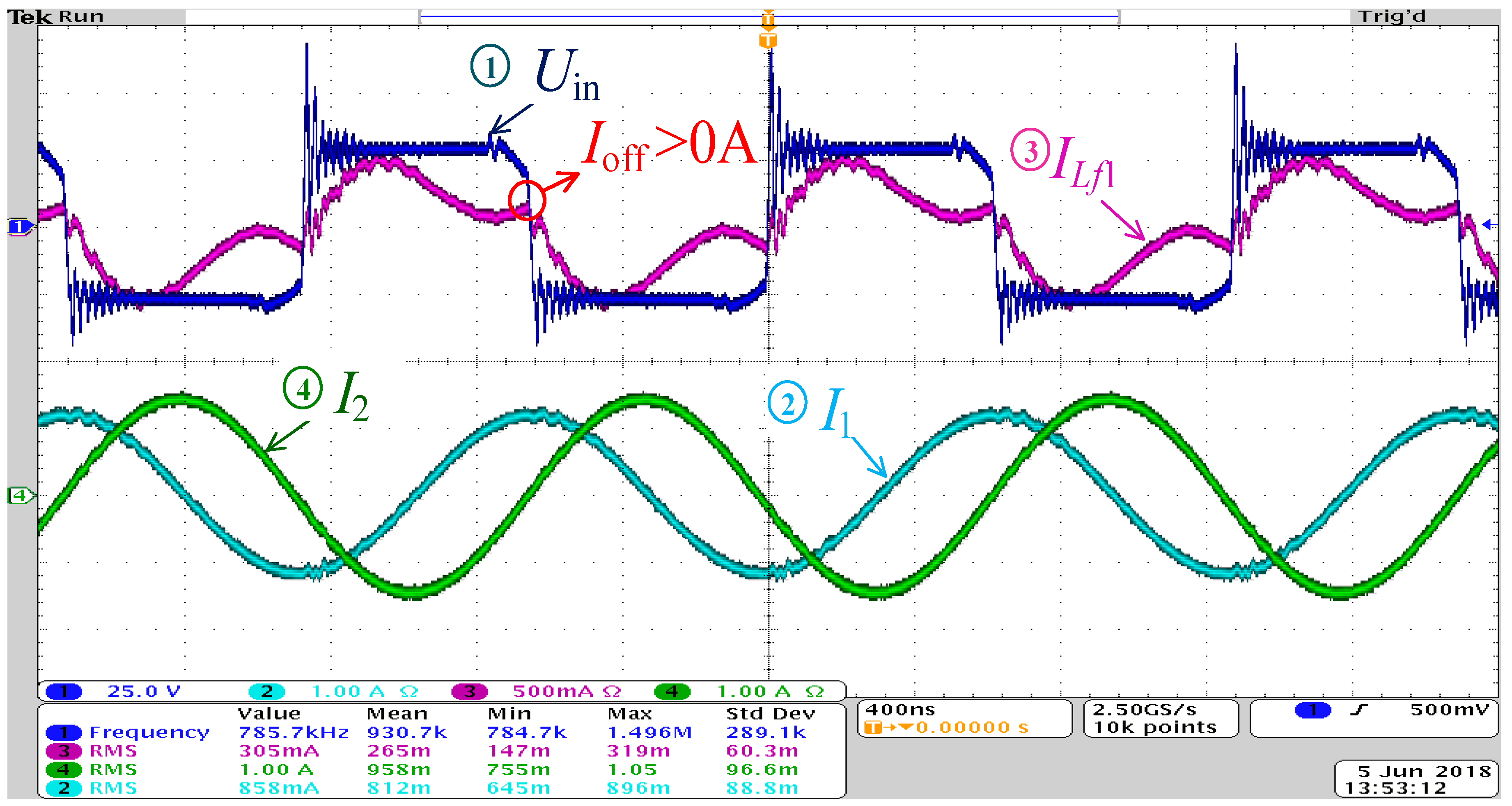
5.1. Performance of H-Bridge High-Frequency Inverter and Compensation Circuit

Figure 7 shows the performance of system in one condition; the other experimental results of waveforms have the same feature and are omitted here. In Figure 7, channel 1 and 3 represent the output voltage and current of the H-bridge high frequency inverter, respectively. Channel 2 and 4 represent the current flowing through the Tx and Rx coil, respectively. From Figure 7, it can be found that the turn-off current Ioff is always larger than zero, which means the output current lags behind the output voltage of the inverter and the MOSFET of the H-bridge works in zero voltage switching (ZVS). From the waveforms of Uin, I1, and I2, we can find that the current flowing through Tx and Rx coil has good sinusoidal properties and Uin leads I1 by almost 90°, which is identical with the theoretical analysis. This means that the compensation circuit works well.

5.2. Output of Power and Efficiency

Thirty-two different positions are chosen as the test points, including eight points flat on the XY plane and others in the air with different rotation angles. The output power and corresponding total efficiency at the test points are shown in Figure 8. The power amplifier (PA) power and efficiency in some conditions are also tested, and the results are shown in Table 3.
From the experimental results shown in Figure 8, we can find that the receiver can receive more than 5 W at most test points. The highest efficiency (77.9%) is achieved when the Rx coil laid flat at (200 mm, 250 mm, 2 mm), and the efficiency decreases to 1.4% at (300 mm, 100 mm, 200 mm) with a rotation angle of 60°, because of the very small coupling coefficient at this point caused by the large transmitting distance and large angle misalignment. From Table 3, it can be seen that the PA efficiency changes from 72.14% to 97.22% and is inversely proportional to the input power, which is because the conduction loss of MOSFET is proportional to current. The relatively small range of variation and high efficiency can show that the ZVS of MOSFET is achieved in all conditions. The coil-to-coil efficiency is also shown in Table 3; it changes with different misalignments and mainly depends on the coupling coefficient between the Tx and Rx coil.
From the experimental results, an effective spatial free-positioning charging area, which is approximately 350 mm × 250 mm × 200 mm, is created by the experimental prototype without any consumption of working space. The average efficiency is 26.6% for the whole effective charging area.

6. Conclusions

A compact spatial free-positioning wireless charging system for consumer electronics using 3D Tx coils has been demonstrated. The novel structure of the proposed 3D Tx coils makes it easy to embed them into some corners of office furniture/cubic panels in such a way that they will not cause any extra space consumption, which is conducive to improving the user experience. The planar Rx coil is designed to match the small size and flat structure of mobile phones. The strengthened magnetic field generated by the novel 3D Tx coils makes it possible to charge consumer devices effectively in a 3D space of 250 mm × 300 mm × 200 mm with a good tolerance of positional and angular misalignment. The ZVS condition for the MOSFETs is realized. The system can achieve the highest efficiency of up to 77.9% and the average efficiency of 26.6% for the whole charging area.

Author Contributions

Conceptualization, Z.L. and Y.Z.; Formal analysis, Z.L. and Y.Z.; Funding acquisition, J.W.; Investigation, Z.L.; Methodology, J.W. and C.M.; Project administration, Z.L., Y.Z., and Z.Y.; Resources, J.J. and Z.Y.; Software, Y.Z.; Supervision, J.W. and C.M.; Writing—original draft, Z.L.; Writing—review & editing, J.W., J.J., and C.M.

Funding

This research was funded by the National Key R&D Program of China (Grant NO. 2017YFB1201003).

Acknowledgments

The authors would like to acknowledge the financial support from the National Key R&D Program of China (Grant NO. 2017YFB1201003).

Conflicts of Interest

The authors declare no conflict of interest.

References

  1. Li, S.Q.; Mi, C.C. Wireless Power Transfer for Electric Vehicle Applications. IEEE J. Emerg. Sel. Top. Power Electron. 2015, 3, 4–17. [Google Scholar]
  2. Li, S.Q.; Li, W.H.; Deng, J.J.; Nguyen, T.D.; Mi, C.C. A Double-Sided LCC Compensation Network and ItsTuning Method for Wireless Power Transfer. IEEE Trans. Veh. Technol. 2015, 64, 2261–2273. [Google Scholar] [CrossRef]
  3. Lu, S.Z.; Deng, X.T.; Shu, W.B.; Wei, X.C.; Li, S.Q. A New ZVS Tuning method for Double-Sided LCC Compensated Wireless Power Transfer System. Energies. 2018, 11, 307–320. [Google Scholar]
  4. Seol, W.-K.; Chung, S.-K. Current Vector Control of Wireless Power Transfer System with 2D Tx Coils. Electron. Lett. 2018, 54, 91–93. [Google Scholar] [CrossRef]
  5. Ng, W.M.; Zhang, C.; Lin, D.Y.; Hui, S.Y.R. Two- and Three-Dimensional Omnidirectional Wireless Power Transfer. IEEE Trans. Power Electron. 2014, 29, 3252–3272. [Google Scholar] [CrossRef]
  6. Zhang, C.; Lin, D.Y.; Hui, S.Y. Basic Control Principles of Omnidirectional Wireless Power Transfer. IEEE Trans. Power Electron. 2015, 31, 5215–5227. [Google Scholar]
  7. Kim, J.; Son, H.-C.; Park, Y.-J. Multi-loop Coil Supporting Uniform Mutual Inductances for Free-Positioning WPT. Electron. Lett. 2013, 49, 417–419. [Google Scholar] [CrossRef]
  8. Ha-Van, N.; Seo, C. Analytical and Experimental Investigations of Omnidirectional Wireless Power Transfer Using a Cubic Transmitter. IEEE Trans. Ind. Electron. 2018, 65, 1358–1366. [Google Scholar] [CrossRef]
  9. Zhang, W.; Zhang, T.Y.; Guo, Q.Q.; Shao, L.M.; Zhang, N.B.; Jin, X.L.; Yang, J. High-Efficiency Wireless Power Transfer System for 3D, Unstationary Free-Positioning and Multi-Object Charging. IET Electr. Power Appl. 2018, 5, 658–665. [Google Scholar] [CrossRef]
  10. Choi, B.H.; Lee, E.S.; Sohn, Y.H.; Jang, G.C.; Rim, C.T. Six Degrees of Freedom Mobile Inductive Power Transfer by Crossed Dipole Tx and Rx Coils. IEEE Trans. Power Electron. 2016, 31, 3252–3272. [Google Scholar] [CrossRef]
  11. Feng, J.J.; Li, Q.; Lee, F.C. Omnidirectional Wireless Power Transfer for Portable Devices. In Proceedings of the IEEE Applied Power Electronics Conference and Exposition (APEC), Tampa, FL, USA, 18 May 2017; pp. 1675–1681. [Google Scholar]
  12. Mirbozorgi, S.A.; Jia, Y.Y.; Canales, D.; Ghovanloo, M. A Wirelessly-Powered Homecage with segmented copper foils and closed-loop power control. IEEE Trans. Biomed. Circuits Syst. 2016, 10, 979–989. [Google Scholar] [CrossRef] [PubMed]
  13. Yan, Z.C.; Zhang, Y.M.; Song, B.W.; Zhang, K.H.; Kan, T.Z.; Mi, C.C. An LCC-P Compensated Wireless Power Transfer System with a Constant Current Output and Reduced Receiver Size. Energies. 2019, 12, 172. [Google Scholar] [CrossRef]
Figure 1. Configuration of the proposed 3D Tx coil.
Energies 12 01409 g001
Figure 2. Different Tx coils with their respective magnetic field density simulations in the YZ vertical section. (a) Concentric spiral coil. (b) Bipolar DD coil. (c) Cubic 3D coil. (d) Proposed 3D coil.
Energies 12 01409 g002
Figure 3. Simulated magnetic field distribution of the 3D Tx coil.
Energies 12 01409 g003
Figure 4. Wireless charging system with inductor–capacitor–capacitor and series (LCC-S) compensation. (a) Topology. (b) Equivalent circuit.
Energies 12 01409 g004
Figure 5. Spatial free-positioning wireless power transfer (WPT) prototype. (a) Schematic diagram of the Tx and Rx coils. (b) Embedded-design of 3D Tx coil and approximate charging area.
Energies 12 01409 g005
Figure 6. Manufactured experimental prototype of the spatial free-positioning wireless charging system.
Energies 12 01409 g006
Figure 7. Experimental results of waveforms of the input and output of the coupling resonator.
Energies 12 01409 g007
Figure 8. Output power and efficiency of the prototype.
Energies 12 01409 g008
Table 1. Optimal dimensions of the experimental prototype.
SymbolQuantityValue
LtLength of Transmitter500 mm
WtWidth of Transmitter300 mm
HtHeight of Transmitter300 mm
EtWidth of Tx coil40 mm
DEdge length of Rx coil50 mm
Table 2. Spatial free-positioning wireless charging system specification.
SymbolQuantityValue
UdcmaxMaximum input DC voltage300 V
kCoupling coefficient0.004–0.06
L1Tx coil inductance31 μH
L2Rx coil inductance13.6 μH
LfTx-side compensation inductance 6.27 μH
CfTx-side parallel compensation capacitance 6.51 nF
C­1Tx-side series compensation capacitance1.63 nF
C2Rx-side series compensation capacitance3 nF
R1Tx coil AC resistance 0.6 Ω
R2Rx coil AC resistance1 Ω
fSwitching frequency800 kHz
RloadLoad resistance5 Ω
Table 3. Power amplifier (PA) power and efficiency with different positional and angular misalignment of receiver.
Position and Angle of Test PointPA power (W)PA EfficiencyCoil-to-Coil EfficiencyTotal Efficiency
x (mm)y (mm)z (mm)β (°)InputOutput
1001002010.6710.32796.79%48.46%46.90%
1002502013.3111.31284.99%44.12%37.50%
3001002053.9238.972.14%12.89%9.30%
300250207.2727.0797.22%70.77%68.80%
2001001003039.19232.8983.92%15.25%12.80%
2002001003030.2827.0589.33%18.47%16.50%
2001001006029.69425.7186.58%19.40%16.80%
2002001006031.98327.8286.98%17.93%15.60%
2001002003057.51245.13278.47%11.09%8.70%
2002002003085.60266.1977.32%7.50%5.80%
2001002006080.61960.5375.08%22.38%16.80%
2002002006058.8946.4478.86%19.78%15.60%

