Abstract
Scramjet based on solid propellant is a good supplement for the power device of future hypersonic vehicles. A new scramjet combustor configuration using solid fuel, namely, the solid fuel rocket scramjet (SFRSCRJ) combustor is proposed. The numerical study was conducted to simulate a flight environment of Mach 6 at a 25 km altitude. Three-dimensional Reynolds-averaged Navier–Stokes equations coupled with shear stress transport (SST) turbulence model are used to analyze the effects of the cavity and its position on the combustor. The feasibility of the SFRSCRJ combustor with cavity is demonstrated based on the validation of the numerical method. Results show that the scramjet combustor configuration with a backward-facing step can resist high pressure generated by the combustion in the supersonic combustor. The total combustion efficiency of the SFRSCRJ combustor mainly depends on the combustion of particles in the fuel-rich gas. A proper combustion organization can promote particle combustion and improve the total combustion efficiency. Among the four configurations considered, the combustion efficiency of the mid-cavity configuration is the highest, up to about 70%. Therefore, the cavity can effectively increase the combustion efficiency of the SFRSCRJ combustor.
1. Introduction
The applications of hypersonic vehicles include high-speed transport, space access etc. Scramjet is a kind of ideal propulsion system for hypersonic flight (Ma > 5). More and more research is being conducted in the scramjet field due to the important scientific significance and application value [1,2,3,4,5,6,7]. At the same time, because of the complex measurement system and costly experimental apparatus, computational fluid dynamics (CFD) on the scramjet has attracted the attention and appreciation of scientists [8,9,10,11,12,13,14].
Currently, the research process of scramjets is mainly focused on liquid fuel, such as kerosene and liquid hydrogen [8,11,14,15,16,17,18]. However, compared with the liquid fuel scramjets, solid fuel scramjets have the same advantages as traditional solid fuel engines, such as simple structure, high energy density, good maneuverability, and long storage time, etc. Therefore, the solid fuel scramjet has gradually developed in the recent decades [13,19,20,21,22,23,24,25,26,27,28,29,30,31]. Main achievements of the solid fuel scramjet are summarized below.
In 1989, Witt [27] et al. firstly conducted a preliminary experimental study on the feasibility of scramjet using solid fuel. The results demonstrated that solid fuel (PMMA) can be burned in a supersonic flow by adding a bit of hydrogen as the pilot torch. Therefore, a combustor configuration was proposed, namely, the solid fuel scramjet (SFSCRJ) combustor. On the basis of Witt’s research, Angus [19] further studied the performance of the SFSCRJ combustor experimentally. He reported that the combustion efficiency was 57% and demonstrated the feasibility of SFSCRJ once again. Later, Ben-Yakar et al. [21,22] achieved self-ignition and self-sustained combustion in the SFSCRJ combustor without external aid. The schematic of SFSCRJ is displayed in Figure 1. A cavity was used as a flame holding device in the experiments. Moreover, Saraf and Gany [32] studied the effects of solid fuel with metal powder aluminum on the performance of the SFSCRJ combustor. It concluded that adding metal powder can increase specific thrust but decrease specific impulse. Hu et al. [31] carried out a numerical investigation to study the characteristics of CSFSCRJ (combined solid fuel scramjet). The results showed that the total pressure recovery and the combustion efficiency was 35% and 48%, respectively. Wang et al. [24,25] conducted numerical and experimental studies on the specific thrust level and variation rule in the solid fuel scramjet combustor. The results pointed out that the specific thrust could reach about 600–800 N/kg·s in the preconcerted flight conditions, and the specific thrust decreased with the total pressure recovery increase during the operating process.
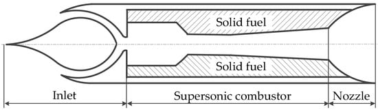
Figure 1.
Schematic of solid fuel scramjet (SFSCRJ).
The previous research has demonstrated the feasibility of the SFSCRJ. However, its limitations are evident:
- (1)
- Self-ignition and flame stabilization are difficult.
- (2)
- The inner surface of the combustor varies with the fuel regression, thus possibly affecting the overall performance of the SFSCRJ.
- (3)
- The air–fuel ratio depends on fuel regression rate, which cannot be controlled directly and actively.
- (4)
- Combustion efficiency of solid fuel is too low because of the low mixing efficiency and short residence time.
In order to solve the problems mentioned above, Lv et al. [26] proposed a new scramjet configuration, namely, the solid-fuel rocket scramjet (SFRSCRJ), as shown in Figure 2. The configuration is composed of four parts, namely inlet, solid-fuel gas generator, supersonic combustor, and nozzle, respectively. The propellant is fuel-rich solid fuel, containing a bit of oxidizer to maintain self-sustained combustion in the gas generator. The primary combustion in gas generator does not need oxygen from incoming air. Therefore, the installation location is flexible. The fuel-rich gas is injected into the supersonic combustor for secondly mixing and combustion with air, which contributes to improve the combustion efficiency compared with the boundary layer diffusion combustion of SFSCRJ. Finally, the thrust is generated through the expansion of the nozzle. The mass flow rate of the fuel-rich gas can be controlled by a designed throat, so the air-fuel ratio is easy to regulate. The results of the experiments show that the scramjet configuration using solid fuel is feasible, and the total pressure loss and combustion efficiency is 50% and 65%, correspondingly.
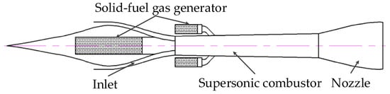
Figure 2.
Schematic of SFRSCRJ.
The mainstream remains supersonic in a scramjet. Thus, the residence time of air and fuel gas is about 1 ms. For the sake of an effective and stable combustion at such a short time, many methods have been adopted to achieve mixing enhancement and flame holding. In the past several decades, the cavity has been studied in the scramjet field. A structure that can generate a subsonic recirculation zone can increase the residence time of fuel in a supersonic combustor, promote the mixing between fuel gas and airflow, and play a role in flame holding. Currently, the cavity is mainly used in the liquid fuel scramjet [33,34,35,36]. Pei and Hou [37] studied the influences of cavity length/deep ratio on the performance of combustor in a SFSCRJ. The results showed that the combustion efficiency of the supersonic combustor is the highest for an appropriate cavity length/deep ratio of 4 with moderate total pressure loss. But few studies have carried out using the cavity in the SFRSCRJ, and the mechanism of the cavity on the gas-solid two-phase flow remains unclear.
In the following numerical study, a new configuration, namely, the single-side expanded SFRSCRJ combustor is proposed, as displayed in Figure 3. This combustor consists of three parts: Isolator, supersonic combustor with a cavity, and gas generator. The goal of this paper is to obtain the effects of the cavity on the SFRSCRJ combustor. In Section 2, the numerical model and method, model validation and grid independence analysis are introduced. In Section 3, the characteristics of the without-cavity configuration are discussed in detail. Then, the effects of cavity on the scramjet combustor from three aspects, namely, flow field characteristics, particle combustion characteristics and combustor performance, are illustrated. Several helpful conclusions are drawn to provide a basis for the further experimental study.
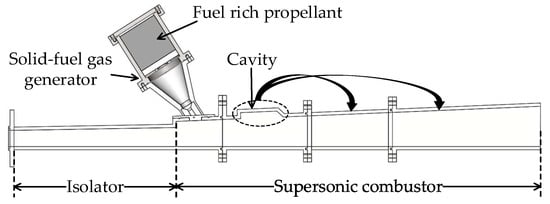
Figure 3.
Single-side expanded SFRSCRJ combustor.
2. Numerical Model and Method
Fuel-rich gas is produced by the primary combustion of a solid propellant within the gas generator. The composition of the fuel-rich gas is quite complex. In addition to the gas-phase products, there are large amounts of condensed products, such as carbon particle. The fuel-rich gas is mixed with the supersonic flow after entering the supersonic combustor, thereby presenting complex 3D two-phase turbulent combustion characteristics. The models to be considered for the process include turbulence, particle motion, and combustion models.
2.1. Governing Equations
The gas-phase flow and combustion governing equations in the SFRSCRJ combustor are described by the Reynolds-averaged Navier–Stokes equations together with the mass, momentum, energy, and species transport equations [38], which are expressed as follows, respectively:
where the notations of and stand for time average and Favre average (Favre average is for variable density flow, e.g., combustion, such as the condition in this paper). The , and represent the density, velocity and pressure, correspondingly. The , and represent the temperature, total enthalpy and reaction heat, respectively. The terms in each equation represent the source term, for example gas-solid two-phase interaction, body force or radiation. The is the mass fraction of species . The and are the binary mass diffusion coefficient between species and thermal conductivity coefficient, which refer to Fick’s law of mass diffusion and Fourier’s law of heat conduction, correspondingly. The is the viscous stress component, which can be related to strain rate as:
where
where is the strain rate tensor, and is the molecular viscosity.
The turbulent enthalpy flux, , and the turbulent species flux, are often described using gradient diffusion assumption as follows:
where , are the turbulent Prandtl and Schmidt number, and are normally set as constant around unity.
Then the remaining unclosed in the RANS equations are Reynolds stress, , and the averaged reaction source term, , which are closed by using the turbulence and combustion models, respectively.
2.2. Turbulence Model and Numerical Method
In order to get detailed flow parameters, Fluent 15.0 is used to simulate the 3D flow field of the SFRSCRJ combustor. The computing domain is solved iteratively with an implicit density-based double-precision solver. The shear stress transport (SST) turbulence model [39,40] is employed to enclose the governing equations mentioned above. This model provides high computational accuracy for both the free shear layer and the moderate separation flow turbulence. A second-order upwind difference scheme is used to discretize the convective terms, whereas a second-order center difference scheme is used for diffusion terms.
2.3. Particle Motion Model
Although the fuel-rich mixture contains a certain mass fraction of condensed products, the volume concentration of the condensed phase is far less than 1%. Therefore, the discrete random walk model is used to track the particles orbits in the SFRSCRJ combustor.
The kinetic equations of the particle in the Cartesian coordinate system are described as follows:
where is the particle position vector, is the particle velocity vector, is the resistance to unit mass particles, and represents other external forces on the particles, such as body force and Stephen flow.
Resistance per unit mass of particles is defined by:
where is the gas velocity vector, and represent the particle density and diameter, respectively; and is the drag coefficient, which can be written as follows:
where is the particle Reynolds number determined from:
where is the gas density, and is the dynamic viscosity coefficient.
2.4. Combustion Model
The components and flow parameters of fuel-rich gas are calculated by the National Aeronautics and Space Administration’s Chemical Equilibrium with Application (CEA) software [41]. The results show that the combustible components of the fuel-rich gas are , , , and carbon particles. The gas-phase combustion model uses the finite-rate/eddy-dissipation model. This model considers both effects of turbulence diffusion and chemical reaction on combustion simultaneously. Three single-step overall reaction mechanisms are used for gas-phase reaction:
where the pre-exponential factor and activation energy for the three reactions mentioned above (Equations (14)–(16)) are 2.239 × 10¹², 9.87 × 10⁸, 2.119 × 10¹¹, and 1.7 × 10⁷, 3.1 × 10⁷, 2.027 × 10⁸, correspondingly [42].
The carbon particles combustion model adopts the improved moving flame front (MFF) model by Zhang [43]. A user-defined function is written to calculate the improved MFF model into the solver. The explicit expressions of the carbon particles combustion rate in the MFF model are expressed as:
where is the surface combustion rate of carbon particles; and are the diffusion rate coefficient of and , respectively; and are the diffusion rate coefficient of and on the particles’ surface, correspondingly; and are the pressure of and , respectively.
2.5. Model Validation and Grid Independence Analysis
The experiment of configuration shown in Figure 4 is simulated to validate the numerical model and method. The experiment has been conducted previously by our team. The 3D structure grid is generated by the ICEM software (ANSYS Inc, USA). The part is where the parameters change violently and the near wall are encrypted. The boundary conditions are summarized in Table 1 and they are the same as the experiment.
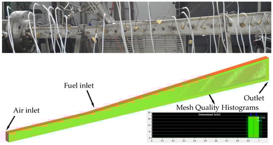
Figure 4.
Grid in the computing domain.

Table 1.
Boundary conditions.
Pressure distribution curve along the combustor is depicted in Figure 5. It is obvious that the trend of numerical pressure distributions is consistent with that of the experiment. Small deviation is observed because the initial combustion products are obtained by the CEA thermal computing software [41], and the particles’ diameter is the uniform size distribution according to the range mentioned in Ref [44]. Nevertheless, the overall pressure distribution curve of the numerical results agrees well with the experiment data. It indicates that the numerical method used in this work has certain applicability, and can be employed to simulate the flow field under these conditions.
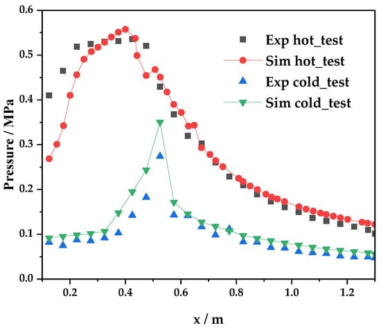
Figure 5.
Comparison of experimental and numerical pressure distributions along the combustor.
Based in the model validation, grid independence analysis is carried out. Wall static pressure distributions at x = 150 mm are selected to verify grid independence, and the results are given in Figure 6. The coarse grid has about 0.4 million cells, whereas the moderate and fine grids have about 1.6 and 2.2 million cells, respectively. The differences between results for the coarse and moderate grids is evident. However, the results of the moderate and fine grids almost overlap with each other. Considering the computational accuracy and the cost, the moderate grid is enough for numerical simulation.
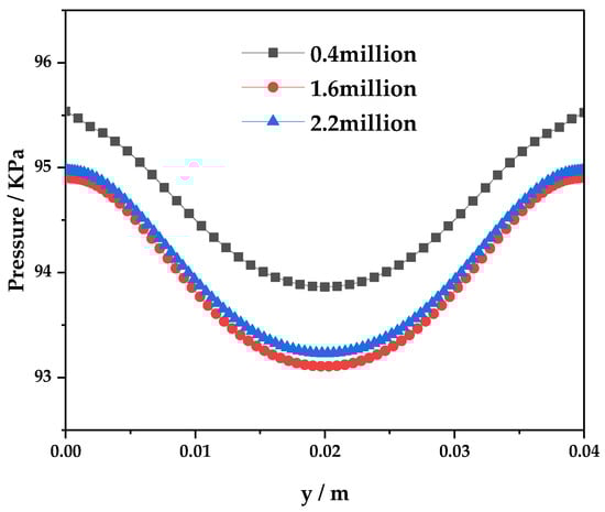
Figure 6.
Grid independence analysis
3. Results and Discussion
3.1. Physical Model and Boundary Conditions
The physical model is exhibited in Figure 7. The length of the isolator and supersonic combustor is 400 and 900 mm, correspondingly. The height and width of air inlet are 40 and 50 mm, respectively. The isolator takes a divergence angle of 1° for correcting the boundary layer effect, whereas the supersonic combustor takes a divergence angle of approximately 2.37° to maintain supersonic flow. The height of the back-ward-facing step is 15 mm. The length-to-depth ratio of the cavity is 7, and the 45° ramp angle at the end of the cavity is used to suppress oscillations [33].
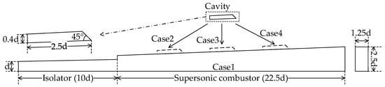
Figure 7.
Physical model.
Table 2 displays the correspondence between the configuration and the index. The configuration without cavity is Case 1. And the Case 2, 3, 4 represent the configuration index for front-cavity, mid-cavity and back-cavity, correspondingly. The geometric model of the front-cavity configuration is presented in Figure 8. The mesh domain of the fuel inlet is generated by the O-block of the ICEM. The mesh quality of the grid as illustrated in the lower right corner of Figure 8, indicating that the overall quality of the grid is favorable.
Table 2.
Configuration index.
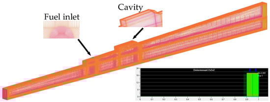
Figure 8.
The geometric model of the front-cavity configuration.
The fuel-rich solid propellant is used in the numerical simulation. The design flight environment is 25 km and Ma6, and the equivalence ratio is 0.5. Therefore, the mass flow rate of fuel-rich gas can be determined from the following equation:
where and are the real and stoichiometric air-fuel ratio, respectively, which can be calculated with the CEA thermal computing software [41].
The fuel-rich gas components also can be obtained by the CEA thermal computing software [41]. The simplified thermal calculation results are summarized in Table 3. And the boundary conditions are summarized in Table 4.
Table 3.
Fuel-rich gas components.
Table 4.
Boundary conditions.
3.2. Without-Cavity Configuration Analysis
The upper left of Figure 9 displays the typical schematic of a transverse jet in a supersonic flow [45,46]; the two other images refer to the temperature contours in the overall combustor and near the backward-facing step. The main averaged flow features around the transverse jet, such as the counter-rotating vortex pair, bow shock, and Mach disk, were captured. It indicates that the numerical method used in the paper can simulate the flow field in the supersonic combustor. There is a high temperature region in the vicinity of the backward-facing step shown in the upper right of Figure 9. It is beneficial for secondary ignition and flame holding. The high temperature region is mainly distributed on the upper wall because of the single side expansion, indicating the combustion near the upper wall is violent.
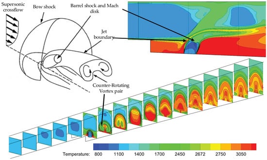
Figure 9.
Schematic of a transverse jet in a supersonic crossflow.
Figure 10 displays the contours of carbon particle residence time, temperature, and mass. In Figure 10A, the maximum residence time is about 1 ms. It is difficult for carbon particles to achieve complete combustion in that short time. The carbon particle temperature and mass contours are shown in Figure 10B,C, respectively. It can be seen that there is a distinct temperature gradient and a small mass gradient in the marked domain. It is evident that the big temperature gradient is caused by gas phase combustion not the particles combustion. Therefore, combustion competition must exist between the gas phase and the particles. Of course, the high temperature generated by gas phase combustion in this zone can preheat the carbon particles, thereby providing a faster initial reaction rate for subsequent particles combustion.
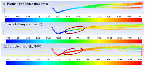
Figure 10.
Without-cavity configuration carbon particles contours.
3.3. Flow Field Characteristics
Figure 11 exhibits the average pressure distribution along the combustor of different configurations. The pressure of combustors does not affect the isolator pressure because of the backward-facing step, which is beneficial to the start of the inlet. The pressures of the four configurations rise sharply near the fuel inlet. It is caused by the mixing and combustion of the fuel-rich gas and airflow. After the fuel inlet, pressure was floating back and forth, which is due to combustion violently and complex shock waves. The overall pressure distribution of the mid-cavity configuration is higher, as displayed in Figure 11. Therefore, a more intense combustion occurs in the mid-cavity combustor. The temperature contours of the symmetry planes of each configuration are presented in Figure 12. The backward-facing steps still play the role of flame holding, as mentioned in the without-cavity configuration analysis. The high-temperature areas in the three other combustors are larger than the without-cavity configuration. Thus, the cavity can enhance the mixing and combustion of primary fuel-rich gas and airflow. Furthermore, it can maintain a relatively high temperature in the vicinity of the cavities because of the low velocity reflux zone, which contributes to the combustion of the fuel-rich gas. Figure 12 also illustrates that, among the four configurations, the mid-cavity configuration has the largest heat release zone. However, the heat release zone of the three other configurations is relatively small. Therefore, the mid-cavity configuration is more effective for the overall heat release of the flow channel.
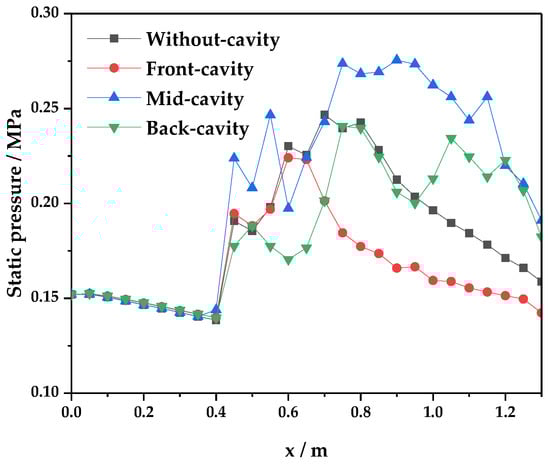
Figure 11.
Average pressure distributions along the combustor.
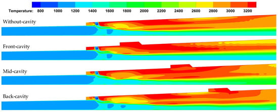
Figure 12.
Symmetry plane temperature contours
The average Mach number distribution along the combustors of different configurations are illustrated in Figure 13. The Mach number decreases sharply at the isolator exit because of the flow channel expansion and heat release. Equation (20) [4] describes that Mach number along the combustor changes with total temperature and flow channel area. The Mach number is up or down in a supersonic combustor depending on the contest between the flow channel expansion and combustion heat release. In Figure 13, except for the mid-cavity configuration, the flow channels of the three other maintain supersonic combustion. It indicates that the average heat release of the mid-cavity configuration is more violent. A small local subsonic zone is observed in the mid-cavity configuration. However, after the Ma is less than 1, the comprehensive effects of boundary layer, addition of heat and mass, and the expansion of flow channel make the Ma increase gradually to 1. And the gas maintains supersonic flow at the exit of the combustor.
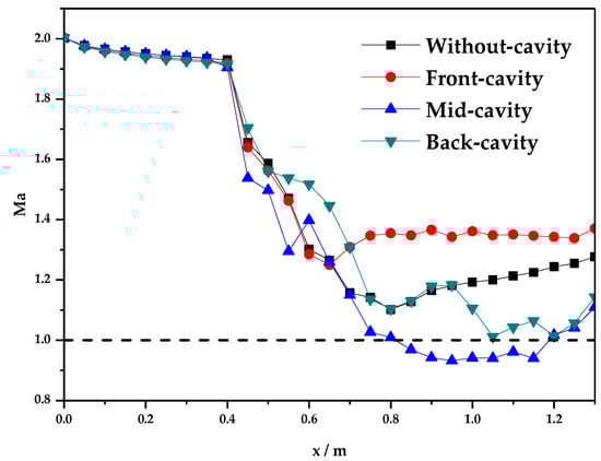
Figure 13.
Average Mach number distributions along the combustor.
3.4. Particle-Phase Combustion Analysis
From the previous analysis, the fuel-rich gas generated from gas generator contains a certain mass fraction of the carbon particles. Moreover, the heat value of carbon particles is high. If the carbon particles can be burned completely, the combustion efficiency of the solid fuel can be improved a lot. Figure 14 depicts the carbon particle residence time contours for different cases. The mid-cavity and back-cavity configurations can change the orbits of partial particles in the combustor to extend the residence time, thereby increasing the particle combustion efficiency.
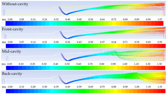
Figure 14.
Carbon particles residence time contours.
The combustion efficiency of the carbon particles is defined as:
where and are the total carbon particle masses in the fuel inlet and outlet, respectively.
Figure 15 exhibits the longest residence time and the combustion efficiency of carbon particles for the four cases. Compared with the without-cavity configuration, the combustion efficiency of the particle phase is improved. Although the residence time is shorter in the front-cavity configuration than that in the back-cavity configuration, the combustion efficiency of the former is high. That is because preheating particles is more important than long residence time in terms of combustion efficiency. A simplified mathematical illustration can be seen in the next part. The particle combustion efficiency is highest in the mid-cavity configuration, which is caused by the comprehensive effects of preheating particles and longer residence time. The increase in both reaction temperature and time can promote particle combustion. However, the role of the former is more important than the latter in a limited length of the combustor.
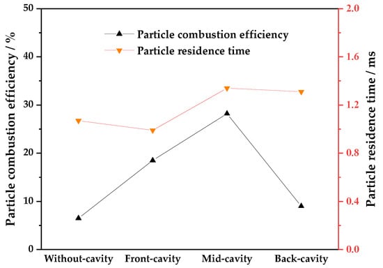
Figure 15.
Residence time and combustion efficiency of carbon particles.
3.5. Combustor Performance
The total combustion efficiency is defined as the combustion efficiency of all combustible components injected into the combustion chamber. The expression is
where , , and are the mass fractions of , , and , correspondingly. , , , and represent the combustion heat of carbon particle, , , and, respectively.
The total pressure loss in the SFRSCRJ combustor is caused by boundary layer, flow separation, shock waves, and fuel-air mixing and combustion. The total pressure recovery coefficient is determined from
where is the total pressure at a certain x-axis position, and is the total pressure of air inlet.
The total combustion efficiency and total pressure recovery of the four cases is exhibited in Figure 16. The total combustion efficiency of the mid-cavity configuration is the highest. In comparison with the without-cavity configuration, the total combustion efficiency of the mid-cavity is increased by about 8.8%. In addition, the front- and back-cavity configurations are also increased by about 4.8% and 1%, correspondingly. However, the total pressure recovery of four configurations almost have no distinct difference.
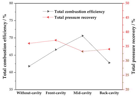
Figure 16.
Total combustion efficiency and total pressure recovery.
In the numerical simulation, the gas phase product is burned completely, and the total combustion efficiency mainly depends on the combustion of the particles. A simplified global one-step reaction mechanism is used for combustion efficiency analysis of the carbon particle as follows:
The combustion rate of carbon particles in the global reaction can be defined by the following formula:
where is the reaction rate constant; is the oxygen concentration; and m is the reaction order of the oxygen in the global reaction; and , , , and represent the pre-exponential factor, activation energy, universal gas constant, and reaction temperature, respectively.
Therefore, the combustion efficiency of carbon particles in flow field can be defined as
where and represent the number of particles and the number of mesh cells that passed by a certain particle, correspondingly, is the molecular weight of carbon particle, is the volume of a certain grid cell, and represent the residence time of a certain particle in a certain cell .
The temperature and residence time affect combustion efficiency. Temperature is an exponential form, whereas residence time is only a linear form. Therefore, establishing a large high-temperature area is more effective than increasing the residence time to improve the combustion efficiency.
4. Conclusions
In this paper, a new scramjet combustor configuration using solid fuel, namely, SFRSCRJ combustor with cavity, is proposed. The influence of the cavity and its position on the performance of the SFRSCRJ combustor is studied. By analyzing the flow field characteristics and evaluating the combustor performance, the cavity for the SFRSCRJ combustor is demonstrated to be feasible. The main conclusions are summarized as follows:
- The combustor configuration with a backward-facing step is resistant to combustor pressure. This situation is beneficial for the start of the inlet.
- A competition occurs between the particle and the gas phase combustion near the fuel inlet. However, the high temperature generated by the gas phase combustion can accelerate the subsequent particle combustion.
- The increase in both the residence time and the combustor temperature can improve the combustor performance. Nevertheless, increasing reaction temperature is more effective than the residence time.
- Generally, the gas phase combustion is relatively complete. The total combustion efficiency mainly depends on the combustion efficiency of the particle-phase. The combustion efficiency of the mid-cavity configuration reaches about 70% and is the highest among the four configurations. However, all configurations display almost the same total pressure loss.
Several helpful conclusions are drawn from the numerical study. An experimental study of the mid-cavity configuration will be carried out in the near future.
Author Contributions
Conceptualization, C.L. and Z.X.; Data curation, C.L.; Formal analysis, C.L.; Investigation, L.M.; Methodology, C.L.; Resources, Z.X.; Software, C.L. and B.C.; Validation, C.L. and X.Z.; Writing—original draft, C.L. and L.M.; Writing—review & editing, C.L. and L.M.
Funding
This research was funded by National Natural Science Foundation of China grant number 51706241.
Acknowledgments
The authors would like to express their appreciation for the support from the National Natural Science Foundation of China (No. 51706241). They would also like to thank the anonymous reviewers for their critical and warm recommendations on this manuscript.
Conflicts of Interest
The authors declare no conflict of interest.
References
- Xu, B.; Shi, Z. An overview on flight dynamics and control approaches for hypersonic vehicles. Sci. China-Inf. Sci. 2015, 58, 1–19. [Google Scholar] [CrossRef]
- Wang, Z.; Wang, H.; Sun, M. Review of cavity-stabilized combustion for scramjet applications. Proc. Inst. Mech. Eng. G J. Aerosp. Eng. 2014, 228, 2718–2735. [Google Scholar] [CrossRef]
- Waltrup, P.J.; White, M.E.; Zarlingo, F.; Gravlin, E.S. History of US Navy ramjet, scramjet, and mixed-cycle propulsion development. J. Propuls. Power 2002, 18, 14–27. [Google Scholar] [CrossRef]
- Heiser, W.; Pratt, D. Hypersonic Airbreathing Propulsion; AIAA Education Series: Washington, DC, USA, 1994. [Google Scholar]
- Walther, R. New partnerships to meet hypersonic propulsion challenges—Joint MTU-TSAGI cooperation in scramjet technology development. In Proceedings of the 5th International Aerospace Planes and Hypersonics Technologies Conference, Munich, Germany, 30 November–3 December 1993; American Institute of Aeronautics and Astronautics: Reston, VA, USA, 1993. [Google Scholar]
- Leonov, S.B. Electrically Driven Supersonic Combustion. Energies 2018, 11, 1733. [Google Scholar] [CrossRef]
- Sen, D.; Pesyridis, A.; Lenton, A. A Scramjet Compression System for Hypersonic Air Transportation Vehicle Combined Cycle Engines. Energies 2018, 11, 1568. [Google Scholar] [CrossRef]
- Ren, Z.; Wang, B.; Zheng, L.; Zhao, D. Numerical studies on supersonic spray combustion in high-temperature shear flows in a scramjet combustor. Chin. J. Aeronaut. 2018, 31, 1870–1879. [Google Scholar] [CrossRef]
- Deng, R.Y.; Jin, Y.Z.; Kim, H.D. Numerical simulation of the unstart process of dual-mode scramjet. Int. J. Heat Mass Transf. 2017, 105, 394–400. [Google Scholar] [CrossRef]
- Takita, K.; Niioka, T. Numerical simulation of a counterflow diffusion flame in supersonic airflow. Symp. (Int.) Combust. 1996, 26, 2877–2883. [Google Scholar] [CrossRef]
- Dharavath, M.; Manna, P.; Chakraborty, D. Numerical exploration of mixing and combustion in ethylene fueled scramjet combustor. Acta Astronaut. 2015, 117, 305–318. [Google Scholar] [CrossRef]
- Yang, Y.; Wang, Z.; Sun, M.; Wang, H.; Li, L. Numerical and experimental study on flame structure characteristics in a supersonic combustor with dual-cavity. Acta Astronaut. 2015, 117, 376–389. [Google Scholar] [CrossRef]
- Biao, L.; Wei, Z.; Chi, H. Numerical Analysis of Solid Fuel Scramjet Operating at Mach 4 to 6. In Proceedings of the 49th AIAA/ASME/SAE/ASEE Joint Propulsion Conference, San Jose, CA, USA, 2013. [Google Scholar] [CrossRef]
- Kummitha, O.R.; Suneetha, L.; Pandey, K.M. Numerical analysis of scramjet combustor with innovative strut and fuel injection techniques. Int. J. Hydrogen Energy 2017, 42, 10524–10535. [Google Scholar] [CrossRef]
- Li, J.P.; Jiao, G.Q.; Shi, D.Y.; Song, W.Y. Experimental study on combustion characteristics of kerosene-fueled scramjet combustor. Combust. Sci. Technol. 2018, 190, 1772–1785. [Google Scholar] [CrossRef]
- Shin, J.; Sung, H.G. Combustion characteristics of hydrogen and cracked kerosene in a DLR scramjet combustor using hybrid RANS/LES method. Aerosp. Sci. Technol. 2018, 80, 433–444. [Google Scholar] [CrossRef]
- Sun, M.B.; Zhan, Z.; Liang, J.H.; Wang, H.B. Experimental investigation on combustion performance of cavity-strut injection of supercritical kerosene in supersonic model combustor. Acta Astronaut. 2016, 127, 112–119. [Google Scholar] [CrossRef]
- Yang, Q.C.; Bao, W.; Zong, Y.H.; Chang, J.T.; Hu, J.C.; Wu, M. Combustion characteristics of a dual-mode scramjet injecting liquid kerosene by multiple struts. Proc. Inst. Mech. Eng. G J. Aerosp. Eng. 2015, 229, 983–992. [Google Scholar] [CrossRef]
- Angus, W.J. An Investigation into the Performance Characteristics of a Solid Fuel Scramjet Propulsion Device. Master’s Thesis, Deft. of Astronautical Engineering, Nava Postgraduate School, Monterey, CA, USA, 1991. [Google Scholar]
- Ben-Arosh, R.; Natan, B.; Spiegler, E.; Gany, A. Theoretical study of a solid fuel scramjet combustor. Acta Astronaut. 1999, 45, 155–166. [Google Scholar] [CrossRef]
- Ben-Yakar, A.; Gany, A. Experimental study of a solid fuel scramjet. In Proceedings of the 30th AIAA/ASME/SAE/ASEE Joint Propulsion Conference, Indianapolis, IN, USA, 27–29 June 1994. [Google Scholar]
- Ben-Yakar, A.; Natan, B.; Gany, A. Investigation of a Solid Fuel Scramjet Combustor. J. Propuls. Power 1998, 14, 447–455. [Google Scholar] [CrossRef]
- Gong, L.; Chen, X.; Musa, O. Modeling of the Turbulent Combustion in Solid-fuel Ramjet. Energy Procedia 2017, 141, 267–272. [Google Scholar] [CrossRef]
- Wang, L.; Wu, Z.; Chi, H.; Liu, C.; Tao, H.; Wang, Q. Numerical and Experimental Study on the Solid-Fuel Scramjet Combustor. J. Propuls. Power 2014, 31, 685–693. [Google Scholar] [CrossRef]
- Wang, L.; Chi, H.; Liu, C.; Tao, H.; Wang, Q. Numerical and Experimental study of Solid Fuel Scramjet Combustor with a cavity flame holder. In Proceedings of the 50th AIAA/ASME/SAE/ASEE Joint Propulsion Conference, Cleveland, OH, USA, 2014. [Google Scholar] [CrossRef]
- Lv, Z.; Xia, Z.X.; Liu, B.; Liu, Y.C. Experimental and Numerical Investigation of a Solid-Fuel Rocket Scramjet Combustor. J. Propuls. Power 2016, 32, 273–278. [Google Scholar] [CrossRef]
- Witt, M.A. Investigation into the Fessibility of Using Solid Fuel Ramjets for High Supersonic/Low Hypersonic Tactical Missiles. Master’s Thesis, Deft. of Astronautical Engineering, Nava Postgraduate School, Monterey, CA, USA, 1989. [Google Scholar]
- Liu, Y.; Gao, Y.; Shi, L.; Chai, Z.; Yu, X. Preliminary experimental study on solid rocket fuel gas scramjet. Acta Astronaut. 2018, 153, 146–153. [Google Scholar]
- Zhao, X.; Xia, Z.; Liu, B.; Lv, Z.; Ma, L. Numerical study on solid-fuel scramjet combustor with fuel-rich hot gas. Aerosp. Sci. Technol. 2018, 77, 25–33. [Google Scholar] [CrossRef]
- Lv, Z.; Xia, Z.X.; Liu, B.; Huang, L.Y. Preliminary experimental study on solid-fuel rocket scramjet combustor. J. Zhejiang Univ.-Sci. A 2017, 18, 106–112. [Google Scholar] [CrossRef]
- Hu, M.; Wei, Z.; Ding, S.; Wang, N. Numerical investigation of a combined solid fuel scramjet combustor. Acta Astronaut. 2018, 148, 210–219. [Google Scholar] [CrossRef]
- Saraf, S.; Gany, A. Testing metallized solid fuel scramjet combustor. In Proceedings of the 18th International Symposium on Air Breathing Engines, Beijing, China, 2–7 September 2007; AIAA Paper: Reston, VA, USA, 2007; p. 1176. [Google Scholar]
- Ali, M.C.M.; Kurian, J. Performance of aft-ramp cavities for flame stabilization in supersonic flows. J. Propuls. Power 2008, 24, 635–637. [Google Scholar] [CrossRef]
- Huang, W.; Wang, Z.G.; Yan, L.; Liu, W.D. Numerical validation and parametric investigation on the cold flow field of a typical cavity-based scramjet combustor. Acta Astronaut. 2012, 80, 132–140. [Google Scholar] [CrossRef]
- Kummitha, O.R.; Pandey, K.M.; Gupta, R. CFD analysis of a scramjet combustor with cavity based flame holders. Acta Astronaut. 2018, 144, 244–253. [Google Scholar] [CrossRef]
- Micka, D.J.; Driscoll, J.F. Combustion characteristics of a dual-mode scramjet combustor with cavity flameholder. Proc. Combust. Inst. 2009, 32, 2397–2404. [Google Scholar] [CrossRef]
- Pei, X.; Hou, L. Numerical investigation on cavity structure of solid-fuel scramjet combustor. Acta Astronaut. 2014, 105, 463–475. [Google Scholar] [CrossRef]
- Ma, L. Computational Modeling of Turbulent Spray Combustion. Ph.D. Thesis, Department of Process and Energy, Delft University of Technology, Delft, The Netherlands, 2016. [Google Scholar]
- Menter, F.R. Review of the shear-stress transport turbulence model experience from an industrial perspective. Int. J. Comput. Fluid Dyn. 2009, 23, 306–3016. [Google Scholar] [CrossRef]
- Menter, F.R. Two-equation eddy-viscosity turbulence models for engineering applications. AIAA J. 1994, 32, 1598–1605. [Google Scholar] [CrossRef]
- Gordon, S.; Mcbride, B.J. Computer Program for Calculation of Complex Chenical Equilibrium Compositions and Applications. Part 1: Analysis; NASA: Washington, DC, USA, 1994; Volume 1311, p. 443. [Google Scholar]
- Linstrom, P.J.; Mallard, W.G. The NIST Chemistry WebBook: A chemical data resource on the internet. J. Chem. Eng. Data 2001, 46, 1059–1063. [Google Scholar] [CrossRef]
- Zhang, M.C.; Yu, J. Moving flame front (MFF) model considering the surface reduction of carbon particle. J. Eng. Thermophys. 2004, 25, 511–514. [Google Scholar]
- Wang, Z.-H.; Wang, Y.-X.; Kang, J.-F. Design and experimental study on sampling in secondary combustion of solid rocket ramjet. J. Solid Rocket Technol. 2012, 35, 769–772. [Google Scholar]
- Sun, M.B.; Hu, Z.W. Generation of Upper Trailing Counter-Rotating Vortices of a Sonic Jet in a Supersonic Crossflow. AIAA J. 2018, 56, 1047–1059. [Google Scholar] [CrossRef]
- Sun, M.B.; Hu, Z.W. Mixing in nearwall regions downstream of a sonic jet in a supersonic crossflow at Mach 2.7. Phys. Fluids 2018, 30, 106102. [Google Scholar] [CrossRef]
© 2019 by the authors. Licensee MDPI, Basel, Switzerland. This article is an open access article distributed under the terms and conditions of the Creative Commons Attribution (CC BY) license (http://creativecommons.org/licenses/by/4.0/).