Article

Improved Operation Strategy with Alternative Control Targets for Voltage Source Converter under Harmonically Distorted Grid Considering Inter-Harmonics

College of Electrical Engineering, Zhejiang University, Hangzhou 310027, China
*
Author to whom correspondence should be addressed.
Energies 2019, 12(7), 1236; https://doi.org/10.3390/en12071236
Submission received: 21 February 2019 / Revised: 27 March 2019 / Accepted: 27 March 2019 / Published: 31 March 2019
(This article belongs to the Section I: Energy Fundamentals and Conversion)

Abstract

:
This paper proposed an improved control method for grid-connected voltage source converter (VSC), when the grid voltage consisted of the integer harmonics and inter-harmonics. Control object of the proposed control can be alternated to achieve the sinusoidal current or smooth output power, which enhances the operation adaption of VSC under the harmonically distorted grid. On the basis of a PI regulator in the fundamental current control loop, the novel control strategy was proposed with a supplementary controller which consisted of a prepositive high-pass filter and a modified proportional-derivative controller. In the proposed control, the inter-harmonics could be suppressed without detecting frequency, while the traditional resonator was effective in the premise of knowing the harmonics frequency. Also, the influence of control gain on the steady performance and the stability of VSC was analyzed, and the influences on the fundamental control caused by the proposed controller were also analyzed to verify the practicability of the proposed control strategy. Finally, the effectiveness of the proposed strategy was verified by the experiments.

1. Introduction

Grid-connected voltage source converters (VSC) have been applied widely in renewable power generation systems and electric power transmission, due to the advantages of the controllable power factor and sinusoidal current output [1,2,3]. The control strategies for VSC connected to the ideal grid have been researched extensively [2,3,4,5]. However, according to the requirements of the grid standards in China [6], the harmonic distortions in voltage for a mid-low voltage supply network is allowed to be 5%, in which odd harmonics cannot be higher than 4%. Standard 519-2014 of IEEE [7] indicates that harmonics lower than 50 orders can exist in mid-low voltage network. When VSC operates on the distorted grid voltage, the non-sinusoidal currents including harmonic components will be generated, which also results in the output power ripples and deteriorates the power quality outputted into the grid.
As far as the present state of study was concerned [8,9,10,11,12,13], the negative effects caused by the harmonically distorted grid with integer harmonics were solved effectively. Since the harmonics components of current and power were both ac components with the fixed frequency in the dq frame [1,4,5], the controller based on proportional resonant (PR) or proportional integral resonant (PIR) could be employed in the current control loop to keep sinusoidal current or steady power. As to the generalized harmonic grid with considering the higher 6n ± 1 order harmonics, such as −11 and +13 order harmonics, repetitive controller (RC) [5] has been used in applications of suppressing the 6n ± 1 order harmonic current. However, the performance of RC is undesirable, since its decreased gain in high frequency, and the response of RC is comparatively slow for its fractional denominator. Also, the approaches based on model predictive control (MPC) [14,15] and sliding mode control (SMC) [16] are employed to improve the performance of VSC when grid voltage are distorted.
In practice, abundant inter-harmonic components exist in the grid as well, in addition to the 6n ± 1 order voltage [17,18]. The inter-harmonics voltage can be caused by variable frequency device (VFD) or adjustable speed device (ASD), HVDC and time-varying loads [19,20]. Also, the high frequency resonance (HFR) [21,22] caused by the interconnected system consisting of the grid-connected device and parallel-compensated grid can generate the inter-harmonic voltage at PCC. According to the recommendation from IEEE, the individual inter-harmonics of voltage distortion can be no more than 1% to 5% in different voltage levels [17,19].
However, the influence which is caused by the inter-harmonic voltage on the performance of VSC is ignored in the existing literatures. What should be pointed out is that the existing harmonic current suppression method will be invalid for the inter-harmonic current suppression, since the inter-harmonics frequency will be unfixed in real time and the resonant regulator only works effectively for the integer harmonics with a fixed or known frequency. Though harmonics detection can be employed to obtain accurate inter-harmonics frequency and the resonant regulator tuned at the inter-harmonics frequency can be applied to eliminate the inter-harmonic current, the phenomenon of spectral leakage and picket-fence could occur for the detection method based on Discrete Fourier Transformation (DFT) and Fast Fourier Transformation FFT [18]. Furthermore, the least-squares approach, or methods based on Kalman filtering and artificial neural networks could have the issue of low accuracy or low computational efficiency [23]. Thus, it is vital to propose the harmonic current suppression method without the demand of the harmonic frequency detection, in which the integer and inter-harmonic components can be considered simultaneously.
Meanwhile, for satisfying the different requirements of operation performance, the sinusoidal VSC current or smooth active/reactive power output are usually selected as the two alternative control targets for VSC operated on the harmonic grid. Therefore, it is still necessary to propose the control strategy of VSC to achieve the different control targets when operated on the harmonic grid with integer and inter harmonics.
In order to suppress the current distortions within the whole high frequency range with the consideration of integer and inter-harmonic components, a high-pass filter and a modified differential controller was employed to improve the control gain within the high frequency range in the proposed control strategy, so that the harmonics frequency identification could be avoided. Thus, for the proposed controller, there was no difference between integer harmonics and inter-harmonics in harmonics suppression, since the controller had no frequency dependence. This paper is presented as follows. Section 2 gives the analyses of harmonic current in a generalized distorted grid. The details of the proposed control strategy are introduced in Section 3. Control performance analysis is given in Section 4. Section 5 introduces the experimental results to validate the effectiveness of the proposed control strategy. Section 6 draws conclusions for this paper.

2. Mathematical Model of Voltage Source Converter under Generalized Distorted Grid Considering Inter-Harmonics

The topology circuit of VSC is shown in Figure 1, in which VSC is connected to an AC grid via an inductance filter. va, vb, vc and ia, ib, ic were the AC voltage and current of VSC; La = Lb = Lc =L and Ra = Rb = Rc = R were the equivalent inductance and equivalent resistance; Vdc was the voltage of DC bus, ua, ub, uc was the grid voltage.
The mathematical model of VSC in dq synchronous rotating frame can be written as,
{ v d = ( R + L p ) i d + u d + ω g L i q v q = ( R + L p ) i q + u q + ω g L i d
where, v, i, u, represent AC side voltage of VSC, AC side current of VSC and grid voltage respectively; subscript d,q represent dq-axis components in the dq frame; p represents differential operator, p = d/dt.
The power flow from VSC to grid can be described as,
{ S = P j Q = 3 2 I d q U * d q U d q = u d + j u q I d q = i d + j i q
S, P, Q are apparent power, active power and reactive power respectively, in which Udq, Idq are the vector of grid voltage and VSC current in dq frame, which can be descripted the voltage at d-q axis (ud and uq) and current at d-q axis, U * d q is the conjugate vector of the grid voltage.
When the grid is distorted, grid voltage can be represented as:
{ u d = u d 0 + u d h u q = u q 0 + u q h
where ud0, uq0 and udh, uqh are the fundamental components and the harmonics components of ud and uq, respectively. udh, uqh contain the kinds of components with different frequency, which can be decomposed into multiple harmonic components, as shown in Equation (3).
Substituting Equation (3) into Equation (1), the harmonics components in output current of VSC will be generated by udh and uqh. Thus, similar to Equation (3), VSC current can be expressed as,
{ i d = i d 0 + i d h i q = i q 0 + i q h
where id0, iq0 and idh, iqh are the fundamental components and the harmonics components of id and iq, corresponding to udh and uqh. It can be seen that the harmonically distorted current will be generated by the VSC under harmonically distorted grid.
On the basis of Equations (2)–(4), the active power and reactive power can be derived as:
P = 3 2 ( u d i d + u q i q ) = 3 2 [ ( u d 0 + u d h ) ( i d 0 + i d h ) + ( u q 0 + u q h ) ( i q 0 + i q h ) ] = 3 2 [ i = 0 , 1 , 2 , ( u d i i d i + u q i i q i ) P 0 + i = 0 , 1 , 2 , j = 0 , 1 , 2 , ( u d i i d j + u q i i q j ) P h ]
Q = 3 2 ( u d i q + u q i d ) = 3 2 [ ( u d 0 + u d h ) ( i q 0 + i q h ) ( u q 0 + u q h ) ( i d 0 + i d h ) ] = 3 2 [ i = 0 , 1 , 2 , ( u d i i q i + u q i i d i ) Q 0 + i = 0 , 1 , 2 , j = 0 , 1 , 2 , ( u d i i q j + u q i i d j ) Q h ]
The derivations of Equations (5) and (6) indicates that the output power of VSC under a distorted grid consist of the DC components P0, Q0 and ripple components Ph, Qh. In fact, the power analysis in the existing researches about the operation of VSC under 6n ± 1th harmonically distorted grid were the special cases of Equations (5) and (6). Therefore, the apparent power can be denoted as:
S = S 0 + S h = ( P 0 j Q 0 ) + ( P h j Q h )

3. Improved Operation Strategy of VSC

It can be found in the analysis above, that the harmonic current and output power ripple will be generated when VSC operates on the generalized harmonic grid. In order to achieve the alternative control targets, i.e., sinusoidal output current or smooth active/reactive power output, the control strategy based on a high-pass filter and a modified proportional-derivative controller (H-MPD) was proposed in this paper, which can be shown in Figure 2 and consists of the following three parts.

3.1. Coordinate Transformation and Power Calculation

Frequency tracking and electrical angle obtaining are the basis of fundamental control, which can be achieved by the phase locked loop under a synchronous reference frame (SRF-PLL). For the sake of obtaining the electrical angle grid voltage more accurately, the low-pass filter (LPF) is usually employed to avoid the influence of grid voltage harmoncics on PLL [24], as can be seen in Figure 2. Thereby, the voltage Udq and current Idq in dq frame can be obtained by the three-phase voltage Uabc and current Iabc.

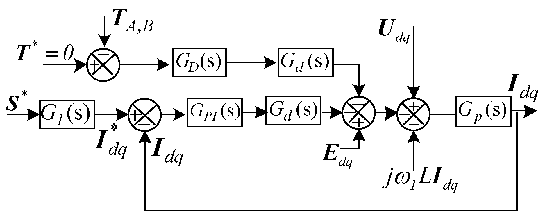
3.2. Fundamental Control Loop

The fundamental control loop is a vector control loop which is responsible for guaranteeing the output current can track the current reference precisely. The current reference can be derived by power reference as shown in Equation (8), in which S* is power reference, U * d q is the conjugate vector of grid voltage. The PI controller is employed in a fundamental control loop to track the fundamental current reference.
I d q * = S * 1 1.5 U * d q = S * 1 1.5 u d

3.3. Supplementary Control Loop

In the proposed supplementary control loop, TA,B is the control target, which can be alternative in A. Sinusoidal current, T = TA = Idq; B Steady power, T = TB = S, as can be written as Equation (9). T* is the reference of the control target and set as zero so that the supplementary control loop is aimed at eliminating current harmonics or power ripples.
{ T A = i d + j i q T B = P j Q
Reference of output voltage consists of the output of fundamental control loop, output of supplementary control loop and the decoupling component [21,22], thus the voltage reference of VSC can be described as:
V d q * = E d q U P I * U h *
The decoupling component Edq can be expressed as,
E d q = U d q 0 j ω g L I d q
The controller in the supplementary control loop is composed by the modified proportional-derivative controller with a high-pass filter (H-MPD). Since the bandwidth of the PI controller cannot cover the frequency of harmonics [4,5,6,7], the proportional-derivative controller was employed in a supplementary control loop to suppress the non-fundamental current or ripple power components. A prepositive high-pass filter was used to isolate the control of fundamental control loop and supplementary control loop. Meanwhile, in consideration of the differentiator having low practicability and introducing high frequency disturbances, a low-pass filter could be introduced to modify the proportional-derivative controller, which can be shown as:
G D ( s ) = K G h i g h p a s s ( s ) G m o d i f i e d P D ( s ) = K s 2 s 2 + 2 ε ω h s + ω h 2 ( 1 + 1 2 π f d s ) 1 1 + 1 2 π f l s
where, K represents the gain coefficient of the proposed H-MPD controller, GD(s) consists of two parts, Ghighpass(s) is a second order high-pass filter with damping ratio ε = 0.707. The cut-off frequency was set as 200 Hz, ωh = 2π200 Hz, considering the inter-harmonics higher than 200 Hz are comparatively serious [17,18,19,20], fd was the cut-off frequency of the proportional-derivative controller, which was set at 200 Hz also. fl was the cut-off frequency of the low-pass filter, which was set as 1 kHz, since the distortions at the frequency higher than 1 kHz were neglected in this paper.
The block diagram of VSC with the proposed strategy is shown in Figure 3. GPI(s) is the PI controller of fundamental control loop, GPI(s) = kp + ki/s, in which kp and ki represent the gain coefficient and integration coefficient. Gp(s) describes the mathematic model of the VSC, Gp(s) = 1/(R + sL), as shown in Figure 1. G1(s) is the transfer function from power to current, G1(s) = 1/1.5ud0. Gd(s) represents control delay, Gd(s) = e−1.5sT, in which T is the control period of VSC.
Figure 3 indicates that the output current and power is related with grid voltage Udq, power reference S* and supplementary control reference T*. Considering that T* is set at zero, the expressions of S and Idq can be written as,
{ I d q = H i u ( s ) U d q + H i s ( s ) S * S = H S u ( s ) U d q + H s s ( s ) S *
where, Hiu(s) and His(s) represent the transfer function from grid voltage and power reference to output current respectively, His(s) can be used to represent the track ability of the current loop, while Hiu(s) can be used to denote the harmonics current rejection ability of VSC. When GD(s) equals zero, Hiu(s) represents the harmonics current rejection ability of VSC without the proposed control strategy.
{ H i u ( s ) = G s ( s ) 1 + G d ( s ) G p ( s ) [ G D ( s ) + G P I ( s ) ] H i s ( s ) = G d ( s ) G p ( s ) G P I ( s ) G 1 ( s ) 1 + G d ( s ) G p ( s ) [ G D ( s ) + G P I ( s ) ]
Similarly, Hsu(s) and Hss(s) represent the transfer function from grid voltage and power reference to output power respectively. Hss(s) represents the track ability of power reference, while Hsu(s) represents the mitigation capacity of power ripples. Similarly, Hsu(s) represents the ripples mitigation capacity of VSC without the proposed control strategy when GD(s) equals to zero.
{ H s u ( s ) = G p ( s ) 1 + G d ( s ) G p ( s ) [ G D ( s ) + G P I ( s ) G 1 ( s ) ] H s s ( s ) = G d ( s ) G p ( s ) G P I ( s ) 1 + G d ( s ) G p ( s ) [ G D ( s ) + G P I ( s ) G 1 ( s ) ]
Therefore, Hiu(s), Hsu(s) can represent the adaptive ability of VSC to generalized distorted grid, which is reshaped by the proposed H-MPD controller GD(s) in the supplementary loop. In the next section, Hiu(s), Hsu(s) is analysed in detail to verify that the supplementary loop could decrease the magnitude of Hiu(s) and Hsu(s) significantly, which meant that the harmonics current rejection ability and power ripples mitigation capability were enhanced.

4. Performance Analyses of the Proposed Control Strategy

On the basis of the analysis in Section 3, for the sake of investigating the performance of the proposed strategy with different controller parameters, the analyses on Hiu(s) and Hsu(s) with different controller gain should be given to achieve the appropriate coefficient of the proposed H-MPD controller. Furthermore, the performance of fundamental control should be analysed to investigate the influence of the supplementary control loop.

4.1. Steady Performance of the Proposed Control Strategy

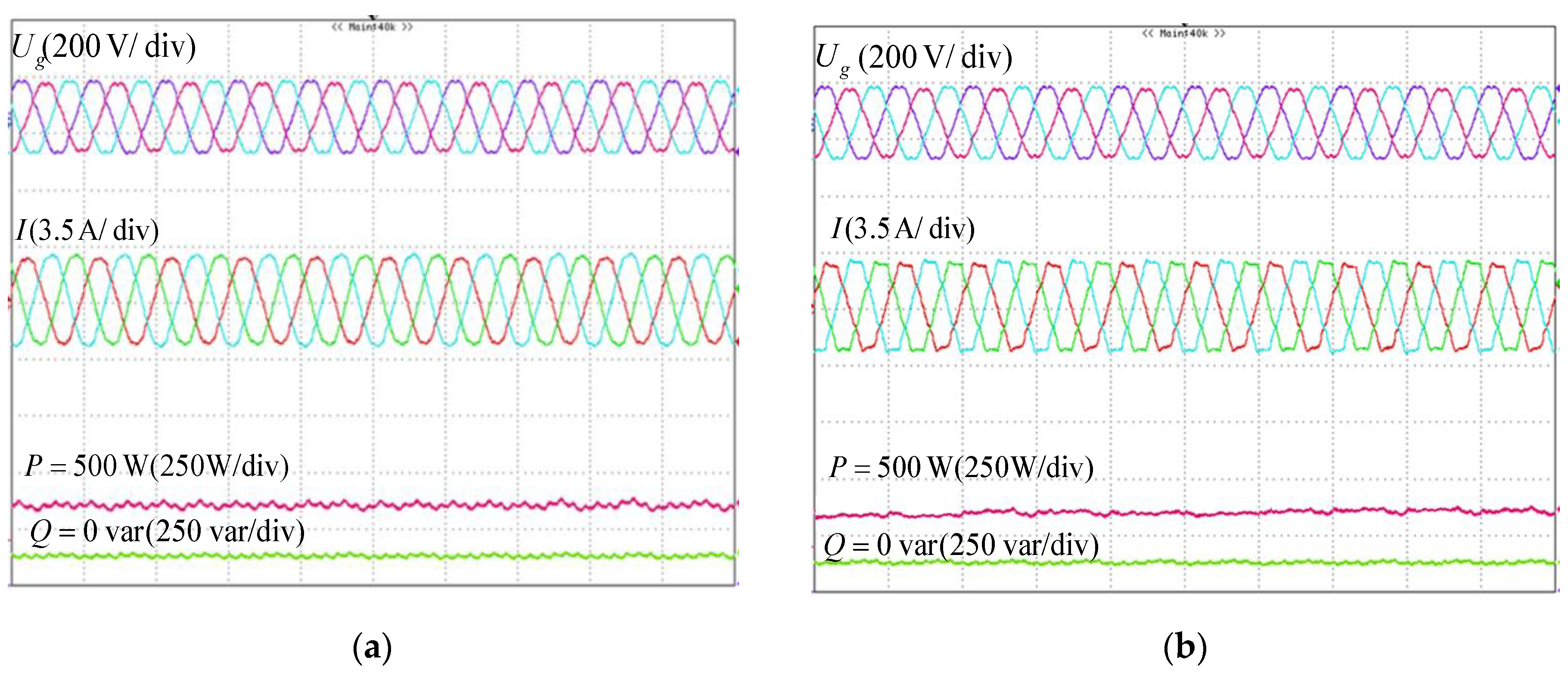
4.1.1. Target I, Sinusoidal Current

Bode diagrams of Hiu(s) with different K is given in Figure 4, which intended to illustrate the harmonics current rejection ability of VSC with or without the proposed control strategy. When K = 0, which means GD(s) = 0 and the proposed strategy was disabled, Hiu(s) are −4.9 dB −11 dB, at 300 Hz, 600 Hz, which was corresponding to the frequency of −5th, +7th components and 11th, 13th components respectively. The relatively large magnitude of Hiu(s) without the proposed controller in a frequency range from 200 Hz to 1000 Hz would result in the poor harmonic current suppression capability of VSC.
After introducing the proposed controller GD(s), the magnitude of Hiu(s) decreased to −26.4 dB −29.1 dB, at 300 Hz, 600 Hz with K = 8, which indicated that the proposed controller could decrease Hiu(s) significantly. It was found that the proposed strategy had the capability of suppressing current distortions effectively when the control target was set as the output current. Furthermore, with increasing K, the magnitude of Hiu(s) descended more, which indicated that the larger gain of the controller could bring the stronger capability for VSC to suppress the non-fundamental components of the output current.

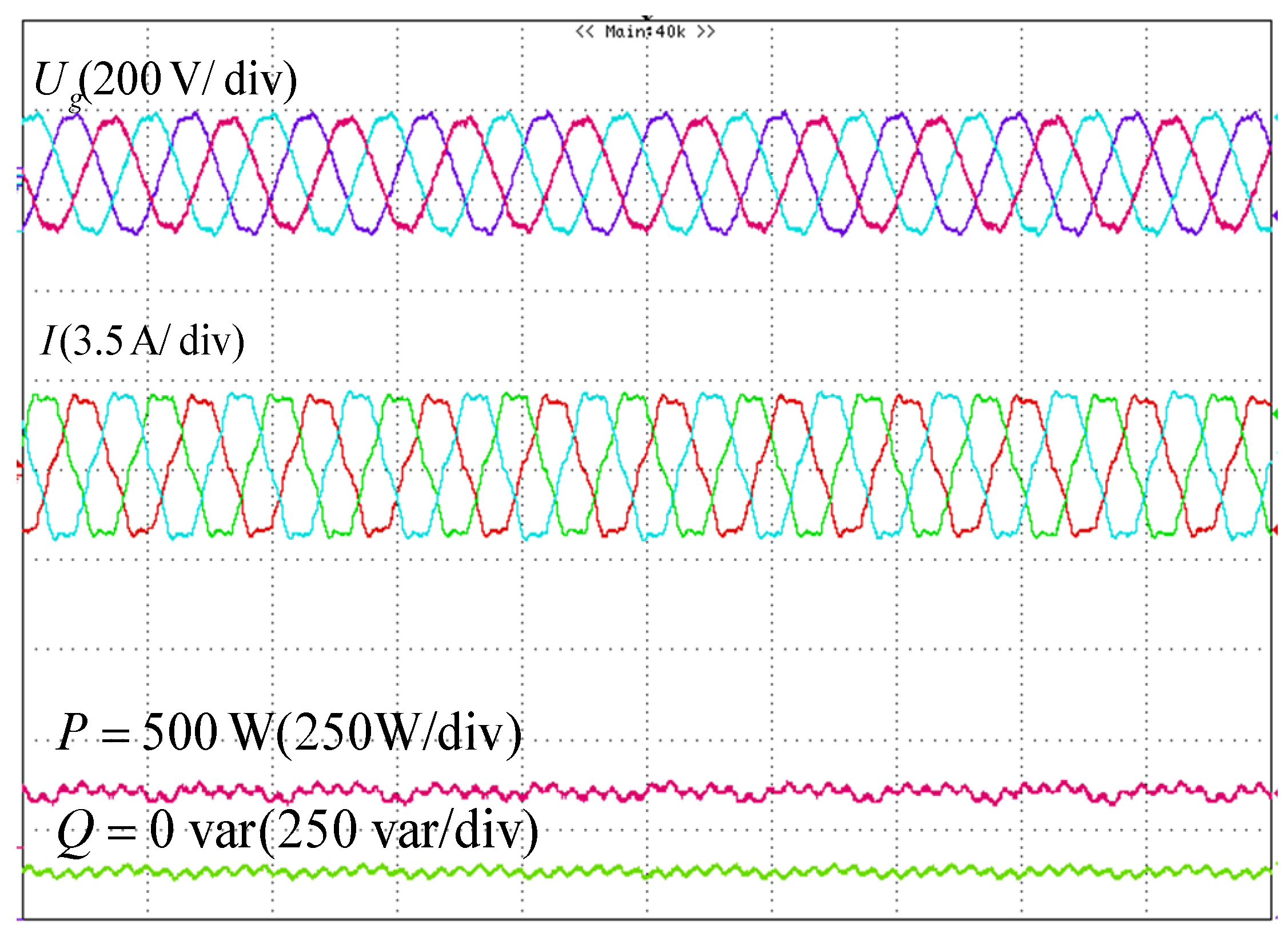
4.1.2. Target II, Steady Power without Ripples

Similarly, Hpu(s) can be used to analyze the control performance of VSC for the control target with smooth output power. Hpu(s) with different gain (K) is given in Figure 5, in which K = 0 means the proposed controller is not used, the magnitude of Hpu(s) was −16.9 dB and −21.0 dB at 300 Hz and 600 Hz, respectively. Additionally, the magnitude of Hpu(s) at the frequency range from 200 Hz to 1000 Hz was also large likewise, which meant that the VSC lacked the suppression ability of the power ripple with a fundamental control loop only.
As can be seen in Figure 5, when the controller was enabled, the magnitude of Hpu(s) decreased to −36.2 dB, −39.1 dB at 300 Hz, 600 Hz with K = 8, which indicated that the proposed controller could decrease Hiu(s) significantly. Also, the larger K brought a lower magnitude for Hpu(s). Therefore, the proposed controller had the ability to reshape Hpu(s) and improving the capacity of mitigating power ripples for VSC. Additionally, the larger control gain meant that the proposed strategy of this paper could suppress power ripples with a stronger capability.

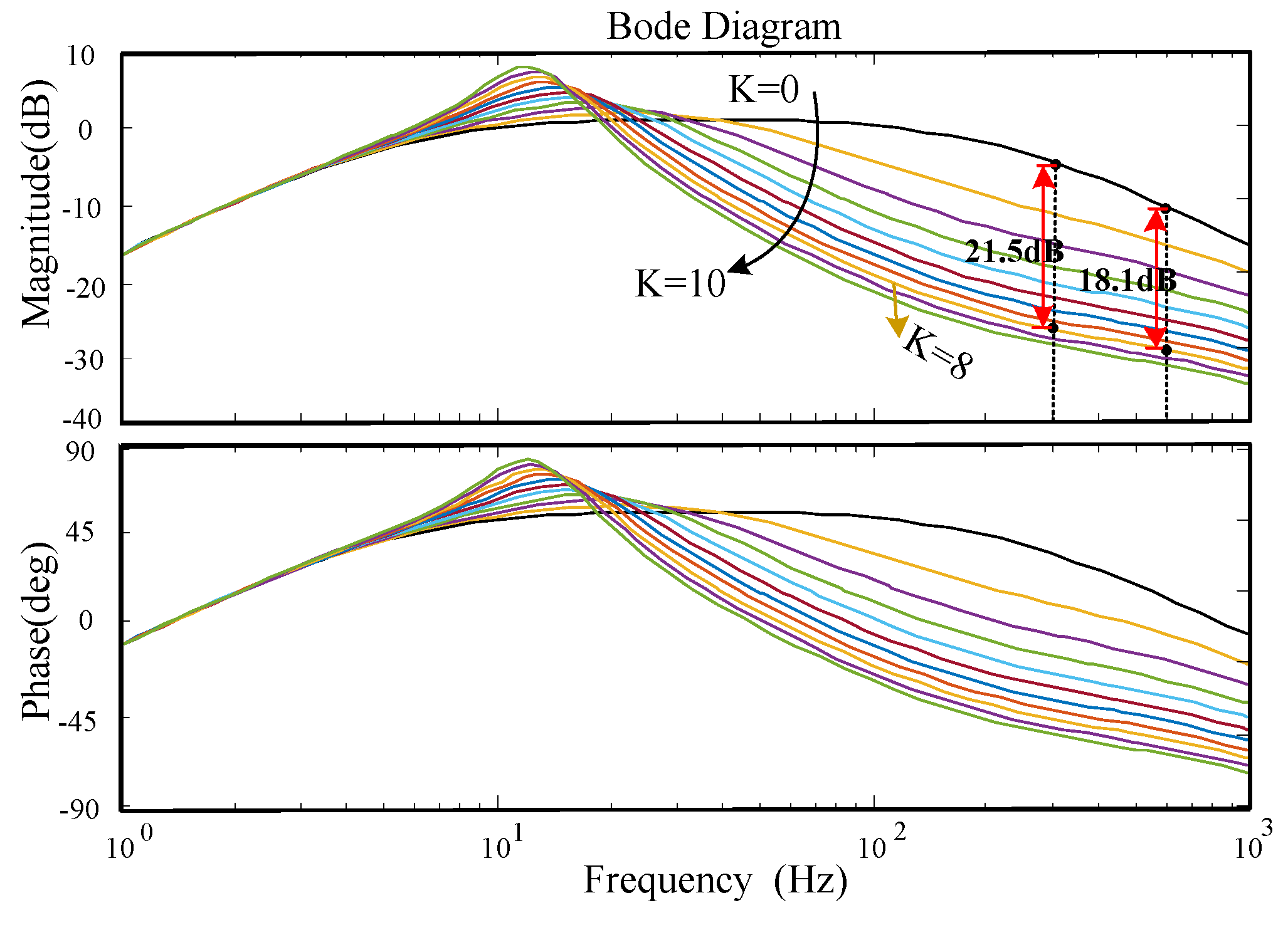
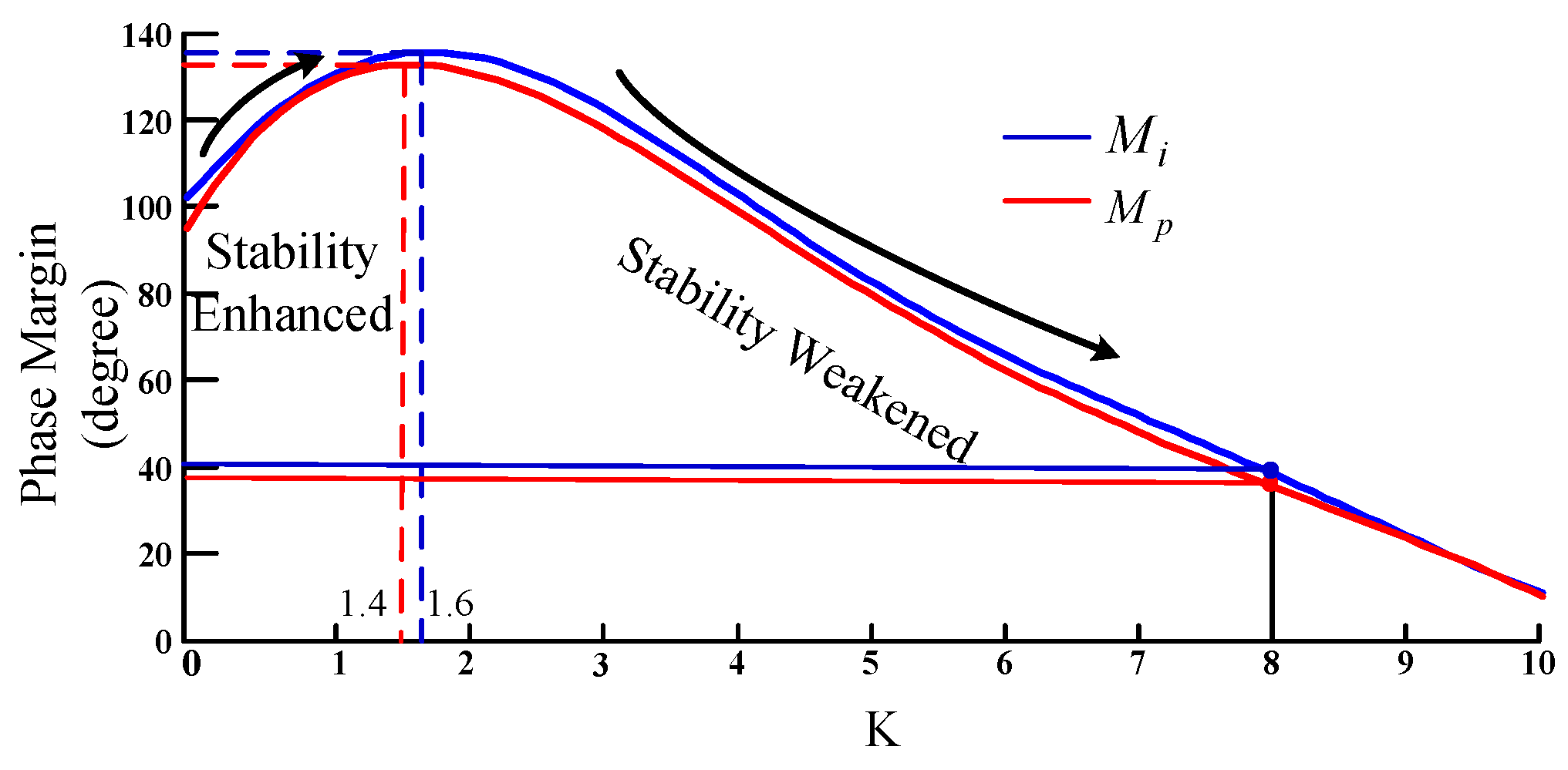
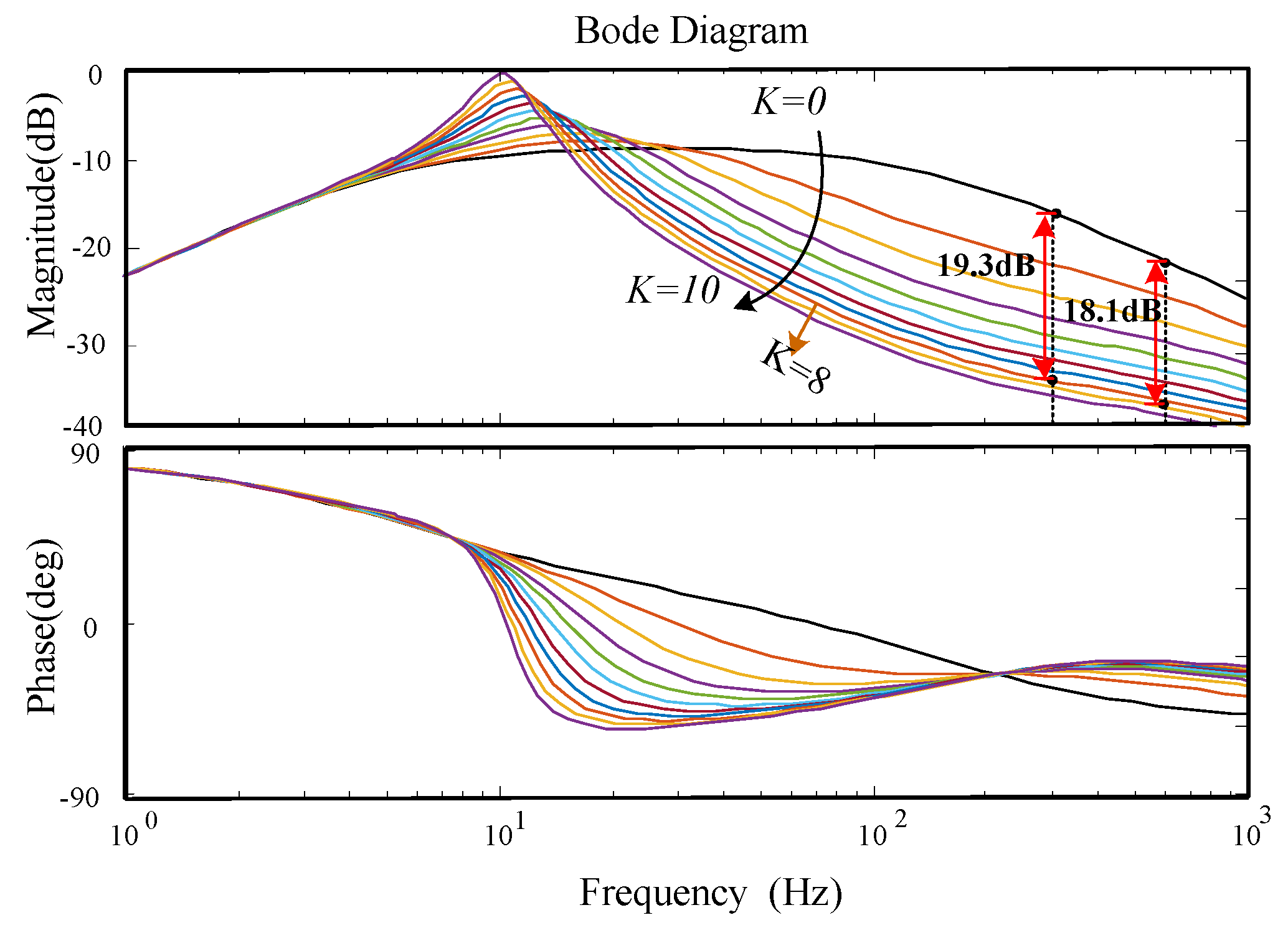
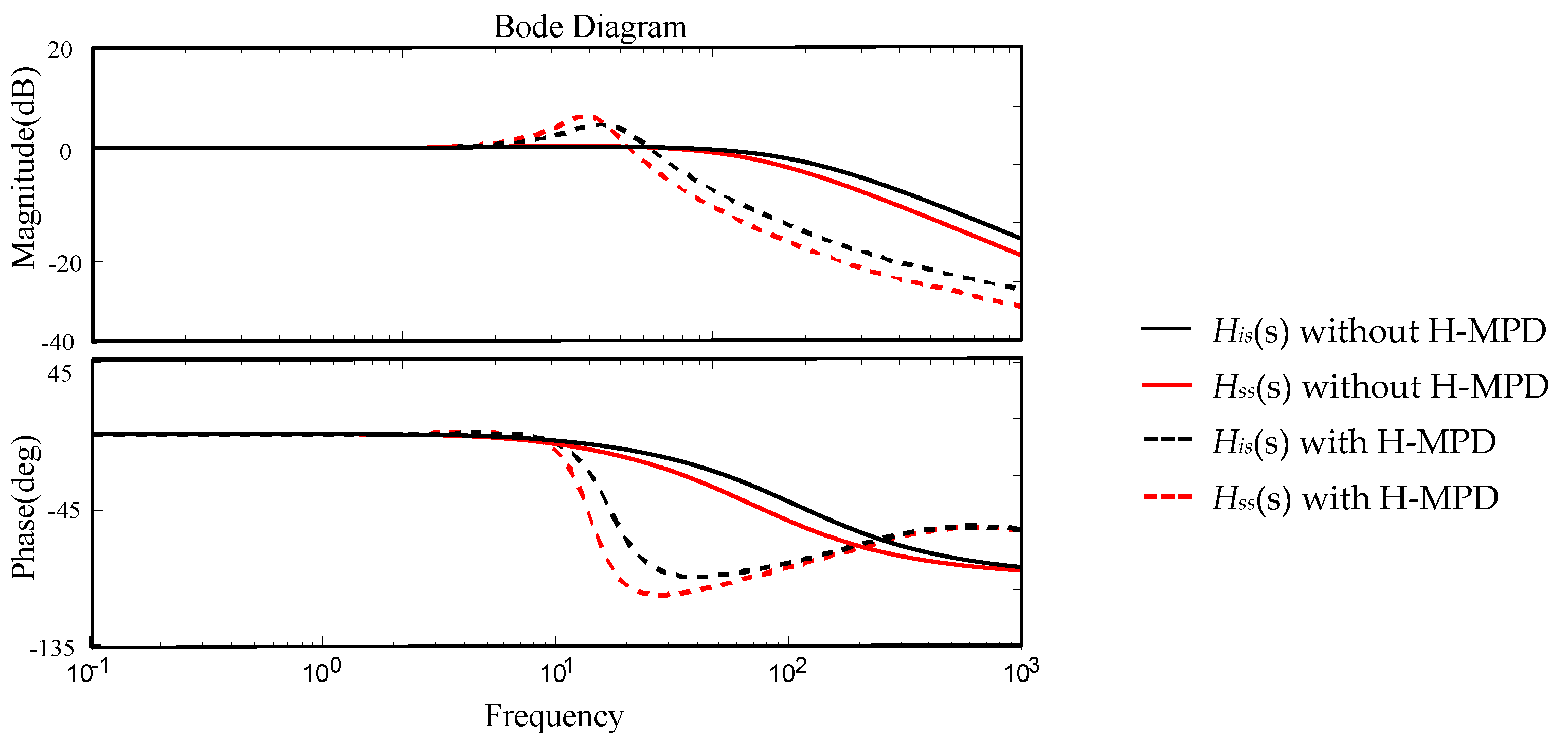
4.2. Stability Analyses for VSC

The transfer function of an open loop can be employed to reflect the stability of a close loop system, thus the stability analyses based on the transfer function of open loop has been investigated in this section. According to Equations (14) and (15), the open loop transfer function of VSC can be expressed as:
{ M i = G d ( s ) G p ( s ) [ G D ( s ) + G P I ( s ) ] M p = G d ( s ) G p ( s ) [ G D ( s ) + G P I ( s ) G 1 ( s ) ]
where, Mi(s) represents the open loop transfer function of VSC with the supplementary control target as the output current, while Mp(s) corresponds to the condition that the control target is set as the output power.
Figure 6 shows the phase margin of VSC with different values of gain coefficient (K), where the blue line represents Mi and red line represents Mp. As demonstrated in Figure 6, the proposed control strategy with different control targets had a similar influence on system stability, the introduction of GD enhanced the stability of the system when K was lower than 1.4 (Mp) and 1.6 (Mi). However, if K increased further, the stability of system weakened gradually. Therefore, for the proposed controller, there was a trade-off that the larger controller gain could bring a better control performance, while the stability of the system would be weakened.
Based on the analyses of the steady performance and the stability, the controller gain K was set as 8 in this paper. In the case of K = 8, Hiu(s) decreased to −26.4 dB, −29.1 dB at 300 Hz and 600 Hz. On the condition of the setting output current as the control target. Hpu(s) decreased to −36.2 dB, −39.1 dB at 300 Hz and 600 Hz, when the control target was output power. As shown in Figure 5 and Figure 6, before and after employing the proposed controller, the magnitude of Hiu(s) and Hpu(s) could be decreased to more than 18 dB and 16 dB, respectively in the frequency between 200 Hz to 1000 Hz. In brief, the proposed control strategy had a good steady control performance for improving the output current quality or mitigating power ripples. In addition, when K = 8, the phase margin of Mi(s) and Mp(s) were 40.3° and 38.8°, which indicated that the VSC system with the proposed controller still had enough stability capability.

4.3. Performance Analyses of Fundamental Control

In order to avoid the negative influence on the fundamental control loop, which was introduced by the supplementary loop, a prepositive high-pass filter was employed in GD(s). In view of His(s) and Hss(s), which represented the response of the current and power to the power reference respectively, thus the effect of fundamental control after introducing the proposed controller was investigated here.
Bode diagrams of His(s) and Hss(s) with and without the proposed control strategy is given in Figure 7. As exhibited in Figure 7, the magnitude and phase of His(s) and Hss(s) without the proposed control were both 0 dB and 0° when the frequency reached zero, which meant that the fundamental control loop had the capacity of tracking the reference without errors. After employing the proposed control strategy, His(s) and Hss(s) was kept fixed when the frequency tended toward zero, which meant that the power reference and current reference could be tracked without errors.
What can be concluded is that the strategy of this paper not only could suppress the harmonic current or power ripples, but would also not affect the steady-state performance of fundamental control.

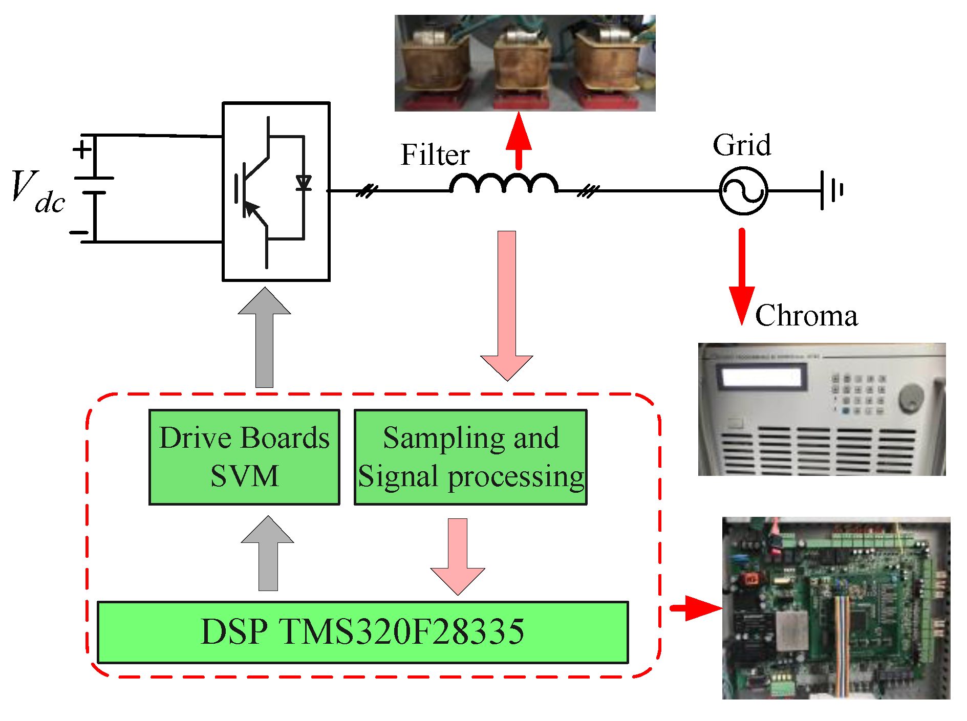
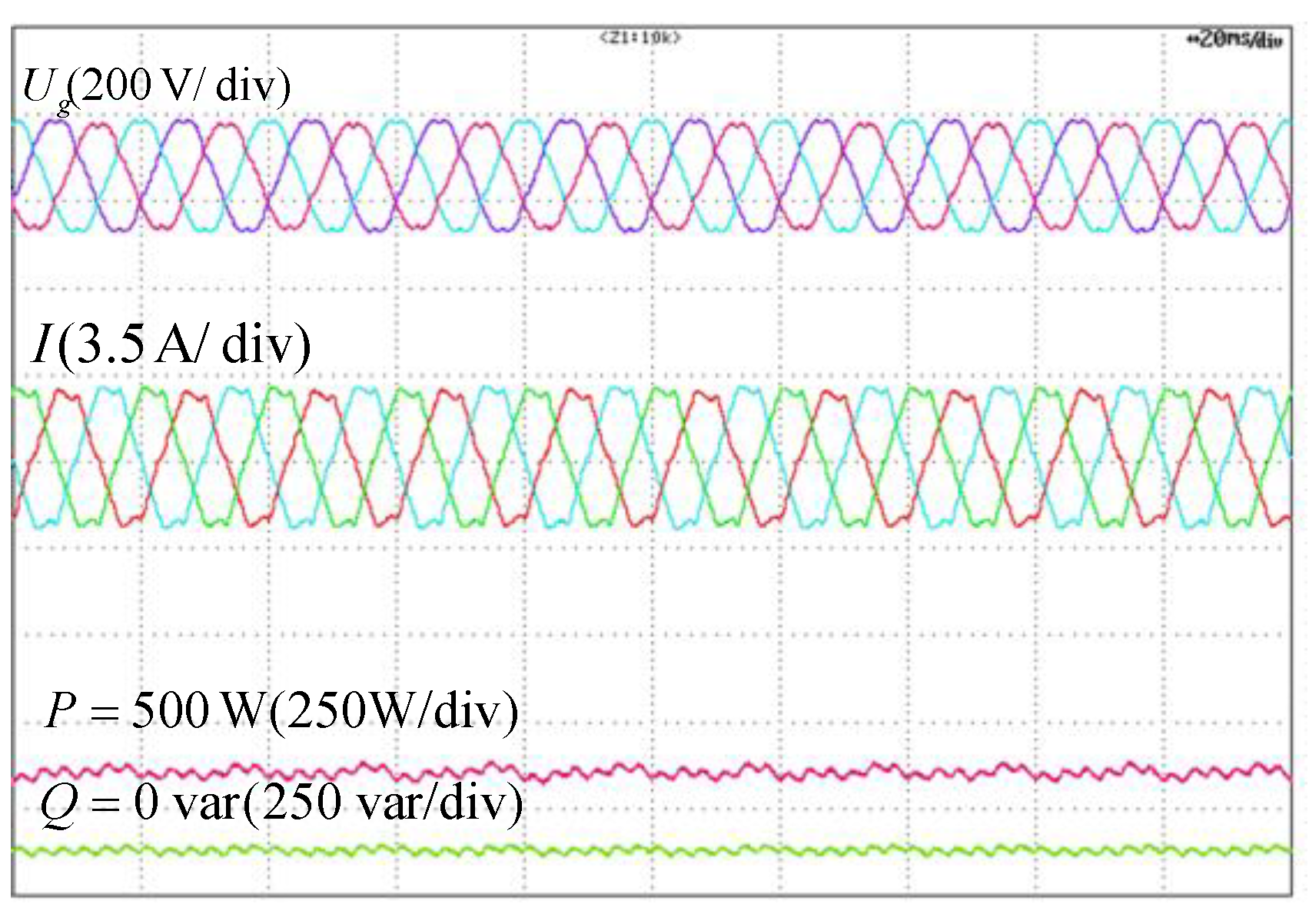
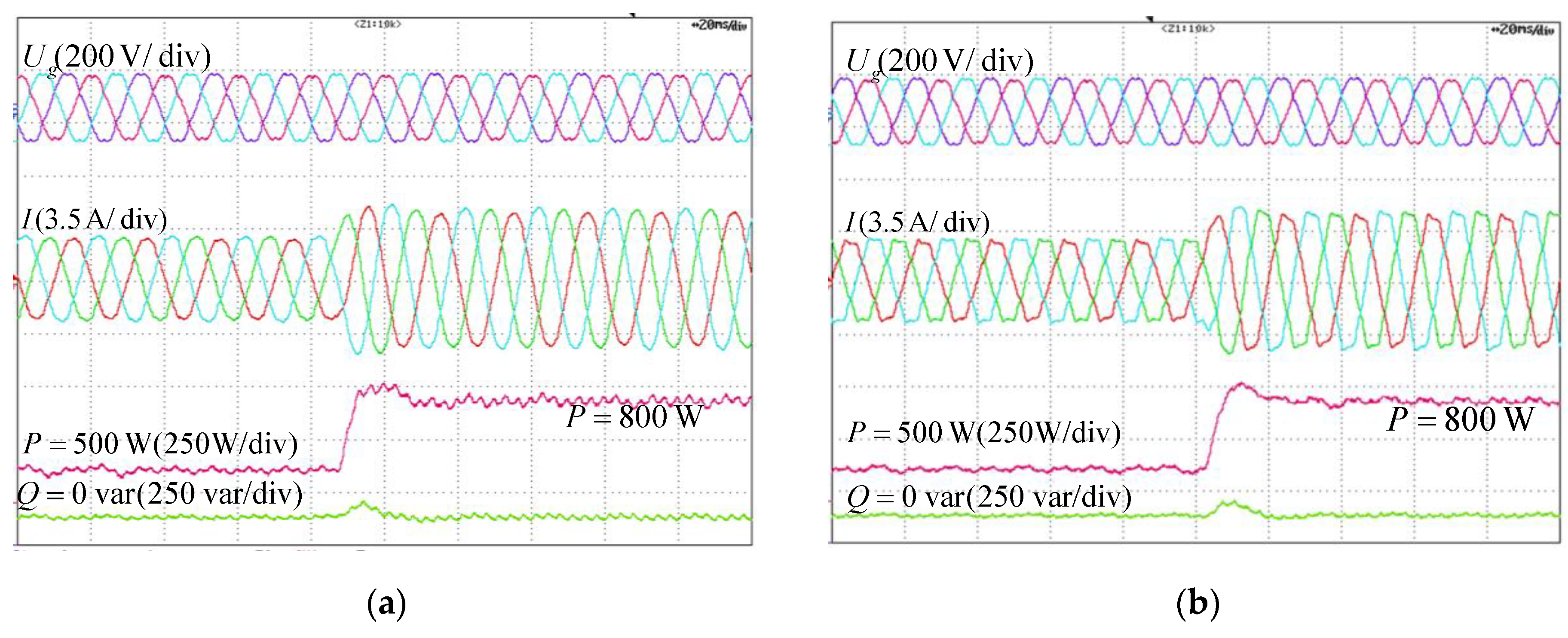
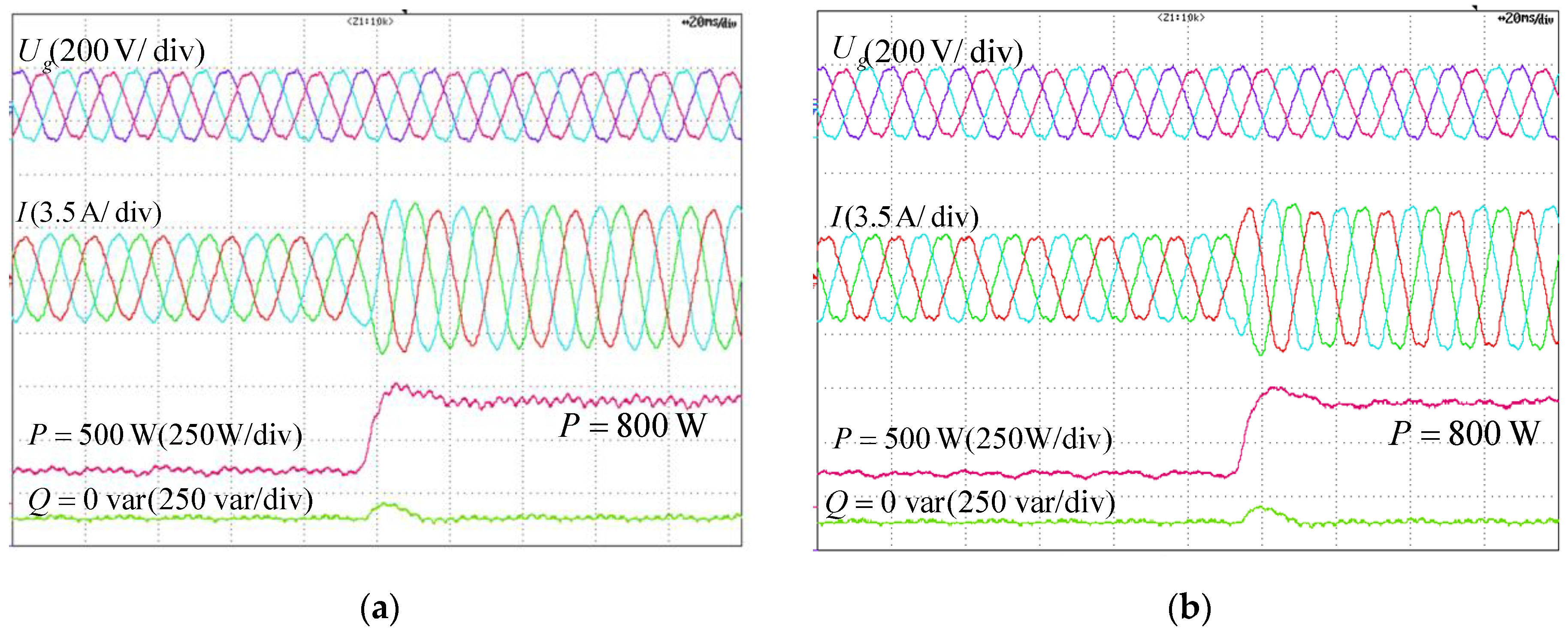
5. Experimental Verification

For the sake of verifying the validity of the proposed strategy in this paper, the experiments were carried out on a VSC system, whose structure can be seen in Figure 8. DC bus is supplied by a DC source, and the AC side of VSC connects the grid via a filter inductance, in which the grid is emulated by the programmable source. The rated power of the experimental system was 500 W, rated AC voltage and DC voltage were 110 V and 250 V, line resistors and inductors were 0.001 Ω and 6 mH and sampling frequency was 10 kHz.
Figure 9 gives the operation performance of VSC without the proposed control strategy under the integer harmonic grid, in which grid voltage consisted of 5th, 7th, 11th, 13th components, which were 3.51%, 2.53%, 1.50%, 1.20% respectively. The reference of output active and reactive power was 500 W and 0 var. As can be seen in Figure 9, the non-sinusoidal output current and power ripples exist, in which the 5th, 7th, 11th, 13th components in output current were 5.99%, 4.36%, 1.24%, 0.78% respectively, while the active power ripple was 19.5 W and the reactive power ripple was 16.8 var.
Figure 10 displays the operation of VSC with the proposed control strategy under a integer harmonic grid. When the control target of the proposed control strategy was set as sinusoidal current, the non-fundamental components in the output current was suppressed, in which the 5th, 7th, 11th, 13th components in output current decreased to 1.25%, 1.11%, 0.42%, 0.40%, respectively and the output power quality improved significantly. As to the power ripples on these conditions, the active power ripple was 14.3 W and the reactive power ripple was 12.6 var.
Figure 10b shows the operation of VSC with the control target as the steady output power, the ripples in active and reactive power were mitigated to 5.7 W and 5.2 var, respectively. However, on this condition, the 5th, 7th, 11th, 13th components in the output current were 4.25%, 4.14%, 2.61%, and 1.20%, respectively.
Figure 11 gives the power regulation of VSC with the strategy of this paper. When the power reference changed from 500 W to 800 W, the output power of VSC could be regulated precisely. The experimental results in Figure 11 revealed that the strategy of this paper could improve the adaptive capability of VSC for the integer harmonics, while the fundamental control performance would not be worsened. No matter what the control target is set as, whether it is sinusoidal current or smooth power, the power can be regulated accurately.
It should be pointed out that the control targets of the sinusoidal current and steady power were simultaneously contradictory and the achievement of one control target would deteriorate another control target.
For validating the availability of the strategy for inter-harmonics, Figure 12 gives the operation of VSC without the proposed control strategy, when grid voltage contains inter-harmonics. In Figure 12, grid voltage consisted of 288 Hz, 336 Hz, 528 Hz components, which were 3.36%, 3.89%, 1.35%, respectively while the reference of output active power and reactive power was 500 W and 0 var, respectively. When the proposed controller was disabled, the inter-harmonics with 288 Hz, 336 Hz and 528 Hz existed in the output current. The components of the inter-harmonics were 5.61%, 4.24% and 1.46%, respectively, while the ripples in the output power were 21.4 W and 17.5 var.
Figure 13 gives the operation of VSC after enabling the proposed control strategy. When the proposed controller aimed at suppressing the current distortions, the sinusoidal current could be obtained, as shown in Figure 13a, the 288 Hz, 336 Hz and 528 Hz components in output current were decreased to 1.26%, 1.11%, 0.39% respectively, the output power ripples in this case were 16.2 W and 10.1 var. As to the goal of mitigating power ripples, Figure 13b verified the effectiveness of the strategy in this paper, in which the ripples in active power and reactive power were suppressed to 6.2 W and 6.6 var, while the 288 Hz, 336 Hz and 528Hz components in output current were 3.16%, 3.31%, 1.39% respectively.
For investigating the influence on the power tracking caused by the proposed strategy. Figure 14 shows the power regulation of VSC under an integer harmonics grid after enabling the proposed strategy. When the power reference changed from 500 W to 800 W, the output power of VSC could be regulated precisely on the condition of the inter-harmonics grid, the power regulation of VSC system operated well, regardless the control target that was selected as sinusoidal current or smooth power.
Table 1 illustrates the contrastive analysis of the experimental results, the analysis in Table 1 indicates that the proposed control strategy could implement the control targets of sinusoidal current and steady power alternatively. Meanwhile the strategy was effective on the conditions of the distorted grid, which included integer harmonics and inter-harmonics.
According to the experimental results and the analysis, what can be concluded is that the proposed control strategy can improve the power quality or mitigate the power ripples effectively according to the different control target, under the grid distortions with considering integer and inter-harmonics. Additionally, the theoretical analysis and the experiments confirm that the proposed strategy of this paper will not deteriorate the fundamental power control, while enhancing the adaptive ability of VSC for the generalized grid harmonics.

6. Conclusions

This paper proposed the suppressing method on the distorted currents and power ripples of VSC alternatively under grid harmonics with the consideration of integer and inter-harmonics. The conclusions and contributions of this paper can be highlighted as follows:
(1) The supplementary control loop based on the H-MPD controller can work effectively within a wide frequency range, thereby the inter-harmonic current or power ripples caused by inter-harmonics can be suppressed without detecting inter-harmonics frequency.
(2) The control target can be alternative in sinusoidal current or steady output power to satisfy the different grid-connected operation requirements.
(3) The proposed control strategy will not deteriorate the fundamental control performance, which is beneficial for the maximum power track operation of renewable power generation system.

Author Contributions

Data curation, B.P. and H.N.; Formal analysis, B.P.; Investigation, B.P. and H.N.; Methodology, B.P. and H.N.; Project administration, H.N.; Software, B.P.; Supervision, H.N.; Validation, B.P.; Writing-original draft, B.P.; Writing-review & editing, H.N.

Funding

This work is supported in part by the National Natural Science Foundation of China under Grant 51622706, in part by the Fundamental Research Funds for the Central Universities under Grant 2017XZZX002-17.

Conflicts of Interest

The authors declare no conflict of interest.

References

  1. Blaabjerg, F.; Teodorescu, R.; Liserre, M.; Timbus, A.V. Overview of control and grid synchronization for distributed power generation systems. IEEE Trans. Ind. Electron. 2006, 53, 1398–1409. [Google Scholar] [CrossRef]
  2. Xie, H.; Bie, Z.; Lin, Y.; Zheng, C. A hybrid reliability evaluation method for meshed VSC-HVDC grids. Energies 2017, 10, 895. [Google Scholar] [CrossRef]
  3. Hwang, J.G.; Lehn, P.W.; Winkelnkemper, M. A generalized class of stationary frame-current controllers for grid-connected AC-DC converters. IEEE Trans. Power Delivery 2010, 25, 2742–2751. [Google Scholar] [CrossRef]
  4. Hu, J.; Zhu, Z.Q. Investigation on switching patterns of direct power control strategies for grid-connected DC-AC converters based on power variation rates. IEEE Trans. Power Electron. 2011, 26, 3582–3598. [Google Scholar] [CrossRef]
  5. Song, Y.; Nian, H. Sinusoidal Output Current Implementation of DFIG Using Repetitive Control Under a Generalized Harmonic Power Grid with Frequency Deviation. IEEE Trans. Power Electron. 2015, 30, 6751–6762. [Google Scholar] [CrossRef]
  6. The National Standard of the People’s Republic of China (GB/T 14549-93). Quality of Electric Energy Supply—Harmonics in Public Supply Network; General Administration of Quality Supervision, Inspection and Quarantine of the People’s Republic of China: Beijing, China, 1994.
  7. IEEE Std 519-2014 (Revision of IEEE Std 519-1992)—Redline. IEEE Recommended Practice and Requirements for Harmonic Control in Electric Power Systems—Redline; IEEE: Piscataway, NJ, USA, 2014. [Google Scholar]
  8. Tran, T.V.; Yoon, S.J.; Kim, K.H. An LQR-based controller design for an LCL-filtered grid-connected inverter in discrete-time state-space under distorted grid environment. Energies 2018, 11, 2062. [Google Scholar] [CrossRef]
  9. Nian, H.; Shen, Y.; Yang, H.; Quan, Y. Flexible Grid Connection Technique of Voltage-Source Inverter Under Unbalanced Grid Conditions Based on Direct Power Control. IEEE Trans. Ind Appl. 2015, 51, 4041–4050. [Google Scholar] [CrossRef]
  10. Rodrigues, P.; Timbus, A.V.; Teodorescu, R.; Liserre, M.; Blaabjerg, F. Flexible active power control of distributed power generation systems during grid faults. IEEE Trans. Ind. Electron. 2007, 54, 2583–2592. [Google Scholar] [CrossRef]
  11. Li, L.; Nian, H.; Cheng, P. Direct power control for voltage source inverter without phase-locked loop under harmonically distorted voltage conditions. In Proceedings of the 19th International Conference on Electrical Machines and Systems (ICEMS), Chiba, Japan, 13–16 November 2016; pp. 1–6. [Google Scholar]
  12. Teodorescu, R.; Liserre, M.; Rodrigues, P. Grid Converters for Photovoltaic and Wind Power Systems; John Wiley & Sons: Hoboken, NJ, USA, 2011. [Google Scholar]
  13. Liserre, M.; Teodorescu, R.; Blaabjerg, F. Multiple harmonics control for three-phase grid converter systems with the use of PI-RES current controller in a rotating frame. IEEE Trans. Power Electron. 2006, 21, 836–841. [Google Scholar] [CrossRef]
  14. Jin, T.; Wei, H.; Nzongo, D.L.M.; Zhang, Y. Model predictive control strategy for NPC grid-connected inverters in unbalanced grids. Electron. Lett. 2016, 52, 1248–1250. [Google Scholar] [CrossRef]
  15. Cheng, C.; Nian, H. Low-Complexity Model Predictive Stator Current Control of DFIG Under Harmonic Grid Voltages. IEEE Trans. Energy Convers. 2017, 32, 1072–1080. [Google Scholar] [CrossRef]
  16. Rajapakse, G.; Jayasinghe, S.; Fleming, A.; Negnevitsky, M. Grid Integration and Power Smoothing of an Oscillating Water Column Wave Energy Converter. Energies 2018, 11, 1871. [Google Scholar] [CrossRef]
  17. Kang, S.; Kim, K. Sliding mode harmonic compensation strategy for power quality improvement of a grid-connected inverter under distorted grid condition. IET Power Electron. 2015, 8, 1461–1472. [Google Scholar] [CrossRef]
  18. Testa, A.; Akram, M.F.; Burch, R.; Carpinelli, G.; Chang, G.; Dinavahi, V.; Hatziadoniu, C.; Grady, W.M.; Gunther, E.; Halpin, M.; Lehn, P. Inter-harmonics: Theory and Modeling. IEEE Trans. Power Delivery 2007, 22, 2335–2348. [Google Scholar] [CrossRef]
  19. Lin, H.C. Inter-Harmonic Identification Using Group-Harmonic Weighting Approach Based on the FFT. IEEE Trans. Power Electron. 2008, 23, 1309–1319. [Google Scholar]
  20. Gunther, E.W. Interharmonics-recommended updates to IEEE 519. In Proceedings of the IEEE Power Engineering Society Summer Meeting, Chicago, IL, USA, 21–25 July 2002; pp. 950–954. [Google Scholar]
  21. Guillen-Garcia, E.; Zorita-Lamadrid, A.L.; Duque-Perez, O.; Morales-Velazquez, L.; Osornio-Rios, R.A.; Romero-Troncoso, R.J. Power Consumption Analysis of Electrical Installations at Healthcare Facility. Energies 2017, 10, 64. [Google Scholar] [CrossRef]
  22. Pang, B.; Nian, H.; Xu, G.; Qiu, J. Method of eliminating high frequency resonance of DFIG system connected to weak grid. J. Eng. 2017, 13, 1793–1798. [Google Scholar] [CrossRef]
  23. Nian, H.; Pang, B. Stability and Power Quality Enhancement Strategy for DFIG System Connected to Harmonic Grid with Parallel Compensation. IEEE Trans. Energy Convers. 2018, 1, 1. [Google Scholar]
  24. Rahmann, C.; Castillo, A. Fast frequency response capability of photovoltaic power plants: The necessity of new grid requirements and definitions. Energies 2014, 7, 6306–6322. [Google Scholar] [CrossRef]
Figure 1. The circuit diagram of voltage source converter (VSC).
Energies 12 01236 g001
Figure 2. The proposed control strategy with flexible control targets.
Energies 12 01236 g002
Figure 3. Block diagram of VSC with the proposed control.
Energies 12 01236 g003
Figure 4. Bode diagrams of Hiu(s) with different K.
Energies 12 01236 g004
Figure 5. Bode diagrams of Hpu(s) with different K.
Energies 12 01236 g005
Figure 6. Phase margin of VSC when the proposed controller with different K.
Energies 12 01236 g006
Figure 7. Phase margin of VSC when the proposed controller was used with different K.
Energies 12 01236 g007
Figure 8. Schematic diagram of the experimental system.
Energies 12 01236 g008
Figure 9. Experiments of VSC under a integer harmonics grid without the proposed control.
Energies 12 01236 g009
Figure 10. Experimental results of VSC under integer harmonics grid with the proposed control. (a) Target I sinusoidal current; (b) Target II, steady power without ripples.
Energies 12 01236 g010
Figure 11. Power regulation of VSC under integer harmonics grid with the proposed control. (a) Power regulation with the target I; (b) Power regulation with the target II.
Energies 12 01236 g011
Figure 12. Operation of VSC under a inter- harmonics grid without the proposed control.
Energies 12 01236 g012
Figure 13. Operation of VSC under inter-harmonics grid with the proposed control. (a) Target I sinusoidal current; (b) Target II, steady power without ripples.
Energies 12 01236 g013
Figure 14. Power regulation of VSC under integer harmonics grid with the proposed control strategy. (a) Power regulation with the target I; (b) Power regulation with the target II.
Energies 12 01236 g014
Table 1. Contrastive analysis of the experimental results.
DistortionTargetTHD of IRipples of PRipples of Q
Integer HarmonicsNone7.55%19.5 W16.8 Var
TA1.82%14.3 W12.6 Var
TB6.59%5.7 W5.2 Var
Inter-HarmonicsNone7.18%21.4 W17.5 Var
TA1.77%16.2 W10.1 Var
TB4.88%6.2 W6.6 Var

