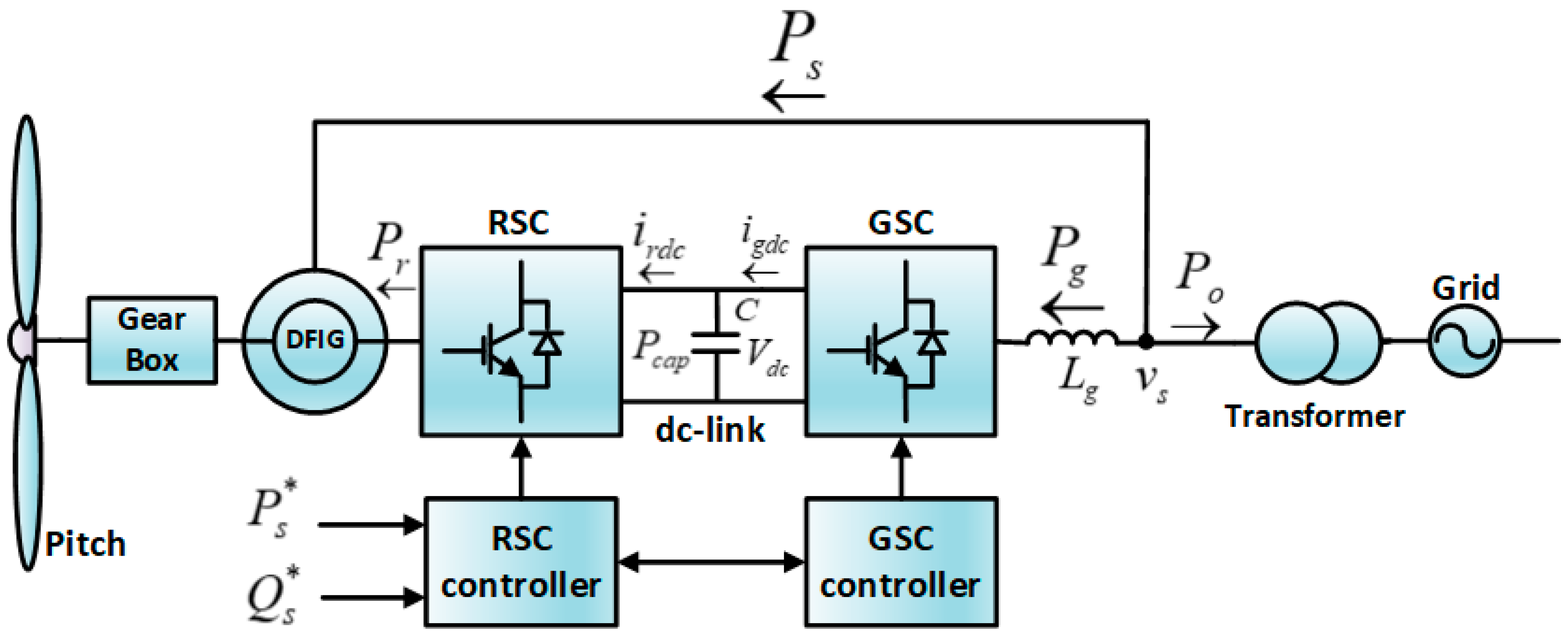
Figure 1.
Active power flow in a DFIG wind turbine.
Figure 1.
Active power flow in a DFIG wind turbine.
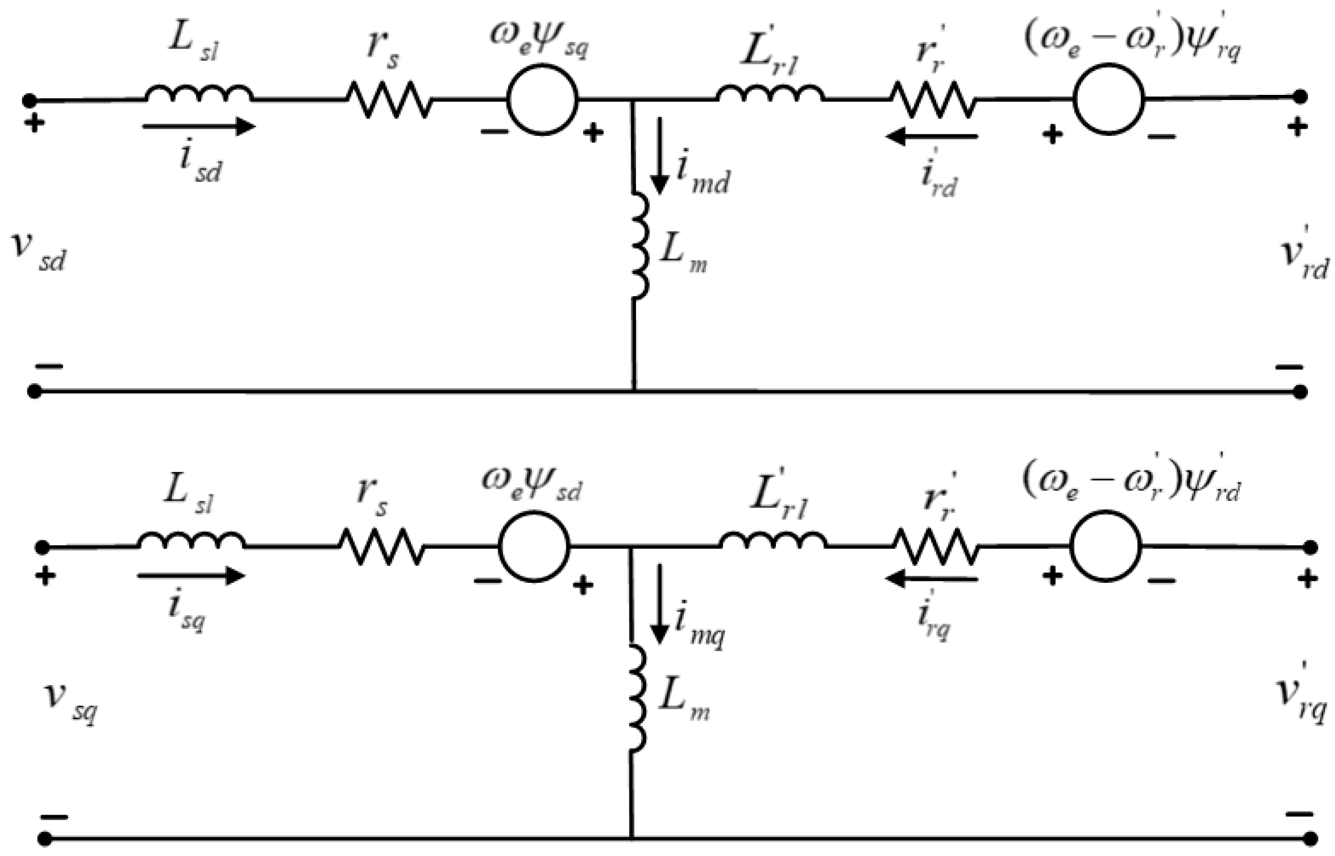
Figure 2.
Equivalent circuit of the DFIG in the dq-synchronous reference frame.
Figure 2.
Equivalent circuit of the DFIG in the dq-synchronous reference frame.
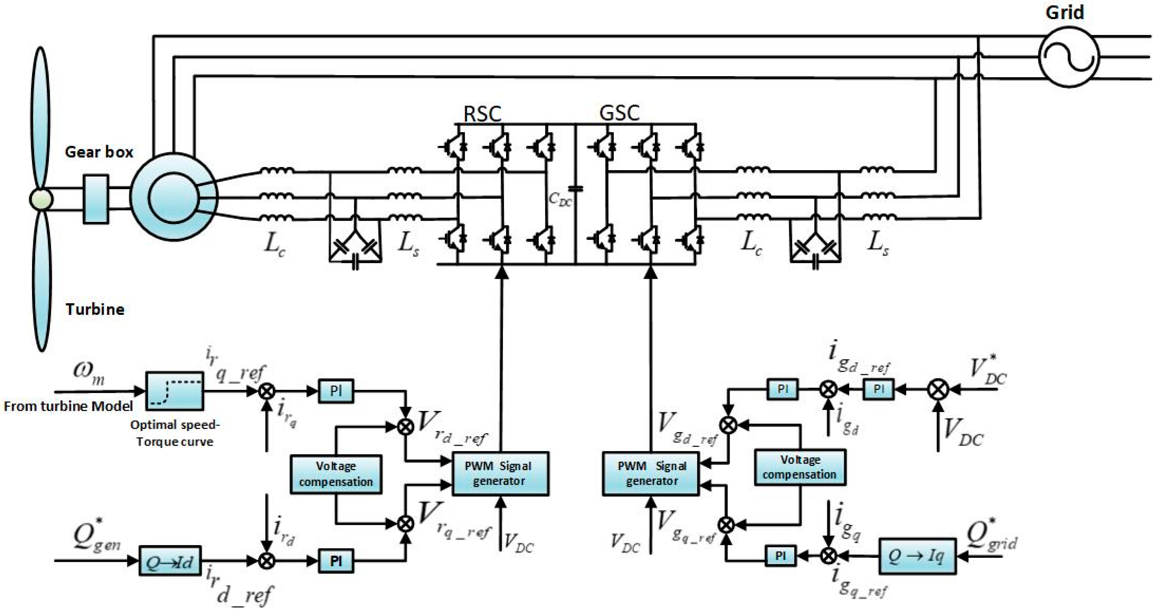
Figure 3.
Control schematics for a DFIG wind turbine.
Figure 3.
Control schematics for a DFIG wind turbine.
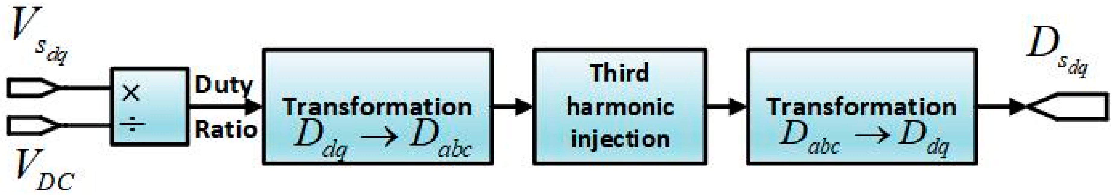
Figure 4.
Modulation of generator-side converter in proposed model.
Figure 4.
Modulation of generator-side converter in proposed model.
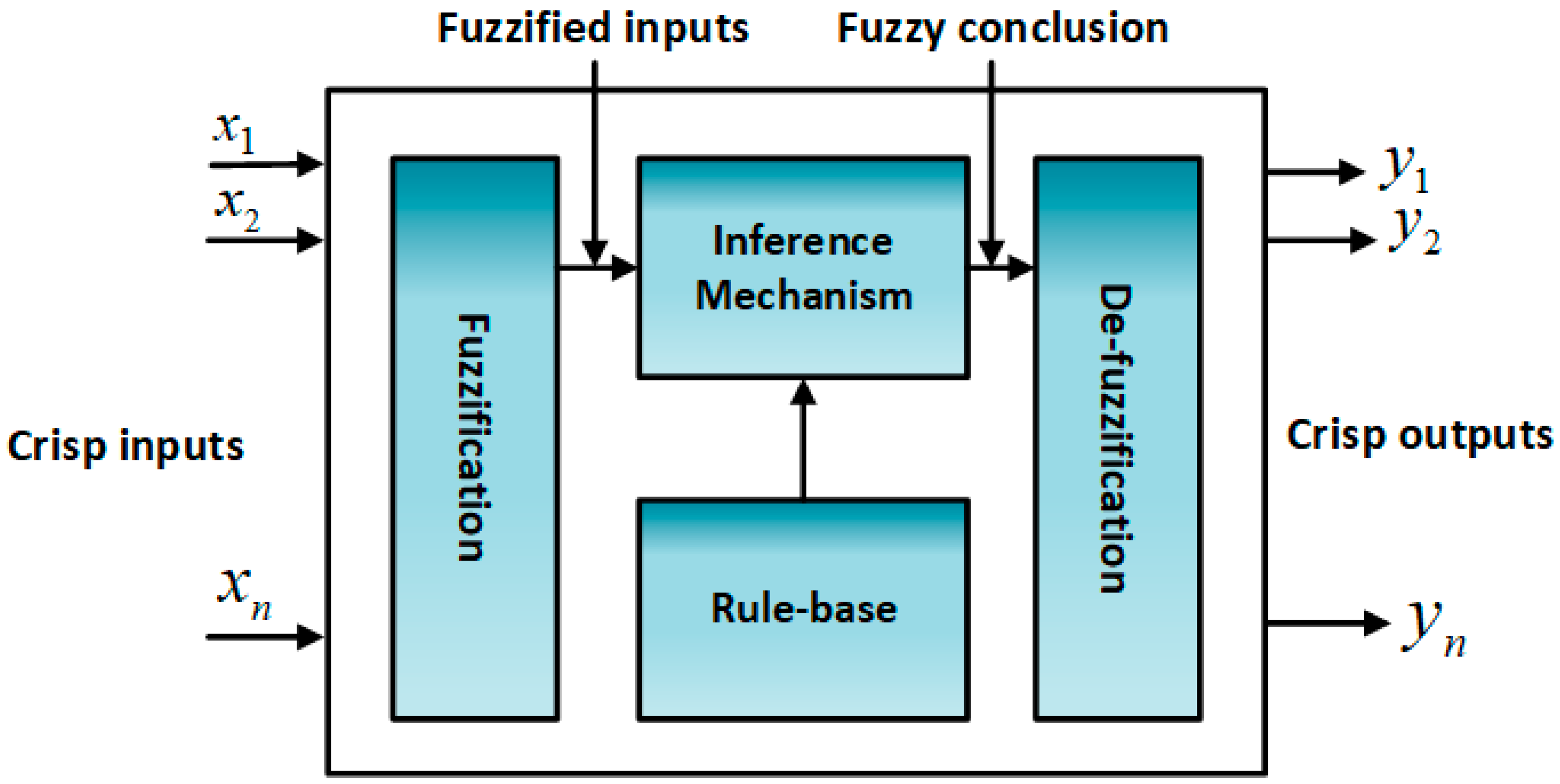
Figure 5.
Fuzzy controller architecture.
Figure 5.
Fuzzy controller architecture.
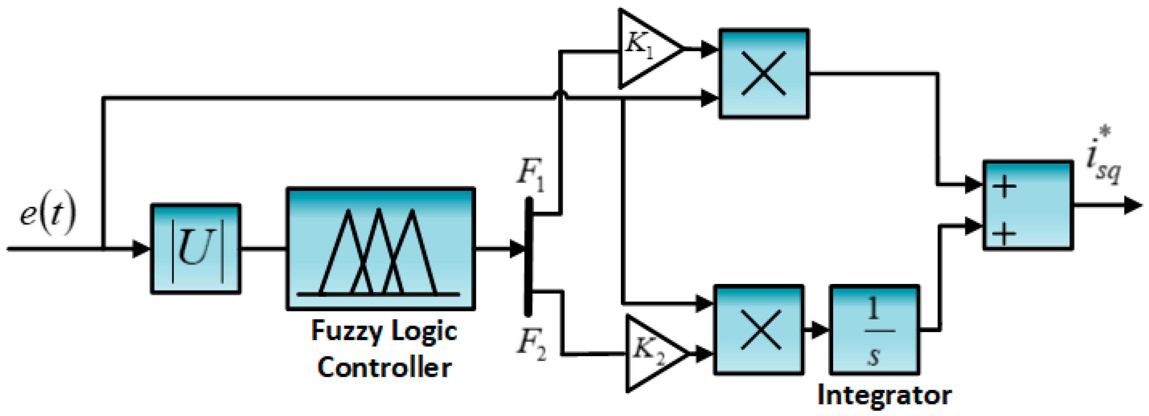
Figure 6.
Adaptive PI controller.
Figure 6.
Adaptive PI controller.
Figure 7.
Combined structure of PR with harmonic compensator.
Figure 7.
Combined structure of PR with harmonic compensator.
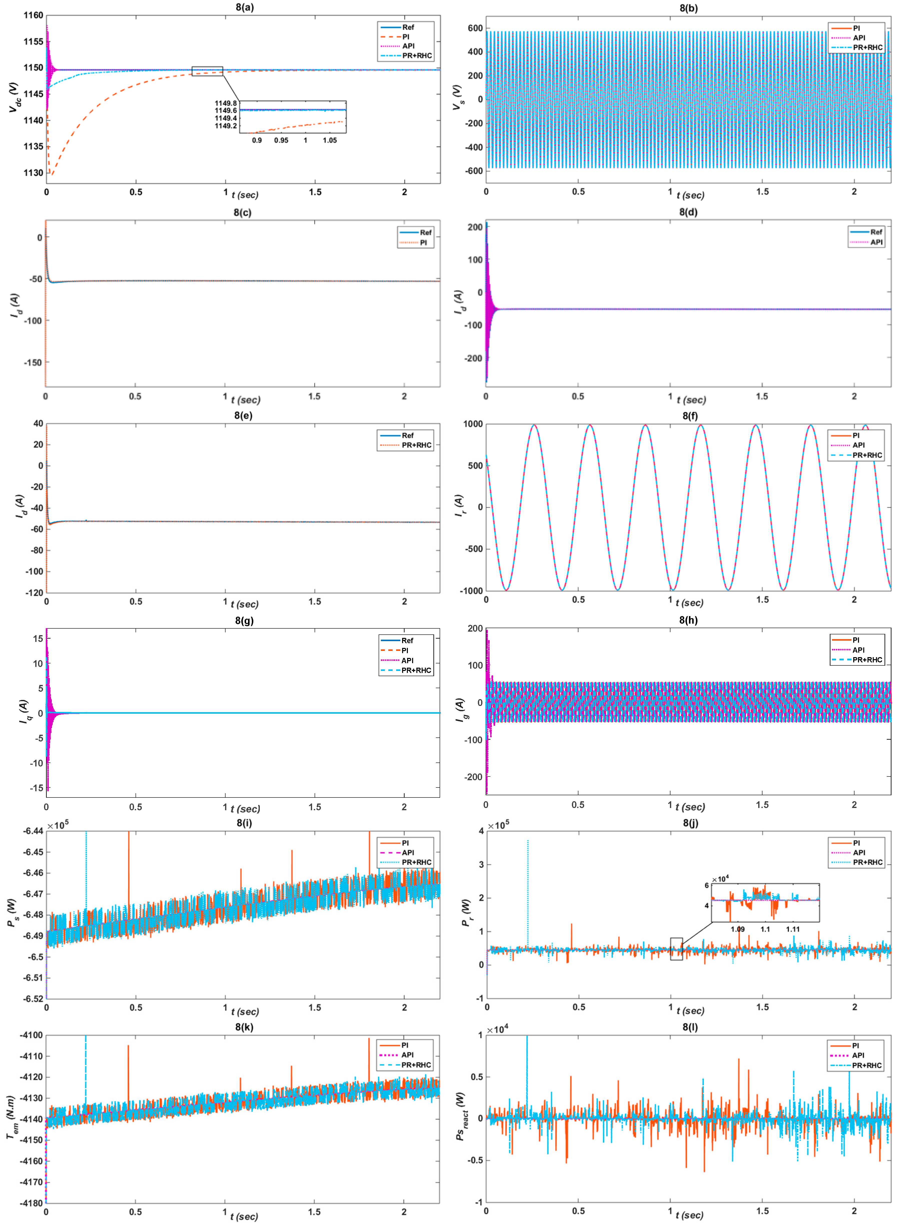
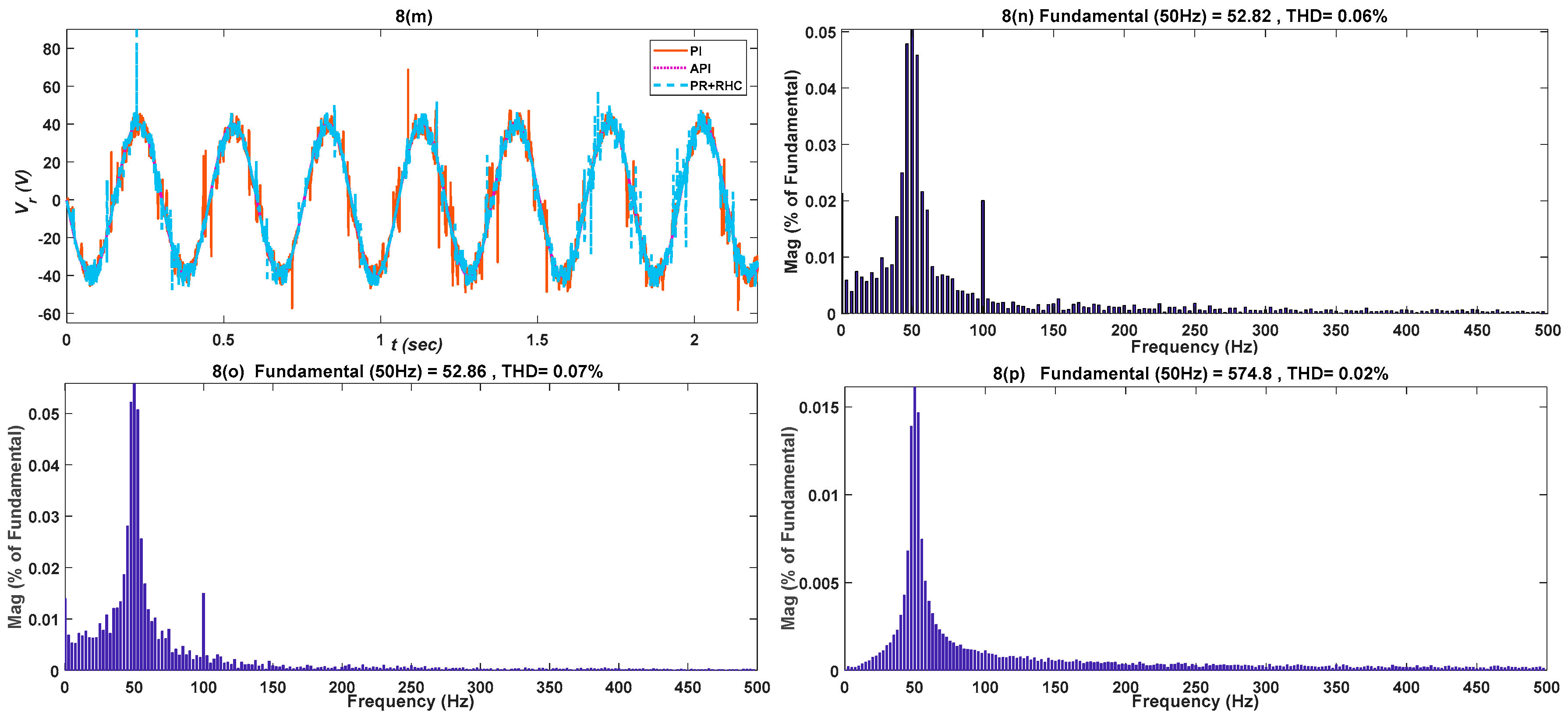
Figure 8.
Comparison of PI and Proposed API and PR+RHC controllers responses under rated voltage, considering: (a) Dc-link voltage ; (b) Stator voltage ; (c–e) Active component of current ; (f) Rotor current ; (g) Reactive component ; (h) Grid current ; (i) Stator active power ; (j) Rotor active power ; (k) Electromagnetic torque ; (l) Stator reactive power ; (m) Rotor voltage ; (n) PR+RHC controller THD; (o) PI controller THD; (p) API controller THD.
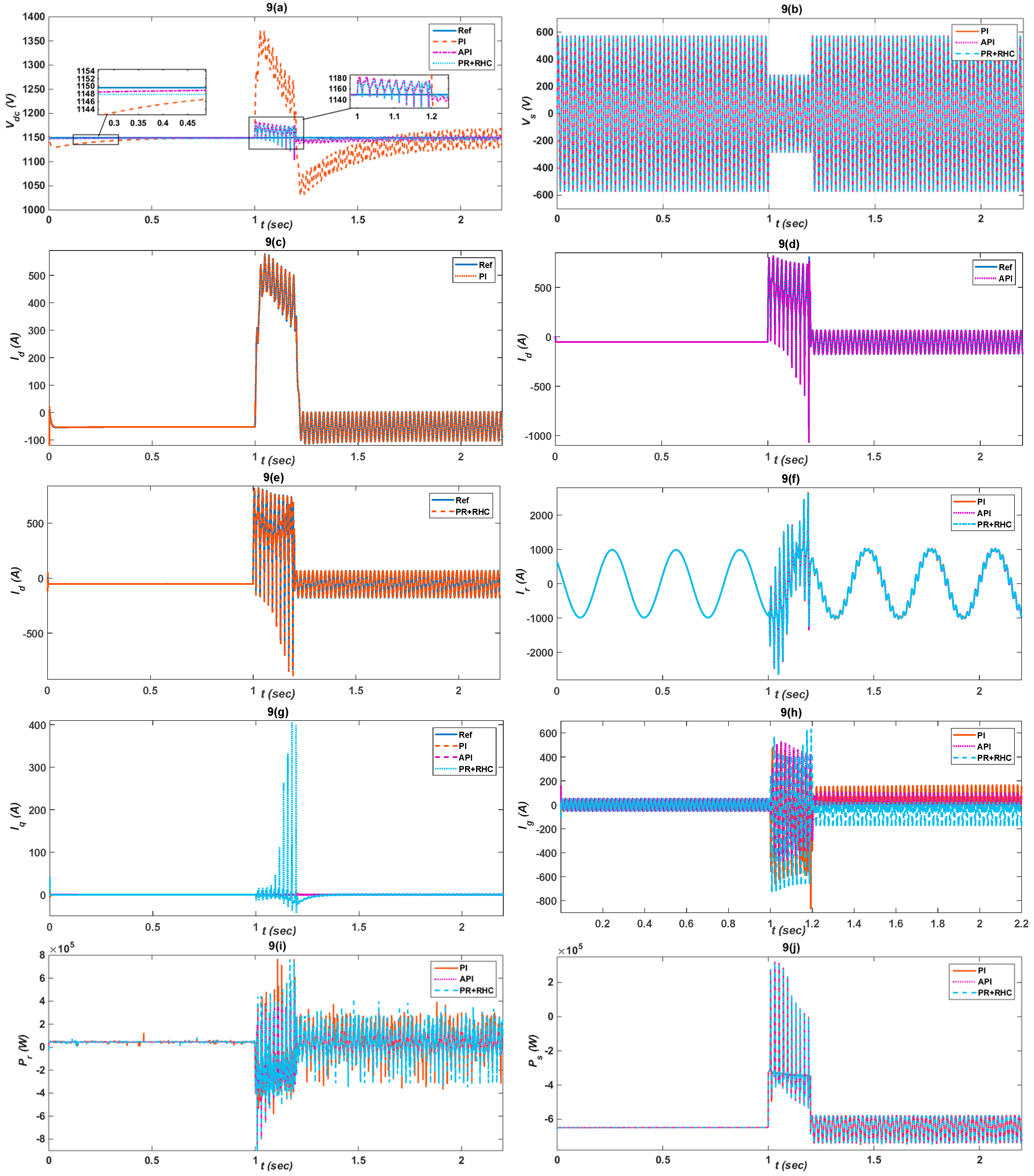
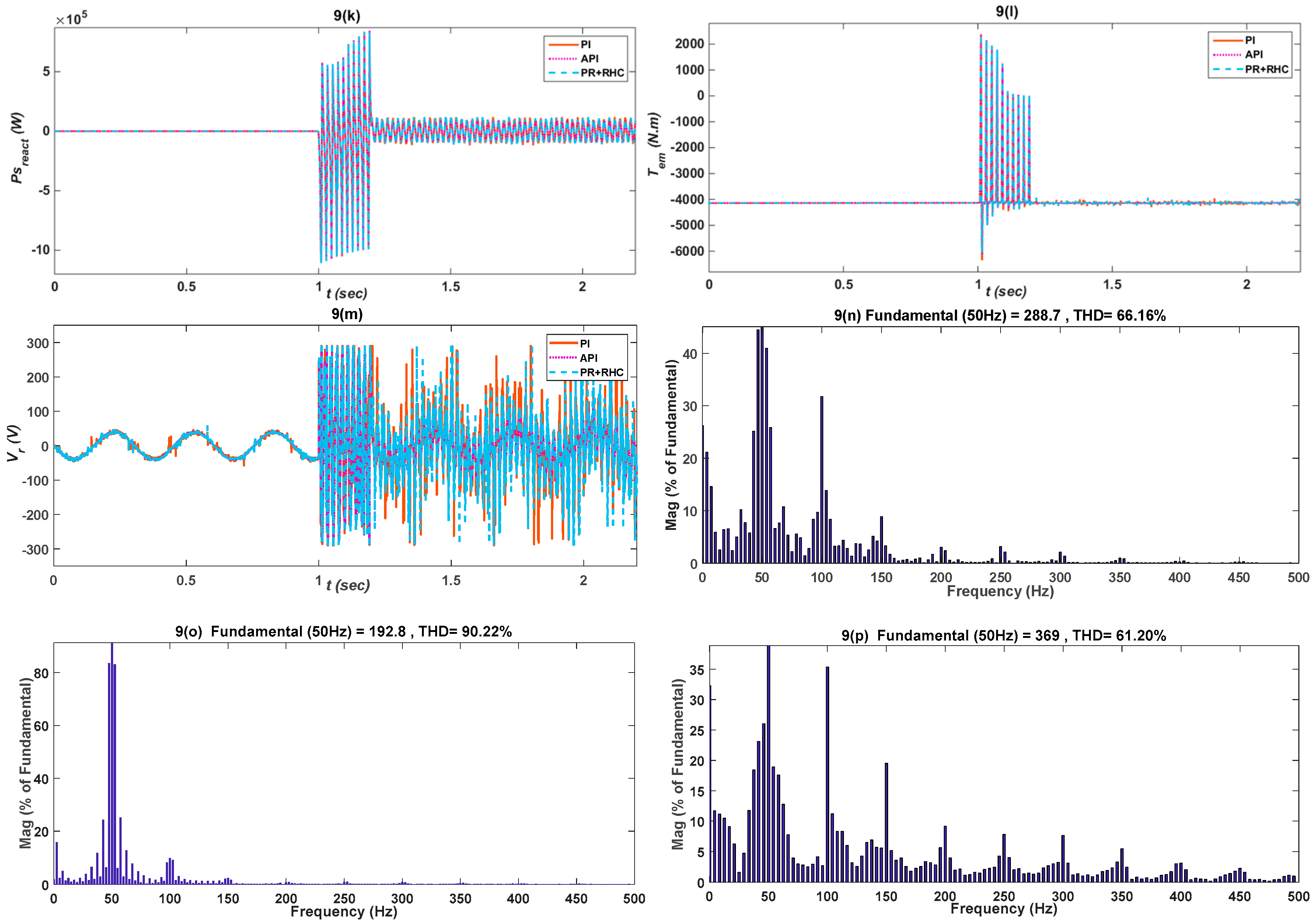
Figure 9.
Comparison of PI and Proposed API and PR+RHC controller responses under undervoltage fault considering: (a) Dc-link voltage ; (b) Stator voltage ; (c–e) Active component of current ; (f) Rotor current ; (g) Reactive component ; (h) Grid current ; (i) Rotor active power ; (j) Stator active power ; (k) Electromagnetic torque ; (l) Stator reactive power ; (m)Rotor voltage ; (n) PR+RHC controller THD; (o) PI controller THD; (p) API controller THD.
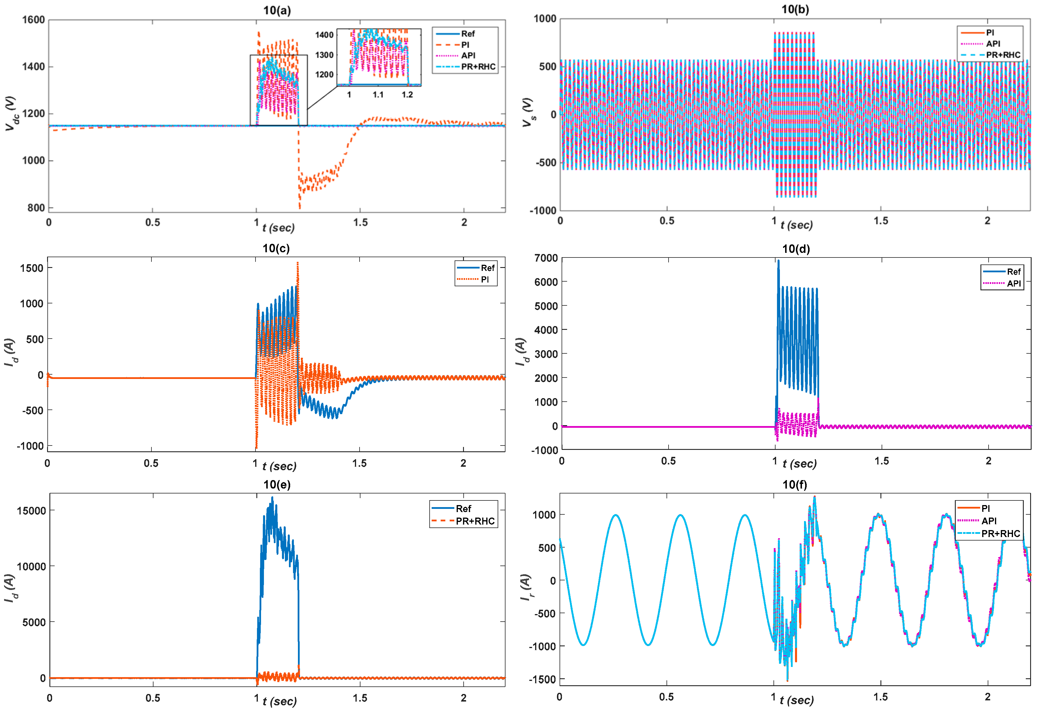
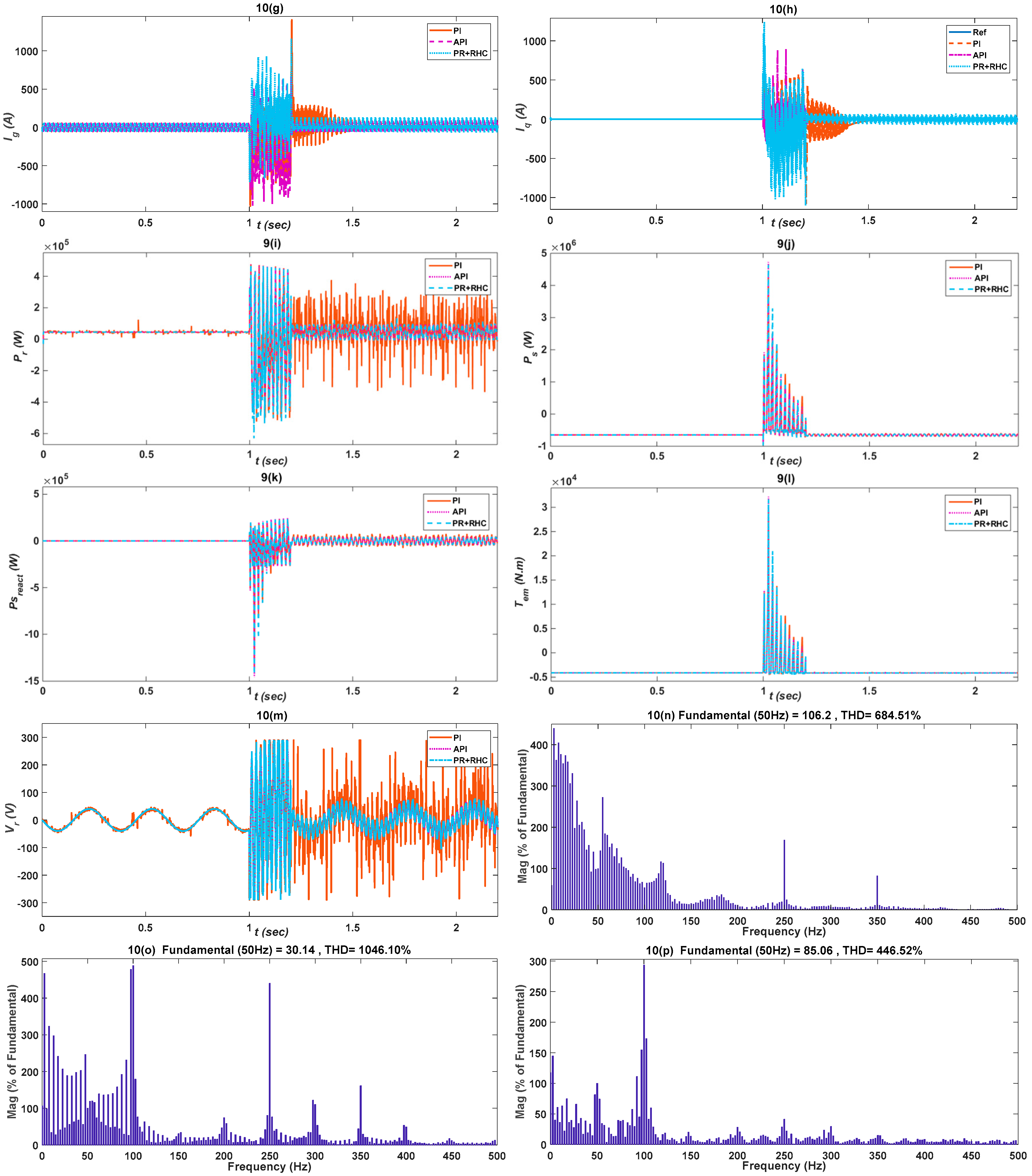
Figure 10.
Comparison of PI and Proposed API and PR+RHC controller responses under overvoltage fault, considering: (a) Dc-link voltage ; (b) Stator voltage ; (c–e) Active component of current ; (f) Rotor current ; (g) Reactive current component ; (h) Grid current ; (i) Rotor active power ; (j) Stator active power ; (k) Electromagnetic torque ; (l) Stator reactive power ; (m) Rotor voltage ; (n) PR+RHC controller THD; (o) PI controller THD; (p) API controller.
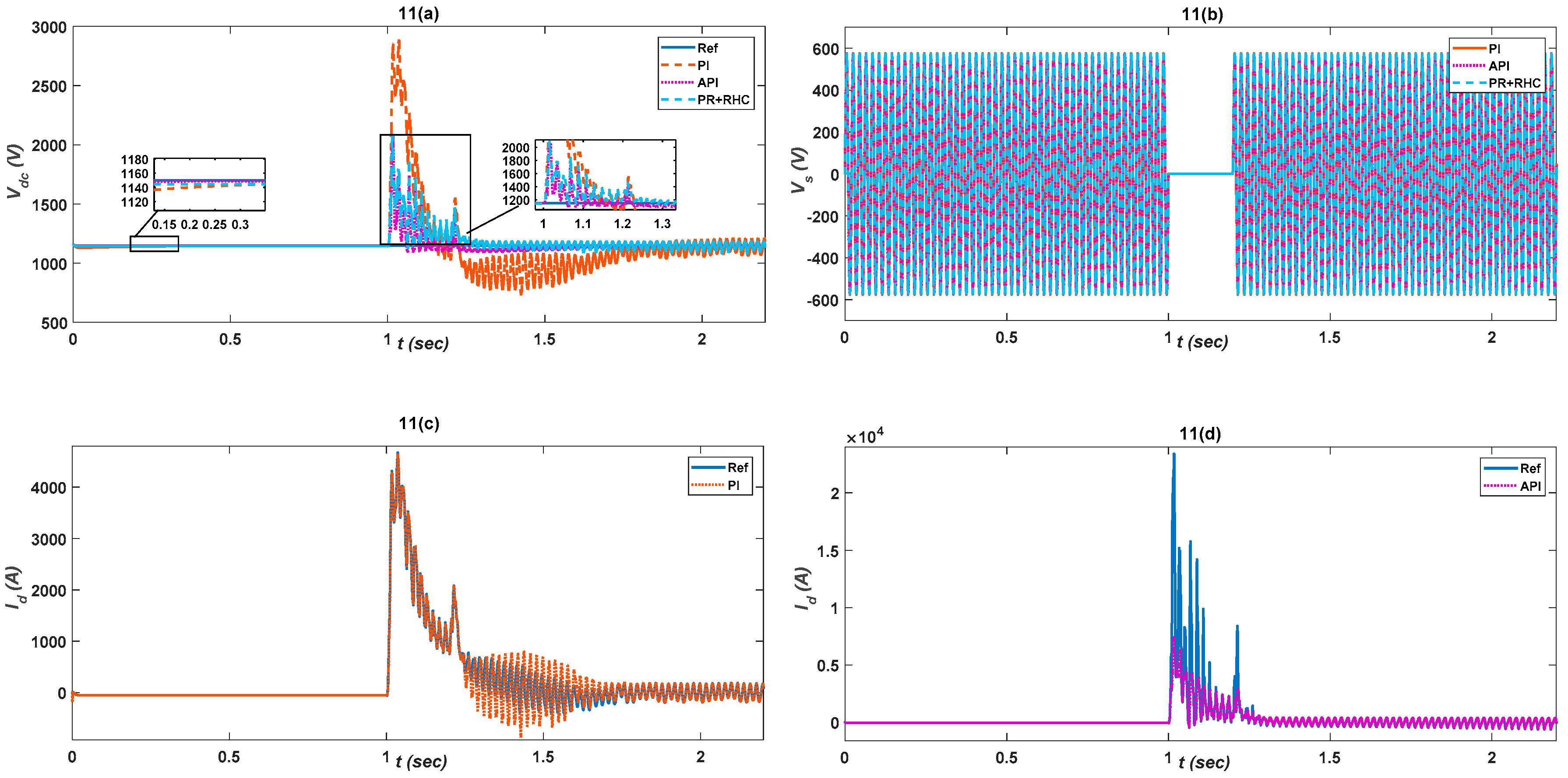
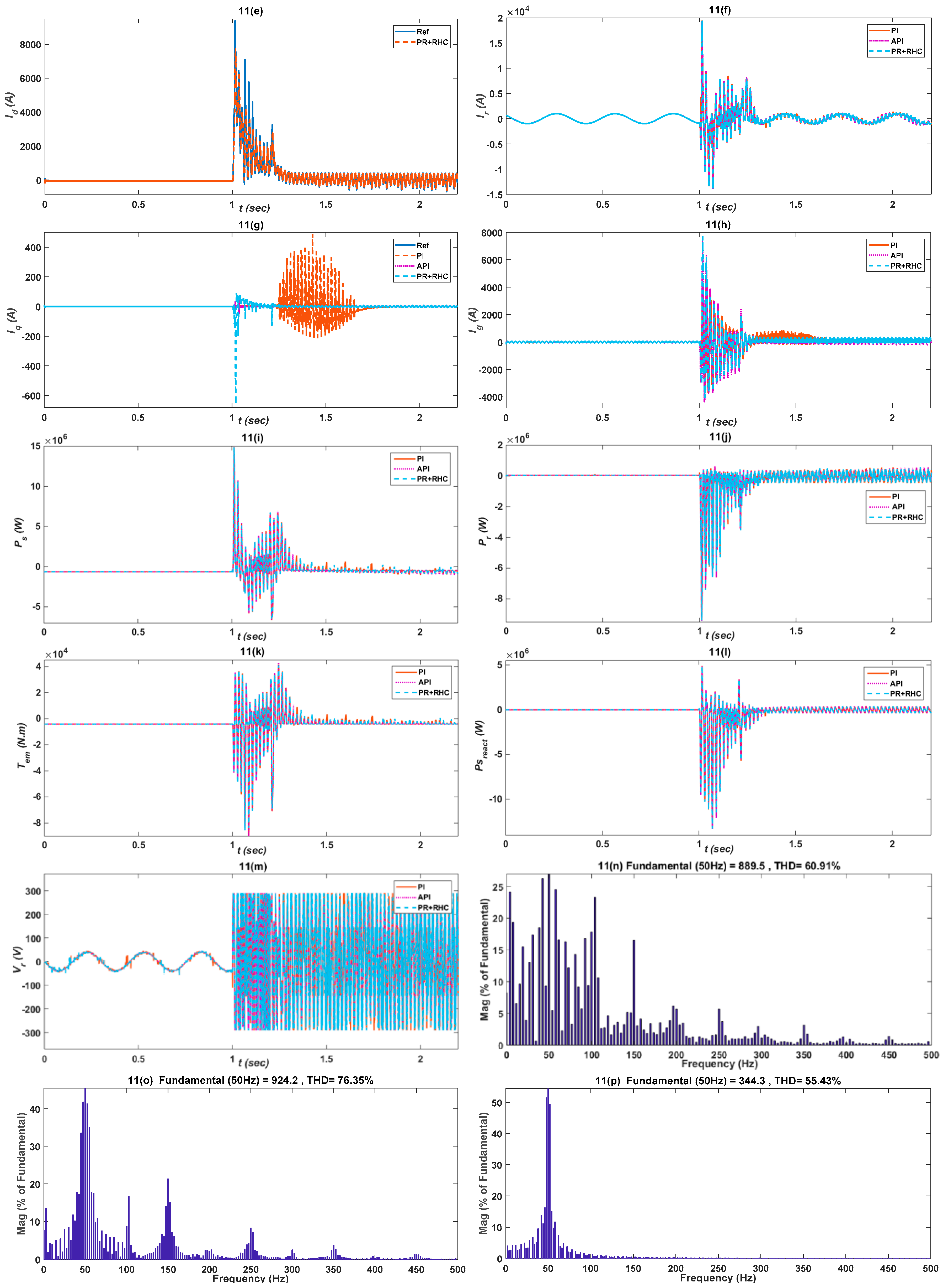
Figure 11.
Comparison of PI and Proposed API and PR+RHC controller responses under Single-phase fault, considering: (a) Dc-link voltage , (b), Stator voltage , (c–e) Active component of current , (f) Rotor current , (g) Reactive component , (h) Grid current , (i) Stator active power , (j) Rotor active power , (k) Electromagnetic torque , (l) Stator reactive power , (m) Rotor voltage , (n) PR+RHC controller THD, (o) PI controller THD, (p) API controller.
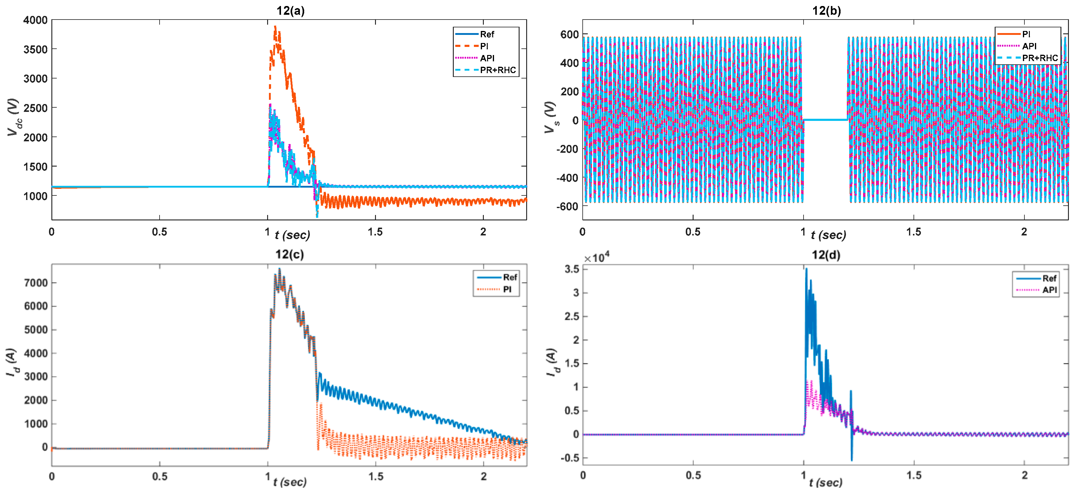
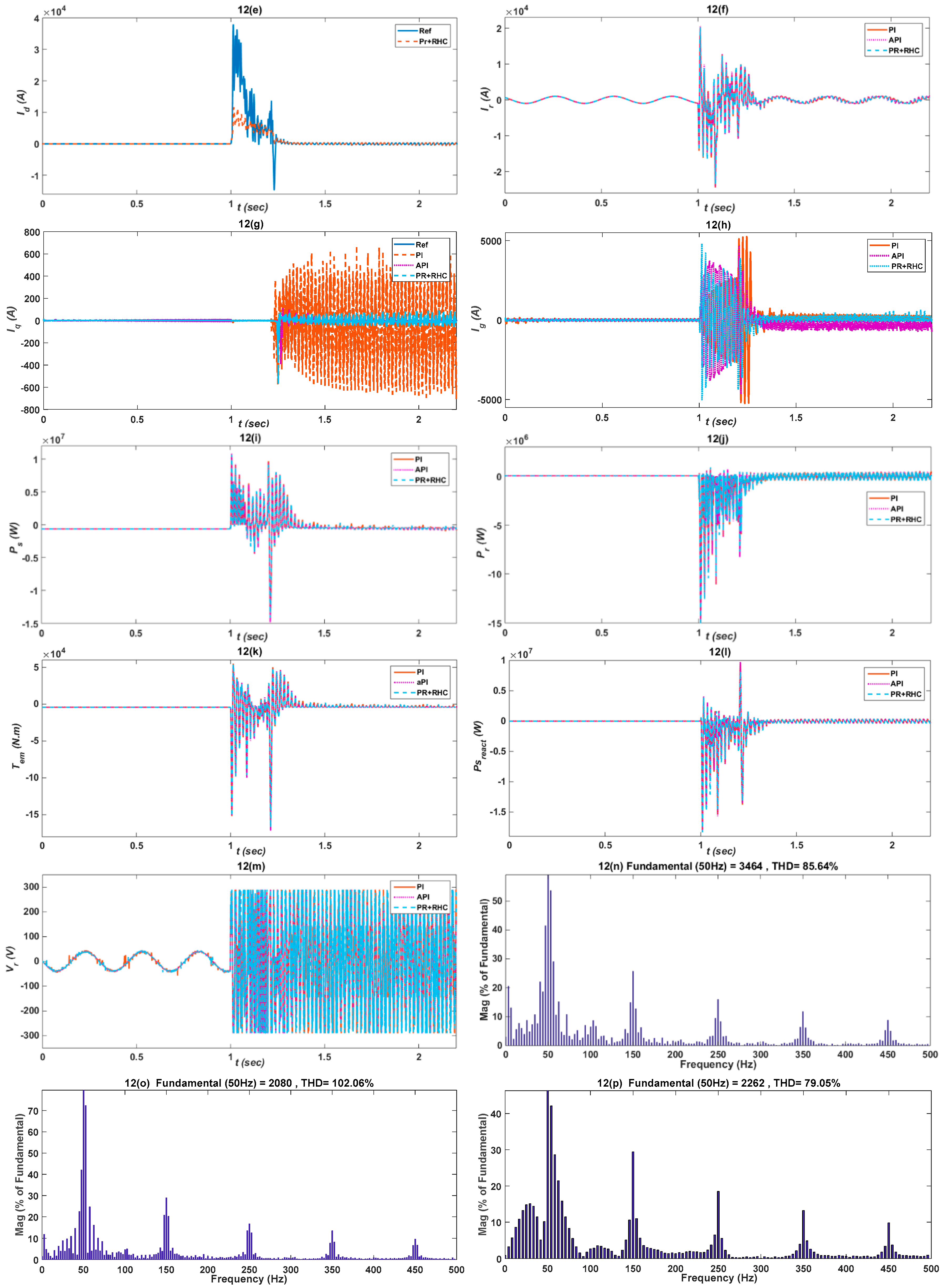
Figure 12.
Comparison of PI and Proposed API and PR+RHC controller responses under two-phase fault, considering: (a) Dc-link voltage , (b) Stator voltage , (c–e) Active component of current , (f) Rotor current , (g) Reactive component , (h) Grid current , (i) Rotor active power , (j) Stator active power , (k) Electromagnetic torque , (l) Stator reactive power , (m) Rotor voltage , (n) PR+RHC controller THD, (o) PI controller THD and (p)API controller.
Table 1.
Fuzzy rules.
| Absolute Error | Proportional Gain | Integral Gain |
|---|
| Zero | large | small |
| Small | large | zero |
| Large | large | large |
Table 2.
Performance evaluation of designed control strategies for Vdc.
Table 2.
Performance evaluation of designed control strategies for Vdc.
| Control Strategies | Performance Index |
|---|
| IAE | ISE | ITAE |
|---|
| PI | 5.473 | 55.95 | 1.991 |
| API | 0.1145 | 0.659 | 0.0810 |
| PR+RHC | 0.46 | 1.37 | 0.0325 |
Table 3.
Performance evaluation of designed control strategies for Id.
Table 3.
Performance evaluation of designed control strategies for Id.
| Control Strategies | Performance Index |
|---|
| IAE | ISE | ITAE |
|---|
| PI | 2.50 | 20.78 | 0.0749 |
| API | 0.96 | 6.34 | 0.0224 |
| PR+RHC | 0.0117 | 5.68 | 0.0094 |
Table 4.
Performance evaluation of designed control strategies for Iq.
Table 4.
Performance evaluation of designed control strategies for Iq.
| Control Strategies | Performance Index |
|---|
| IAE | ISE | ITAE |
|---|
| PI | 0.18 | 1.208 | 0.0066 |
| API | 0.01 | 0.062 | 0.0016 |
| PR+RHC | 0.017 | 0.069 | 0.004 |
Table 5.
Performance evaluation of the designed control strategies for Vdc.
Table 5.
Performance evaluation of the designed control strategies for Vdc.
| Control Strategies | Performance Index |
|---|
| IAE | ISE | ITAE |
|---|
| PI | 99.7 | 6240 | 211.8 |
| API | 16.2 | 120.8 | 37.46 |
| PR+RHC | 13.36 | 98.36 | 29.90 |
Table 6.
Performance evaluation of the designed control strategies for Id.
Table 6.
Performance evaluation of the designed control strategies for Id.
| Control Strategies | Performance Index |
|---|
| IAE | ISE | ITAE |
|---|
| PI | 18.74 | 583.4 | 53.43 |
| API | 3.015 | 142.1 | 5.431 |
| PR+RHC | 4.59 | 154.26 | 6.55 |
Table 7.
Performance evaluation of the designed control strategies for Iq.
Table 7.
Performance evaluation of the designed control strategies for Iq.
| Control Strategies | Performance Index |
|---|
| IAE | ISE | ITAE |
|---|
| PI | 1.601 | 0.8957 | 4.672 |
| API | 0.0019 | 0.0021 | 0.0024 |
| PR+RHC | 0.026 | 0.102 | 0.069 |
Table 8.
Performance evaluation of the designed control strategies for Vdc.
Table 8.
Performance evaluation of the designed control strategies for Vdc.
| Control Strategies | Performance Index |
|---|
| IAE | ISE | ITAE |
|---|
| PI | 55.17 | 23.86 | 70.02 |
| API | 10.49 | 4.09 | 15.63 |
| PR+RHC | 14.49 | 6.89 | 9.02 |
Table 9.
Performance evaluation of the designed control strategies for Id.
Table 9.
Performance evaluation of the designed control strategies for Id.
| Control Strategies | Performance Index |
|---|
| IAE | ISE | ITAE |
|---|
| PI | 5.6 | 35.26 | 7.65 |
| API | 2.6 | 16.32 | 3.27 |
| PR+RHC | 3.1 | 15.36 | 4.09 |
Table 10.
Performance evaluation of the designed control strategies for Iq.
Table 10.
Performance evaluation of the designed control strategies for Iq.
| Control Strategies | Performance Index |
|---|
| IAE | ISE | ITAE |
|---|
| PI | 73.01 | 63.86 | 88.97 |
| API | 36.73 | 20.71 | 55.23 |
| PR | 35.29 | 19.06 | 49.74 |
Table 11.
Performance evaluation of the designed control strategies for Vdc.
Table 11.
Performance evaluation of the designed control strategies for Vdc.
| Control Strategies | Performance Index |
|---|
| IAE | ISE | ITAE |
|---|
| PI | 366.1 | 63.23 | 754.1 |
| API | 80.64 | 32.36 | 170.7 |
| PR+RHC | 84.64 | 39.36 | 111.7 |
Table 12.
Performance evaluation of the designed control strategies for Id.
Table 12.
Performance evaluation of the designed control strategies for Id.
| Control Strategies | Performance Index |
|---|
| IAE | ISE | ITAE |
|---|
| PI | 190.4 | 5.323 | 35.5 |
| API | 0.20 | 1.916 | 0.25 |
| PR+RHC | 1.06 | 3.09 | 2.36 |
Table 13.
Performance evaluation of the designed control strategies for Iq.
Table 13.
Performance evaluation of the designed control strategies for Iq.
| Control Strategies | Performance Index |
|---|
| IAE | ISE | ITAE |
|---|
| PI | 45.59 | 456 | 73.66 |
| API | 11.58 | 154 | 15.51 |
| PR+RHC | 15..69 | 93 | 29.6 |
Table 14.
Performance evaluation of the designed control strategies for Vdc.
Table 14.
Performance evaluation of the designed control strategies for Vdc.
| Control Strategies | Performance Index |
|---|
| IAE | ISE | ITAE |
|---|
| PI | 96.39 | 12.36 | 96.4 |
| API | 24.4 | 2.36 | 35.32 |
| PR+RHC | 29.31 | 3.59 | 39.85 |
Table 15.
Performance evaluation of the designed control strategies for Id.
Table 15.
Performance evaluation of the designed control strategies for Id.
| Control Strategies | Performance Index |
|---|
| IAE | ISE | ITAE |
|---|
| PI | 65.75 | 37.77 | 51.23 |
| API | 9.32 | 13.26 | 17.34 |
| PR+RHC | 14.60 | 19.32 | 24.09 |
Table 16.
Performance evaluation of the designed control strategies for Iq.
Table 16.
Performance evaluation of the designed control strategies for Iq.
| Control Strategies | Performance Index |
|---|
| IAE | ISE | ITAE |
|---|
| PI | 59.32 | 16.96 | 86.36 |
| API | 15.30 | 6.32 | 19.32 |
| PR+RHC | 20.96 | 9.96 | 24.49 |

 ,
, 


