Abstract
Solar Photovoltaic (PV) systems have been in use predominantly since the last decade. Inverter fed PV grid topologies are being used prominently to meet power requirements and to insert renewable forms of energy into power grids. At present, coping with growing electricity demands is a major challenge. This paper presents a detailed review of topological advancements in PV-Grid Tied Inverters along with the advantages, disadvantages and main features of each. The different types of inverters used in the literature in this context are presented. Reactive power is one of the ancillary services provided by PV. It is recommended that reactive power from the inverter to grid be injected for reactive power compensation in localized networks. This practice is being implemented in many countries, and researchers have been trying to find an optimal way of injecting reactive power into grids considering grid codes and requirements. Keeping in mind the importance of grid codes and standards, a review of grid integration, the popular configurations available in literature, Synchronization methods and standards is presented, citing the key features of each kind. For successful integration with a grid, coordination between the support devices used for reactive power compensation and their optimal reactive power capacity is important for stability in grid power. Hence, the most important and recommended intelligent algorithms for the optimization and proper coordination are peer reviewed and presented. Thus, an overview of Solar PV energy-fed inverters connected to the grid is presented in this paper, which can serve as a guide for researchers and policymakers.
1. Introduction
Grid-tied photovoltaic systems are power-generating systems that are connected with grids. Solar PV energy that is generated must be processed with the help of a grid-connected inverter before putting it to use. This inverter is present between the solar PV arrangement and the utility grid; it could be a single unit or a collection of small inverters attached to the individual PV units. Due to the lowered cost of power electronic devices and advancements in renewable energy technology, there is significant encouragement for the power industry to utilize PV solar energy and to attach it to a medium or low voltage distribution grid. The renewable electrical energy market has experienced an extraordinary increase in scope in recent years. Its main catalyst in 2016 was solar photovoltaics, whichare boosting the capacity of renewables all over the world. Due to reductions in costs, solar and wind energy are playing an increasingly important role and are proving to be competitive with fossil fuels in many countries. Two-thirds of overall electricity additions in 2016 were from renewable sources of energy [1]. According to the International Energy Agency, solar is leading in additions compared to wind and hydropower. The statistics of net additions and retirements in electricity capacity are shown in Figure 1.
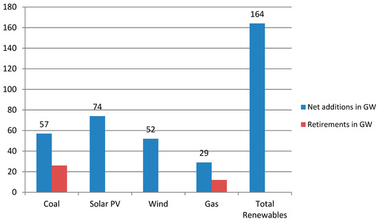
Figure 1.
Net additions and retirements of Electricity capacity in 2016. Reproduced from [1], International Energy Agency: 2017.
From [2], it is noted that Solar PV has dominated all other forms of electricity production. Its capacity comprises almost 600 Giga Watt (GW) more than all other forms of energy combined. Thus, with this increasing trend in use of Solar PVs, it becomes even more important to study the obstacles faced in extracting energy from solar PV systems and then exporting it or integrating it with the grid. The primary factors to be borne in mind while integrating PV solar energy with the grid are:
- Reducing the cost during power conversion stage
- Improving the reliability of the converter in use
- Reducing the harmonics in the output current obtained
- Reducing the number of switches/components used in grid integration
- Ensuring continuity in supply by providing back up power for PVs.
- Controlling the real and reactive power
- Maintaining a constant direct current (DC) link voltage via a suitable control scheme
- Detecting the maximum power point of PV panel using Maximum Power Point Tracking (MPPT) techniques.
Henceforth, a detailed review is done, keeping in mind the current trend and effectiveness of energy produced, and the simplicity of its integration with the grid. This paper is organized as follows:
2. Ancillary Services in Electric Market
2.1. Definitions of Ancillary Service
In this section, a brief introduction to ancillary services has been given with standard definitions from the literature. An insight to Reactive Power (Q) being an ancillary service is provided. In order to understand the concept of ancillary services, a few definitions from the literature have been listed here.
- *
- As per International Electro technical Commission (IEC) 60050-617, ancillary services are “services necessary for the operation of an electric power system provided by the system operator and/or by power system users” [3].
- *
- According to the Union of Electric Industry EURELECTRIC: “Ancillary Services are those services provided by generation, transmission and control equipment which are necessary to support the transmission of electric power from producer to purchaser. These services are required to ensure that the System Operator meets its responsibilities in relation to the safe, secure and reliable operation of the interconnected power system. The services include both mandatory services and services subject to competition” [3].
- *
- Federal Energy Regulatory Commission (FERC) defined ancillary services as those “necessary to support the transmission of electric power from seller to purchaser given the obligations of control areas and transmitting utilities within those control areas to maintain reliable operations of the interconnected transmission system” [4].
2.2. Popular Ancillary Services in Electric Power Market
Figure 2 shows some popular ancillary services in electric power market. They are:
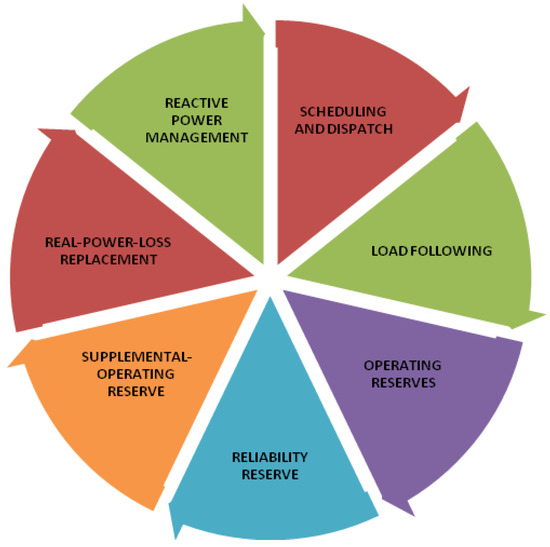
Figure 2.
Popular ancillary services in electric power market suggested by FERC.
- Q Management: Q Management is a service that is unbundled to both suppliers and consumers. A system operator can control this service but the control is limited to local control area. Q management is the same ancillary service as voltage control. Voltage control is done to balance voltages in accordance with the prescribed limits during different time slots of power transmission. Q injection and absorption leads to system stability and yields protection against unforeseen events that may cause voltage breakdown. Hence, reactive-power must be made available to meet the expected demand and serve as a reserve margin during emergencies.
- Real power (P) loss replacement: P loss is the variation in P generated and delivered. Due to resistance in each active and passive element in the transmission line, loss is unavoidable. International Organization for Standardization (ISO) should generate power online in order to cope up with P losses although suppliers also make up for the losses.
- Supplemental operating reserve: Supplemental-operating reserve includes generating units, which must supply power within ten minutes and must be completely available within thirty minutes.
- Reliability reserve: Reliability reserve includes generating units and spinning reserves, which must be made available completely within ten minutes.
- Operating reserve: Operating reserve ancillary service is used to balance the power generation to the load because of unexpected outages.
- Load following: Load-following ancillary service includes two functions performed by the control area (interconnection frequency maintenance and load balance) and two more functions performed by customer (monitoring fluctuations in load and keeping in track of long-term changes). Thus, there are four different components in load following ancillary service.
- Scheduling and dispatch: Scheduling is a separate ancillary service and not connected to dispatch, but they are lumped together since they are less expensive and coordinated by ISO. Scheduling is to anticipate load requirement and assign generating units accordingly. Dispatch is the actual control of generation units and transmission units, which are available in order to satisfy the load demand. Scheduling, as well as dispatch, are quite inexpensive.
2.3. Additional Services in Electric Power Market
Figure 3 shows additional services in electric power market suggested by FERC. They are:
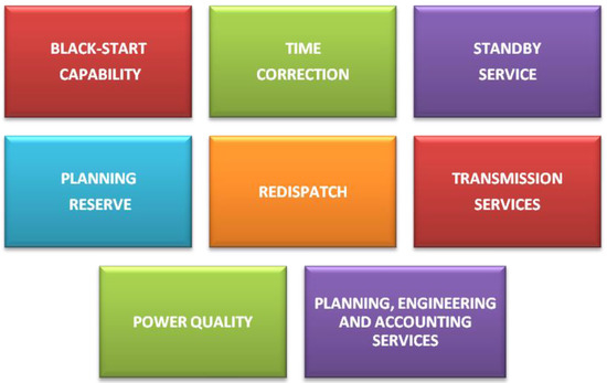
Figure 3.
Additional services in electric power market suggested by FERC.
- Black start capability: Under certain conditions in which the system collapses, drawing power from the grid becomes an impossible event. Thus, some special generating units called black start units are used to restart devoid of taking power from grid.
- Time correction: Generally, most of the electrical clocks work by means of counting the cycles in the frequency of power. Although this frequency is kept constant, there will be an error of 0.01 Hz. If time correction were not done, there would be an error of roughly 10 s a day considering 50 Hz cycle.
- Standby Service: Standby service serves as a generating capacity, which is kept at reserve to supply energy when emergencies occur. Standby capacity is used in circumstances in which a customer’s power is interrupted due to an outage or when the generating unit is under scheduled maintenance or when a customer’s power demand exceeds the actual contracted one.
- Planning Reserve: It serves as a planned generating unit based on customer requirement. Hence, it is a customized one and cannot be the same for all customers.
- Redispatch: Due to transmission losses and constraints, least cost power dispatch is not possible. This is known as congestion. In order to avoid congestion, redispatch is done to adjust the power that is input to the transmission line. This method is applied within control areas.
- Transmission Services:
- Transmission system monitoring and control
- Transmission reserves
- Repair and maintenance of the transmission network
- Metering, billing and communications.
- Power Quality: Power quality means provision of uninterrupted power which is purely sinusoidal to customers
- Planning, Engineering & Accounting Services:
- Planning services:
- Load forecasting
- Scheduling
- Coordination of the maintenance of generating units
- Coordination of power transmission maintenance and power outages.
- Engineering services:
- Black-start studies
- Load-flow analysis
- Planning for bulk-power system expansion.
- Accounting services:
- Scheduling
- Billing
- Contract administration
- Reporting to several regulatory bodies.
2.4. Q Injection to Grid
One of the primary ancillary services that is necessary for a power system operator is Q injection to grid [5]. In Figure 4, the red curve indicates the capability of the PV inverter to provide Q. Furthermore, based on the voltage at point of common coupling (PCC), freedom of having higher current distortion is permissible. Several countries have added Reactive power injection to grid into the countries’ standard grid code (GC) requirements. In general, if a country follows standard GC, power generation by PVs is required to cease immediately when there is a fault occurring in the grid. However, because of high level of penetration of PVs into grid, a sudden and quick power interruption due to a fault in the grid would cause severe problems. For to this reason, many countries like Spain, Italy, Germany and Japan have modified their GCs [6,7,8,9].
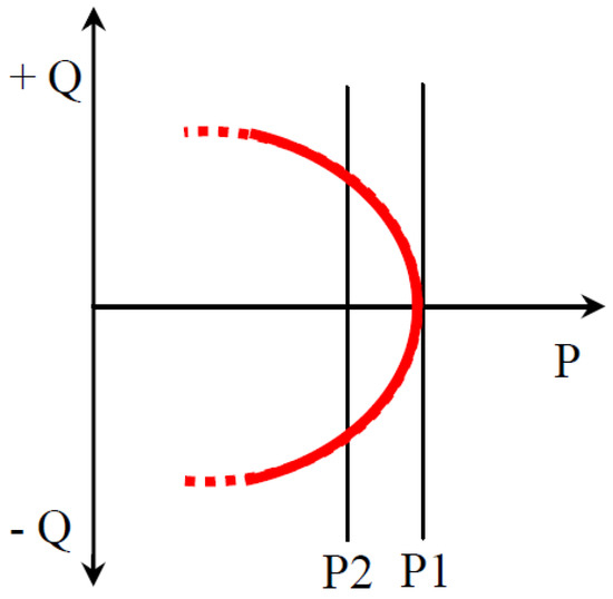
Figure 4.
PV inverter reactive power capability based on current limits.
There are numerous services that can be extracted with the use of PVs. Figure 5 shows some of the important ancillary services involving solar PVs. It can be noted that ancillary services provided by PV systems open an important pathway in electric power market and Q injection to grid has been area of research for the last three decades [10,11,12,13,14,15,16,17,18,19,20,21,22].
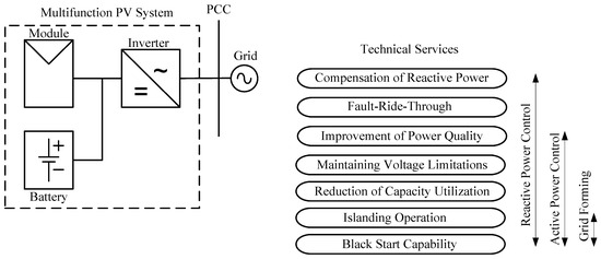
Figure 5.
Services provided by PV systems.
Solar-PV panels do not possess Q, since they provide electric power by using PV effect. The power conversion from DC of solar panels to AC injected to grid takes place due to inverter circuitry. This inverter has the capability of providing Q support in fault/normal conditions. Inverters could provide various other ancillary services. Some of these such as lowvoltage ride-through (LVRT) and MPPT have become necessary. Although, Q support has not been made mandatory for grid connected PV systems, the higher penetration levels of PVs indicate more accessibility to control of P and Q. Hence, it would become a code included in GCs of all countries using more renewable form of power conversion. In general, for PV-grid topologies, the inverter converts the DC of PV panels to alternating current (AC) that is to be supplied to grid. Figure 6 shows a single-phase PV-grid system that can be used for requirements up to 7 kW. There are many types of inverters that are used in a PV-grid scenario. In the following section, a brief summary of inverter topologies for use in grid-connected systems is provided.
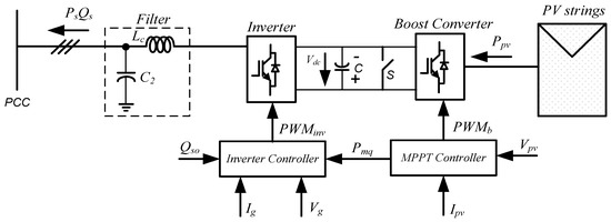
Figure 6.
A sketch of single-phase PV-grid system.
3. PV-Grid Inverters—A Summary of Different Topologies
Numerous works have been proposed in literature to illustrate various topologies of inverters including state-of-art review [23]. Traditional inverters such as voltage source inverter (VSI) and current source inverter (CSI) have a major drawback, i.e., voltage buck and boost actions cannot take place simultaneously. In order that buck and boost actions take place collectively, an additional converter has to be added in the circuitry, making the whole system more expensive. Popular impedance source inverters (ZSIs) have been discussed in the literature; they have the ability to overcome the major disadvantage of involving a two-stage topology in power conversion. Both boosting and bucking actions are possible with this topology. ZSI is a combination of VSI and CSI. Boosting of voltage takes place at the DC link with the help of a unique technique called shoot-through [24,25]. In recent years, an interesting inverter topology namely admittance source inverter (YSI) was introduced. The following section gives an overview on different inverter topologies available in literature.
3.1. Traditional Inverters Vs Multilevel Inverters
One of the traditional configurations of inverters that is connected to power grid is VSI (shown in Figure 7). In VSIs, the output voltage is always lesser than the input voltage. VSIs have the ability to introduce currents with low harmonics into the grid. When a CSI (shown in Figure 8) is used instead of VSI, current injection to grid can take place without the need of an additional converter. The output from a VSI and CSI comprises of two unique levels of voltage, but it suffers from higher switching losses. The rate of change of voltage (dv/dt) is higher for traditional two-level inverters. The frequency of switching is also high. They are most suited for low voltage applications.
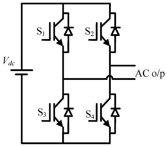
Figure 7.
Voltage source inverter.
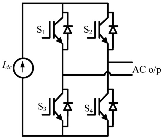
Figure 8.
Current source inverter.
Multilevel inverters (MLIs) were introduced to overcome the drawbacks of traditional inverters. The classification of MLIs is given in Figure 9. Switching losses are a main factor of concern in two level inverters. Using MLIs, they can be minimized.MLIs aid to reduce switching losses and harmonics. They can be used for high voltage applications. The rate of change of voltage (dv/dt) is lesser for MLIs. The levels of voltage could be increased to greater than two. Hence, apure sinusoidal waveform is obtained as the output of the inverter. The harmonics in the output are mitigated and losses could be reduced largely. With the introduction of multilevel topology in CSI (shown in Figure 10), low harmonic currents are obtained. The frequency at which the switching action takes place is reduced with the introduction of a multilevel topology for a current source inverter. A brief comparison between traditional inverters and multilevel inverters is presented in Table 1. Table 2 summarizes the state of art PV grid inverter topologies of MLIs.
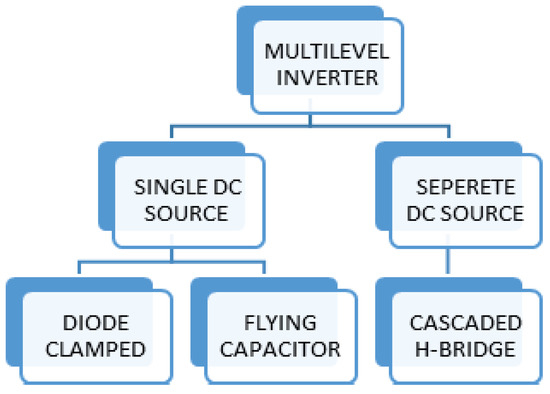
Figure 9.
Classification of multilevel inverter topologies.
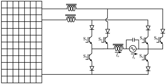
Figure 10.
A multilevel CSI topology.

Table 1.
Traditional two-level inverters Vs MLI.
Table 2.
State of art PV grid inverter topologies of MLIs.
3.2. Concept of Z Source and Its Application in Solar Industry
Even though multilevel inverters have shown better performance than traditional inverters, they still have drawbacks. The number of switches is quite high in an MLI. Although the switches required need smaller rating, the number of required switches is high, thus making the circuit complex and costly. Thus, ZSIs with several advantages over the aforementioned inverters were introduced. Figure 11 shows a voltage fed ZSI.
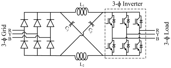
Figure 11.
A voltage fed ZSI.
A ZSI is a combination of inductors and capacitors. A ZSI would operate as a VSI or CSI depending on the application. The output voltage ranges from zero to infinity. Many researchers have adapted impedance source topologies and many advances in the topologies have been listed in literature like YSIs and their advancements [26,27] and ZSIs and their advancements [28,29,30,31,32,33,34,35,36,37,38,39,40,41,42,43,44,45,46,47,48,49,50,51,52,53,54,55,56,57,58,59,60,61,62,63,64,65]. Figure 12a–c give an overall classification of topologies of impedance source networks. A summary of these topologies, as presented in different literature works, is presented in the following section.
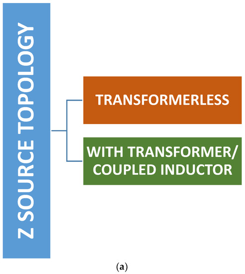
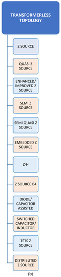
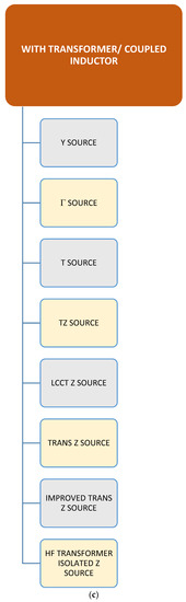
Figure 12.
(a) Broad classification of Z source network topologies. (b) Classificztion of Z source transformerless topologies. (c) Classification of Z source topologies with transformer/coupled inductor.
Solar modules are widely preferred in both residential and commercial applications. PV cells are connected in parallel and series in order to form one module. Many such modules in combination is a panel. To develop economical and efficient PV systems, MPPT algorithms are used. Generally, the inverter portion of the PV-inverter-grid structure comprises of a boost circuit and a filter. MPPT algorithms may or may not be used depending upon the application. In PV systems, in order to obtain dc-ac conversion, ZSI is an intelligent choice [66]. ZSIs can boost the voltage levels with a very compact structure. For a 10 kilowatt (kW) PV system, 20 kW inverter is required with a traditional inverter but by using ZSIs, a 10 kW inverter is enough for a 10 kW PV system with same kilo volt-ampere (KVA) maintained. Traditional inverters pose challenges in their control and modulation mmechanisms. These issues are eradicated using ZSIs.
The boost factor for a simple boost control method can be obtained from Equations (1)and (2) where M is the modulation index, and B is the Boost factor, T is the total time-period, which is one complete cycle. T0 is the time-period for which the output waveform is obtained.
Summaries of stateof the art PV-grid inverter topologies of Z source networks without transformer and with transformer/coupled inductor arepresented in Table 3 and Table 4 respectively. The features of each structure with components used, including passive elements and semiconductor devices peer reviewed from different literature works are listed. Detailed topological figures can be obtained from the respective reference papers cited for each structure listed in the tables.
Table 3.
State of art PV grid inverter topologies of transformer less Z source networks.
Table 4.
State of art PV grid inverter topologies of Z source networks with transformer/coupled inductor.
- NOS—Number of semiconductor devices
- NOC—Number of capacitors
- NOL—Number of inductors
3.3. Grid Integration Configurations, Synchronization& Standards
Grid-integrated PV systems could be of various power levels and sizes. They are designed for specific applications and needs, with a scope ranging from one PV module to over 100 MW [69]. Hence, a generic PV-inverter-grid structure, as shown in Figure 13, could vary for each plant.
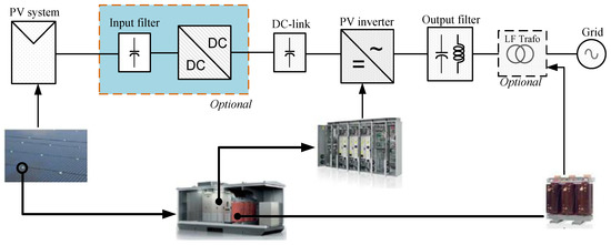
Figure 13.
A generic structure of a PV-inverter-grid structure (Picture courtesy of ASEA Brown Boveri).
In order to make things seem less complex, PV-grid systems are divided based on power rating into
- Small scale (a few Ws a few tens of kWs)
- Medium scale (a few tens of kWs to a few hundreds of kWs) and
- Large scale (a few hundredkWs to several hundreds of MWs).
Table 5 gives a summary of PV-grid-inverter configurations along with pros and cons of each configuration to provide a clear-cut guidance in choosing the type of system depending upon the requirements.
Table 5.
PV grid inverter configurations—An Overview.
Synchronization of the inverter with the grid is a major challenge in grid integration. Typically, inverters operate like current sources that inject the current in phase with grid voltage [71]. Therefore, pf needs to be maintained at unity or near to unity while the grid is connected to an inverter system. The most important thing is the synchronization of the inverter with the grid voltage. The rule of thumb for synchronization is that the total real power of the grid must be equal to the voltage of the grid and current of the inverter summed. Based on the synchronization rule, the Equation (3) is derived.
Several methodologies can be studied from literature for synchronization of grid and PV inverter. Figure 14 gives a brief of literature works surveyed in this regard.Grid integration and the injection of current into the grid play a critical role in the operation of a grid connected PV system. Different works have highlighted current injection into the grid in accordance with recommended standards [72,73,74,75,76,77,78,79,80,81,82,83,84,85,86,87].
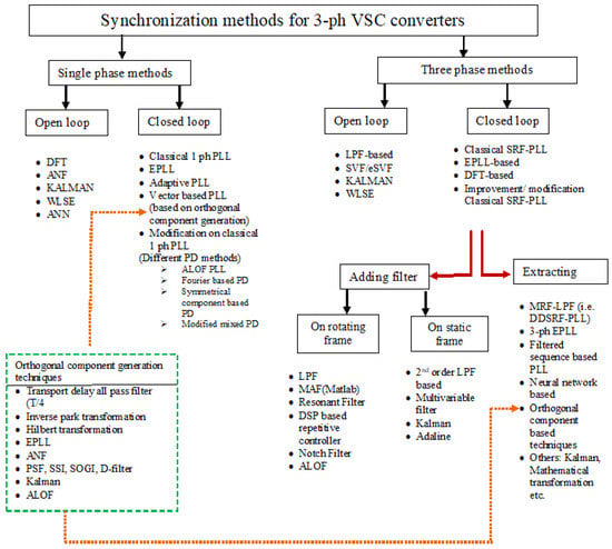
Figure 14.
PV-Grid Synchronization methods. Reproduced from [70], 14th European Conference on Power Electronics and Applications (EPE): 2011.
Due to the increase in PV-grid applications, many standards and GCs are proposed in order to have secure transmission of power into grid. Some of the well-known bodies that develop the standards are Institute of Electrical and Electronic Engineers (IEEE) of USA, IEC of Switzerland and Deutsche Kommission Elektrotechnik (DKE) of Germany. A summary of these standards and GCs is given in Table 6.
Table 6.
A Summary of International codes for PV applications.
4. A Summary of Intelligent Algorithms & Optimization Techniques in Grid-Tied Inverters
Due to a rapid increase in complexity, optimization has become necessary in the design of every system. When PVs are involved, it means that there is going to be intermittency in the output power. In order that the load is fed without any fluctuation, optimization techniques must be incorporated to get smoother and better output. In order to understand modern intelligent algorithms and optimization techniques, one must have an understanding on the computational intelligence, which is used along with optimization techniques. Figure 15 lists the computational intelligence platforms that are discussed briefly in the following section.
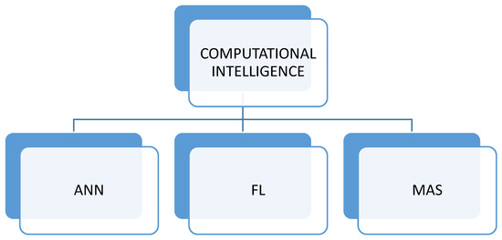
Figure 15.
Computational intelligence techniques.
- Artificial Neural Network (ANN):The ANN was originally introduced by Rosenblatt [85]; it is a replica of human brain, and is useful for forecasting the availability of renewable energy [86].
- Fuzzy Logic (FL): FLis used in decision making. The theory behind its application pertaining to current area of study can be found in [87], and the methodology for practical application in Renewable energy systems can be inferred from [88].
- Multiagent system (MAS): Every component in the system is represented as an agent with unique objectives. A detailed review on the subject can be studied in [89].
Figure 16a shows the classification of exact optimization depending on treatment of uncertainties. Figure 16b shows the classification of heuristic optimization. Table 7 lists the optimization techniques used in transmission and distribution systems with Q as one of the control variables. Table 8 summarizes various Q control techniques applied to the different sets of surveyed configurations.
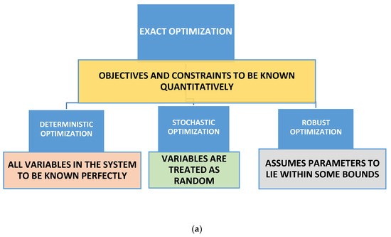
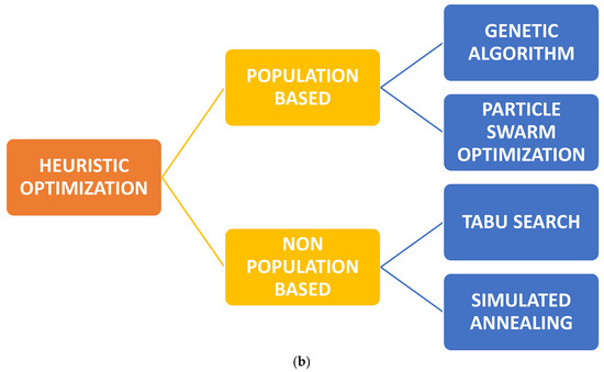
Figure 16.
(a) Classification of exact optimization depending on treatment of uncertainties. (b) Classification of Heuristic optimization.
Table 7.
A summary of literature works surveyed related to optimization.
Table 8.
A summary of control techniques surveyed.
5. Conclusions and Future Scope
Grid-tied inverter topologies are important components for the interface between the RER and the utility grid. Now, single-phase, transformerless configurations of range 1–10 kW are gaining interest. When compared to transformer-based configurations, the main advantages of transformerless configurations are:
- Less complexity
- Lower cost
- Higher efficiency
- Lighter weight
- Smaller volume
Thanks to the technological advancements in the area of power electronics, numerous transformerless inverters derived from conventional H-bridge topology have been developed. These inverters offer high efficiency and reliability. They also have lower electromagnetic interference, since transformers or coupled inductors are not involved in the design. In recent times, low-efficiency PV arrays have been widely used. In order to achieve maximal efficiency, the materials involved in fabrication of PV panels need to be carefully investigated and used. In this paper, a critical review of grid connected PV systems was performed. The definition of ancillary services and the reactive power market with reactive power as an ancillary service was examined. A review of the different topologies of inverters with special reference to state of art topologies such as y source inverter derivatives was presented. Unique aspects of each topology in terms of structure and functional merits/demerits were presented in detail. In the coming era, a basic understanding of power converters becomes necessary for the successful integration of PVs with grid. Fulfilling the GC requirements also becomes a major challenge. Hence, in this paper, the synchronization between the inverter and the grid was examined, with the aim of outlining important concepts in grid synchronization and standards. Finally, intelligent algorithms and optimization techniques surveyed from different literature works were listed. A summary of different works available in the literature has been presented with the aim of providing researchers with an overview ofgrid-connected architectures. With the advent of Perovskite material used in solar cells, solar technology has seen tremendous advances. Future work may focus on the manufacturing side of solar cells, since this is currently an area of great discussion.
Author Contributions
All authors contributed equally in this research activities for its final presentation as full research article.
Funding
This research received no external funding.
Conflicts of Interest
The authors declare no conflict of interest.
Nomenclature
| Acronyms | |
| AC | Alternating current |
| ACO | Ant colony optimization |
| ANN | Artificial neural network |
| BESS | Battery Energy storage system |
| CSI | Current source inverter |
| DC | Direct Current |
| DO | Deterministic Optimization |
| DVR | Dynamic voltagerestorer |
| DKE | Deutsche Kommission Elektrotechnik |
| EA | Evolutionary algorithm |
| EMF | Electromotive force |
| EMI | Electromagnetic interference |
| ESS | Energy storage system |
| FACTS | Flexible AC transmission system |
| FERC | Federal Energy Regulatory Commission |
| FL | Fuzzy logic |
| FRT | Fault ride-through |
| GA | Genetic algorithm |
| GC | Grid code |
| GW | Giga Watt |
| HF | High frequency |
| HVRT | High voltage ride-through |
| IEC | International Electro technical Commission |
| IEEE | Institute of Electrical and Electronic Engineers |
| IGBT | Insulated gate bipolar transistor |
| ISO | International Organization for Standardization |
| KVA | Kilo volt ampere |
| Kw | Kilo watt |
| LCCT | inductor–capacitor–capacitor–transformer |
| LVRT | Low voltage ride-through |
| MAS | Multiagent System |
| MFAPSO | Multi-function agent based particle swarm optimization |
| MLI | Multilevel inverter |
| MOSFET | Metal oxide semiconductor field effect transistor |
| MPC | Model predictive control |
| MPPT | Maximum power point tracking |
| NER | National electricity rules |
| NLP | Non-linear programming |
| NSGA | Non-dominated sorting GA |
| OLTC | On-load tap changer |
| OPF | Optimal power-flow |
| PCC | Point of common coupling |
| PEC | Power electronic converter |
| PLL | Phase Locked loop |
| PSD | Power semiconductor device |
| PSO | Particle swarm optimization |
| PV | Photovoltaic |
| PWM | Pulse-width modulation |
| RO | Robust Optimization |
| SA | Simulated annealing |
| SO | Stochastic Optimization |
| THD | Total Harmonic Distortion |
| TS | Tabu search |
| TSC | Thyristor switched capacitor |
| QZSI | Quasi impedance Source Inverter |
| VSI | Voltage source inverter |
| YSI | Admittance source inverter |
| ZSI | Impedance source inverter |
| Variables | |
| X | Reactance |
| δ | Angle between stator voltage and internal emf |
| ϕ | Angle between voltage and current |
| S | Apparent power |
| P | Real power |
| Q | Reactive power |
| V | Voltage |
| I | Current |
| E | Electromotive force |
| D | Duty cycle |
| T | Time period |
| m | Modulation index |
| W | Watt |
| kW | Kilowatt |
| MW | Megawatt |
References
- International Energy Agency. Renewables 2017: Analysis and Forecasts to 2022. Available online: https://www.iea.org/renewables/ (accessed on 31 October 2018).
- International Energy Agency. Renewables 2018: Analysis and Forecasts to 2023. Available online: https://webstore.iea.org/market-report-series-renewables-2018 (accessed on 1 November 2018).
- Pierno, A.; di Noia, L.P.; Rubino, L. Ancillary services provided by PV power plants. Leonardo Electron. J. Pract. Technol. 2016, 28, 57–76. [Google Scholar]
- Hirst, E.; Kirby, B. Electric-Power Ancillary Services; ORNL/CON-426; Oak Ridge National Laboratory: Oak Ridge, TN, USA, 1996.
- Xavier, L.S.; Cupertino, A.F.; Pereira, H.A. Ancillary services provided by photovoltaic inverters: Single and three phase control strategies. Comput. Electr. Eng. 2018, 70, 102–121. [Google Scholar] [CrossRef]
- Yang, Y.; Blaabjerg, F.; Wang, H. Low-voltage ride-through of single-phase transformerless photovoltaic inverters. IEEE Trans. Ind. Appl. 2014, 50, 1942–1952. [Google Scholar] [CrossRef]
- Comitato Elettrotecnico Italiano. Reference Technical Rules for Connecting Users to the Active and Passive LV Distribution Companies of Electricity; CEI: Milan, Italy, 2011. [Google Scholar]
- Stetz, T.; Marten, F.; Braun, M. Improved low voltage grid-integration of photovoltaic systems in Germany. IEEE Trans. Sustain. Energy 2013, 4, 534–542. [Google Scholar] [CrossRef]
- Miyamoto, Y. Technology for high penetration residential PV systems. In Proceedings of the 5th International Conference on Integration of Renewable and Distributed Energy Resources, Berlin, Germany, 4–6 December 2012. [Google Scholar]
- Patel, U.N.; Patel, H.H. An Effective Power Management Strategy for Photovoltaic based Distributed Generation. In Proceedings of the 2016 IEEE 16th International Conference on Environment and Electrical Engineering (EEEIC), Florence, Italy, 7–10 June 2016. [Google Scholar]
- Xiao, W.; Edwin, F.; Spagnuolo, G.; Jatskevich, J. Efficient Approaches for Modeling and Simulating Photovoltaic Power Systems. IEEE J. Photovolt. 2013, 3, 500–508. [Google Scholar] [CrossRef]
- Trabelsi, M.; Abu-Rub, H.; Ge, B. 1-MW Quasi-Z-Source based Multilevel PV Energy Conversion System. In Proceedings of the 2016 IEEE International Conference on Industrial Technology (ICIT), Taipei, Taiwan, 14–17 March 2016. [Google Scholar]
- Meraj, M.; Rahman, S.; Iqbal, A.; Ben-Brahim, L.; Alammari, R.; Abu-Rub, H. A Hybrid Active and Reactive Power Control with Quasi Z-Source Inverter in Single-Phase Grid-Connected PV systems. In Proceedings of the IECON 2016—42nd Annual Conference of the IEEE Industrial Electronics Society, Florence, Italy, 23–26 October 2016. [Google Scholar]
- Sarkar, M.N.I.; Meegahapola, L.G.; Datta, M. Reactive Power Management in Renewable Rich Power Grids: A Review of Grid-Codes, Renewable Generators, Support Devices, Control Strategies and Optimization Algorithms. IEEE Access 2018, 6, 41458–41489. [Google Scholar] [CrossRef]
- Liu, L.; Li, H.; Zhao, Y.; He, X.; Shen, Z.J. 1MHz cascaded Z-source inverters for scalable grid-interactive photovoltaic (PV) applications using GaN device. In Proceedings of the 2011 IEEE Energy Conversion Congress and Exposition, Phoenix, AZ, USA, 17–22 September 2011; pp. 2738–2745. [Google Scholar]
- Jabr, R.A. ‘Linear decision rules for control of reactive power by distributed photovoltaic generators. IEEE Trans. Power Syst. 2017, 33, 2165–2174. [Google Scholar] [CrossRef]
- Jafarian, H.; Enslin, J.; Parkhideh, B. On Reactive Power Injection Control of Distributed Grid-tied AC-stacked PV Inverter Architecture. In Proceedings of the 2016 IEEE Energy Conversion Congress and Exposition (ECCE), Milwaukee, WI, USA, 18–22 September 2016. [Google Scholar]
- Yang, Y.; Wang, H.; Blaabjerg, F. Reactive power injection strategies for single-phase photovoltaic systems considering grid requirements. IEEE Trans. Ind. Appl. 2014, 50, 4065–4076. [Google Scholar] [CrossRef]
- Ouldamrouche, S.; Bouchakour, S.; Arab, H.; Abdeladim, K.; Cherfa, F.; Kerkouche, K. Reactive Power issues in Grid Connected Photovoltaic Systems. In Proceedings of the International Conference on Nuclear and Renewable Energy Resources, Antalya, Turkey, 26–29 October 2014. [Google Scholar]
- Gandhi, O.; Rodríguez-Gallegos, C.D.; Brahmendra, N.; Bieri, M.; Reindl, T.; Srinivasan, D. Reactive Power Cost from PV Inverters Considering Inverter Lifetime Assessment. IEEE Trans. Sustain. Energy 2018, 10, 738–747. [Google Scholar] [CrossRef]
- Solanki, N.; Patel, J. Photovoltaic Solar Farms Operating in VAR Mode: A Review. J. Power Electron. Power Syst. 2016, 6, 73–85. [Google Scholar]
- Pvps, I. Task 14: Transition from Uni-Directional to Bi-Directional Distribution Grids; International Energy Agency: Paris, France, 2014. [Google Scholar]
- Gupta, A.K.; Samuel, P.; Kumar, D. A state of art review and challenges with impedance networks topologies. In Proceedings of the 2016 IEEE 7th Power India International Conference (PIICON), Bikaner, India, 25–27 November 2016; pp. 1–6. [Google Scholar] [CrossRef]
- Kavya Santhoshi, B.; Kuppusamy, M.; Sivasubramanian, M.; Akila, S. A Novel Multiport Bidirectional Dual Active Bridge Dc-dc Converter for Renewable Power Generation Systems. Indian J. Sci. Technol. 2016, 9. [Google Scholar] [CrossRef]
- Santhoshi, B.K.; Divya, S.; Kumar, M.S. Selective harmonic elimination for a PV based Quasi—Z Source Inverter for drive systems. In Proceedings of the 2014 IEEE National Conference on Emerging Trends in New & Renewable Energy Sources and Energy Management (NCET NRES EM), Chennai, India, 16–17 December 2014; pp. 143–147. [Google Scholar]
- Siwakoti, Y.P.; Blaabjerg, F.; Loh, P.C. Quasi-Y-source inverter. In Proceedings of the 2015 Australasian Universities Power Engineering Conference (AUPEC), Wollongong, Australia, 27–30 September 2015; pp. 1–5. [Google Scholar] [CrossRef]
- Siwakoti, Y.P.; Loh, P.C.; Blaabjerg, F.; Town, G. Y-source impedance network. IEEE Trans. Power Electron. 2014, 29, 3250–3254. [Google Scholar] [CrossRef]
- Abdelhakim, A.; Davari, P.; Blaabjerg, F.; Mattavelli, P. Analysis and Design of the Quasi-Z-Source Inverter for Wide Range of Operation. In Proceedings of the 2018 IEEE 19th Workshop on Control and Modeling for Power Electronics (COMPEL), Padova, Italy, 25–28 June 2018. [Google Scholar]
- Li, Y.; Anderson, J.; Peng, F.Z.; Liu, D. Quasi Z-source inverter for photovoltaic power generation systems. In Proceedings of the 2009 Twenty-Fourth Annual IEEE Applied Power Electronics Conference and Exposition, Washington, DC, USA, 15–19 February 2009; pp. 918–924. [Google Scholar]
- Ge, B.; Abu-Rub, H.; Peng, F.Z.; Lei, Q.; de Almeida, A.T.; Ferreira, F.J.T.E.; Sun, D.; Liu, Y. An energy stored quasi-Z-source inverter for application to photovoltaic power system. IEEE Trans. Ind. Electron. 2013, 60, 4468–4481. [Google Scholar] [CrossRef]
- Tang, Y.; Xie, S.; Zhang, C. An improved Z-source inverter. IEEE Trans. Power Electron. 2011, 26, 3865–3868. [Google Scholar] [CrossRef]
- Tang, Y.; Xie, S.; Zhang, C.; Xu, Z. Improved Z-source inverter with reduced Z-source capacitor voltage stress and soft-start capability. IEEE Trans. Power Electron. 2009, 24, 409–415. [Google Scholar] [CrossRef]
- Cao, D.; Jiang, S.; Yu, X.; Peng, F.Z. Low cost single-phase semi-Z source inverter. In Proceedings of the 2011 Twenty-Sixth Annual IEEE Applied Power Electronics Conference and Exposition (APEC), Fort Worth, TX, USA, 6–11 March 2011; pp. 429–436. [Google Scholar]
- Cao, D.; Jiang, S.; Yu, X.; Peng, F.Z. Low-cost semi-Z-source inverter for single-phase photovoltaic systems. IEEE Trans. Power Electron. 2011, 26, 3514–3523. [Google Scholar] [CrossRef]
- Haimovich, H.; Middleton, R.H.; de Nicolo, L. Large-signal stability conditions for semi-quasi-Z-source inverters: Switched and averaged models. In Proceedings of the 52nd IEEE Conference on Decision and Control, Florence, Italy, 10–13 December 2013. [Google Scholar]
- Loh, P.C.; Gao, F.; Blaabjerg, F. Embedded EZ-source inverter. IEEE Trans. Ind. Appl. 2010, 46, 256–267. [Google Scholar]
- Gao, F.; Loh, P.C.; Li, D.; Blaabjerg, F. Asymmetrical and symmetrical embedded Z-source inverters. IET Power Electron. 2011, 4, 181–193. [Google Scholar] [CrossRef]
- Gao, F.; Loh, P.C.; Blaabjerg, F.; Gajanayake, C.J. Operational analysis and comparative evaluation of embedded Z-source inverters. In Proceedings of the 2008 IEEE Power Electronics Specialists Conference, Rhodes, Greece, 15–19 June 2008; pp. 2757–2763. [Google Scholar]
- Zhang, F.; Peng, F.Z.; Qian, Z. Z-H converter. In Proceedings of the 2008 IEEE Power Electronics Specialists Conference, Rhodes, Greece, 15–19 June 2008; pp. 1004–1007. [Google Scholar]
- Nguyen, M.K.; Lim, Y.C.; Cho, G.B. Switched-inductor quasi-Zsource inverter. IEEE Trans. Power Electron. 2011, 26, 3183–3191. [Google Scholar] [CrossRef]
- Gajanayake, C.J.; Luo, F.L.; Gooi, H.B.; So, P.L.; Siow, L.K. Extended-boost Z-source inverters. IEEE Trans. Power Electron. 2010, 25, 2642–2652. [Google Scholar] [CrossRef]
- Loh, P.C.; Blaabjerg, F. Magnetically coupled impedance-source inverters. IEEE Trans. Power Electron. 2013, 49, 2177–2187. [Google Scholar] [CrossRef]
- Loh, P.C.; Duan, N.; Liang, C.; Gao, F.; Blaabjerg, F. Z-source B4 inverter. In Proceedings of the 2007 IEEE Power Electronics Specialists Conference, Orlando, FL, USA, 17–21 June 2007; pp. 1363–1369. [Google Scholar]
- Nguyen, M.K.; Lim, Y.C.; Choi, J.H. Two switched-inductor quasi- Z-source inverters. IET Power Electron. 2012, 5, 1017–1025. [Google Scholar] [CrossRef]
- Loh, P.C.; Li, D.; Blaabjerg, F. Current-type flipped-Γ-source inverters. In Proceedings of the 7th International in Power Electronics and Motion Control Conference, Harbin, China, 2–5 June 2012; pp. 594–598. [Google Scholar]
- Li, D.; Loh, P.C.; Zhu, M.; Gao, F.; Blaabjerg, F. Cascaded multicell trans-Z-source inverters. IEEE Trans. Power Electron. 2013, 28, 826–836. [Google Scholar]
- Zhu, M.; Yu, K.; Luo, F.L. Switched inductor Z-source inverter. IEEE Trans. Power Electron. 2010, 25, 2150–2158. [Google Scholar]
- Itozakura, H.; Koizumi, H. Embedded Z-source inverter with switched inductor. In Proceedings of the IECON 2011—37th Annual Conference of the IEEE Industrial Electronics Society, Melbourne, Australia, 7–10 November 2011; pp. 1342–1347. [Google Scholar]
- Qian, W.; Peng, F.Z.; Cha, H. Trans-Z-source inverters. IEEE Trans. Power Electron. 2011, 26, 3453–3463. [Google Scholar] [CrossRef]
- Li, D.; Loh, P.C.; Zhu, M.; Gao, F.; Blaabjerg, F. Generalized multicell switched-inductor and switched-capacitor Z-source inverters. IEEE Trans. Power Electron. 2013, 28, 837–848. [Google Scholar] [CrossRef]
- Gajanayake, C.J.; Gooi, H.B.; Luo, F.L.; So, P.L.; Siow, L.K.; Vo, Q.N. Simple modulation and control method for new extended boost quasi Z-source. In Proceedings of the TENCON 2009—2009 IEEE Region 10 Conference, Singapore, 23–26 January 2009; pp. 1–6. [Google Scholar]
- Shin, D.; Cha, H.; Lee, J.P.; Yoo, D.W.; Peng, F.Z.; Kim, H.G. Parallel operation of trans-Z-source inverter. In Proceedings of the 8th International Conference on Power Electronics—ECCE Asia, Jeju, Korea, 30 May–3 June 2011; pp. 744–748. [Google Scholar]
- Loh, P.C.; Li, D.; Blaabjerg, F. Γ-Z-source inverters. IEEE Trans. Power Electron. 2013, 28, 4880–4884. [Google Scholar] [CrossRef]
- Adamowicz, M.; Strzelecki, R.; Peng, F.Z.; Guzinski, J.; Rub, H.A. New type LCCT-Z-source inverters. In Proceedings of the 2011 14th European Conference on Power Electronics and Applications, Birmingham, UK, 30 August–1 September 2011; pp. 1–10. [Google Scholar]
- Huang, L.; Zhang, M.; Hang, L.; Yao, W.; Lu, Z. A family of three switch three-state single-phase Z-source inverters. IEEE Trans. Power Electron. 2013, 28, 2317–2329. [Google Scholar] [CrossRef]
- Nguyen, M.K.; Lim, Y.C.; Park, S.J. Improved trans-Z-source inverter with continuous input current and boost inversion capability. IEEE Trans. Power Electron. 2013, 28, 4500–4510. [Google Scholar] [CrossRef]
- Jiang, S.; Cao, D.; Peng, F.Z. High frequency transformer isolated Z-source inverters. In Proceedings of the 2011 Twenty-Sixth Annual IEEE Applied Power Electronics Conference and Exposition (APEC), Fort Worth, TX, USA, 6–11 March 2011; pp. 442–449. [Google Scholar]
- Jiang, S.; Peng, F.Z. Modular single-phase trans-Z-source inverter for multi-input renewable energy system. In Proceedings of the 2012 Twenty-Seventh Annual IEEE Applied Power Electronics Conference and Exposition (APEC), Orlando, FL, USA, 5–9 February 2012; pp. 2107–2114. [Google Scholar]
- Kumar, S.P.; Shailaja, P. T-shaped Z-source inverter. Int. J. Eng. Res. Technol. 2012, 1, 1–6. [Google Scholar]
- Peng, F.Z. Z-source network for power conversion. In Proceedings of the 2008 Twenty-Third Annual IEEE Applied Power Electronics Conference and Exposition, Austin, TX, USA, 24–28 February 2008; pp. 1258–1265. [Google Scholar]
- Strzelecki, R.; Adamowicz, M.; Strzelecka, N.; Bury, W. New type T-source inverter. In Proceedings of the 2009 Compatibility and Power Electronics, Badajoz, Spain, 20–22 May 2009; pp. 191–195. [Google Scholar]
- Nguyen, M.K.; Lim, Y.C.; Kim, Y.G. TZ-source inverters. IEEE Trans. Ind. Electron. 2013, 60, 5686–5695. [Google Scholar] [CrossRef]
- Bhattacharya, K.; Zhong, J. Reactive power as an ancillary service. IEEE Trans. Power Syst. 2001, 16, 294–300. [Google Scholar] [CrossRef]
- Adamowicz, M.; Strzelecki, R.; Peng, F.Z.; Guzinski, J.; Rub, H.A. High step-up continuous input current LCCT-Z-source inverters for fuel cells. In Proceedings of the 2011 IEEE Energy Conversion Congress and Exposition, Phoenix, AZ, USA, 17–22 September 2011; pp. 2276–2282. [Google Scholar]
- Mo, W.; Loh, P.C.; Blaabjerg, F. Asymmetrical Γ-source inverters. IEEE Trans. Ind. Electron. 2014, 61, 637–647. [Google Scholar] [CrossRef]
- Kavya Santhoshi, B.; Mohana Sundaram, K. Hybrid Converter with Simultaneous AC and DC Output for Nano-Grid Applications with Residential System. J. Eng. Appl. Sci. 2018, 13, 3289–3293. [Google Scholar]
- Peng, F.Z. Z-source inverter. IEEE Trans. Ind. Appl. 2003, 39, 504–510. [Google Scholar] [CrossRef]
- Anderson, J.; Peng, F.Z. Four quasi-Z-source inverters. In Proceedings of the 2008 IEEE Power Electronics Specialists Conference, Rhodes, Greece, 15–19 June 2008; pp. 2743–2749. [Google Scholar]
- First Solar Sarnia PV Power Plant, Ontario, Canada. Available online: http://www.firstsolar.com/en/Projects/Sarnia-Solar-Project (accessed on 19 December 2013).
- Boyra, M.; Thomas, J.-L. A review on synchronization methods for grid-connected three phase VSC under unbalanced and distorted conditions. In Proceedings of the 2011-14th European Conference on Power Electronics and Applications (EPE), Birmingham, UK, 30 August–1 September 2011; pp. 1–10. [Google Scholar]
- Mohana Sundaram, K.; Anandhraj, P.; Vimalraj Ambeth, V. PV-Fed Eleven-Level Capacitor Switching Multi-Level Inverter for Grid Integration. In Advances in Smart Grid and Renewable Energy; Sen Gupta, S., Zobaa, A., Sherpa, K., Bhoi, A., Eds.; Lecture Notes in Electrical Engineering; Springer: Singapore, 2018; Volume 435. [Google Scholar]
- IEEE 929-2000. IEEE Recommended Practice for Utility Interface of Photovoltaic (PV) Systems; IEEE: Piscataway, NJ, USA, 2000. [Google Scholar]
- Committee EL-042. AS 4777.2—2005. Grid Connection of Energy Systems via Inverters. Part 2: Inverter Requirements; Australian Standard: Sydney, Australia, 2005. [Google Scholar]
- Oliva, A.; Chiacchiarini, H.; Aymonino, A.; Mandolesi, P. Reduction of Total Harmonic Distortion in Power Inverters. Lat. Am. Appl. Res. 2005, 35, 89–93. [Google Scholar]
- Çelebi, A.; Çolak, M. The effects of harmonics produced by Grid connected photovoltaic systems on electrical networks. Available online: http:// www.emo.org.tr/ekler/0172ea66506f59c_ek.pdf (accessed on 25 November 2018).
- Watson, N.R.; Miller, A. Power Quality Indices: A Review. In Proceedings of the EEA Conference & Exhibition, Wellington, Newzealand, 24–26 June 2015. [Google Scholar]
- IEEE Standard 519-2014. IEEE Recommended Practices and Requirements for Harmonic Control in Electric Power Systems; IEEE Power and Energy Society: Piscataway, NJ, USA, 2014. [Google Scholar]
- Dartawan, K.; Austria, R.; Le, H.; Suehiro, M. Harmonic issues that limit solar photovoltaic generation on distribution circuits. In Proceedings of the World Renewable Energy Forum, Denver, CO, USA, 13–17 May 2012. [Google Scholar]
- Abdurrahman, A.; Zakary, A.; A shazly, A. Simulation and Implementation of Grid-connected Inverters. Int. J. Comput. Appl. 2012, 60, 41–49. [Google Scholar]
- Romero-Caravel, E.; Spagnuolo, G.; Tranquillo, L.G.; Ramos-Puja, C.A.; Santino, T.; Xiao, W.M. Grid-Connected Photovoltaic Generation Plants: Components and Operation. IEEE Ind. Electron. Mag. 2013, 7, 6–20. [Google Scholar] [CrossRef]
- Koura, S.; Leon, J.I.; Vinnikov, D.; Tranquillo, L.G. Grid-Connected Photovoltaic Systems: An Overview of Recent Research and Emerging PV Converter Technology. IEEE Ind. Electron. Mag. 2015, 9, 47–61. [Google Scholar] [CrossRef]
- Cagnano, A.; Torelli, F.; Alfonzetti, F.; de Tuglie, E. Can PV plants provide a reactive power ancillary service? A treat offered by an on-line controller. Renew. Energy 2011, 36, 1047–1052. [Google Scholar] [CrossRef]
- Sousa, J.L.; Brito, C.J.; Fernao Pires, V. Impact of Photovoltaic Systems with ancillary services in low voltage grids. In Proceedings of the 15th Biennial Baltic Electronics Conference (BEC2016) Tallinn, Estonia, 3–5 October 2016. [Google Scholar]
- Zhong, J.; Bhattacharya, K. Toward a Competitive Market for Reactive Power. IEEE Trans. Power Syst. 2002, 17, 1206–1215. [Google Scholar] [CrossRef]
- Rosenblatt, F. The perceptron: A probabilistic model for information storage and organization in the brain. Psychol. Rev. 1958, 65, 386–408. [Google Scholar] [CrossRef]
- Yuce, B.; Li, H.; Rezgui, Y.; Petri, I.; Jayan, B.; Yang, C. Utilizing artificial neural network to predict energy consumption and thermal comfort level: An indoor swimming pool case study. Energy Build. 2014, 80, 45–56. [Google Scholar] [CrossRef]
- Kovacic, Z.; Bogdan, S. Fuzzy Controller Design: Theory and Applications, Volume 19 of Automation and Control Engineering; CRC Press: Boca Raton, FL, USA, 2006. [Google Scholar]
- Radhakrishnan, B.M.; Srinivasan, D. A multi-agent based distributed energy management scheme for smart grid applications. Energy 2016, 103, 192–204. [Google Scholar] [CrossRef]
- Khare, A.R.; Kumar, B.Y. Multiagent structures in hybrid renewable power system: A review. J. Renew. Sustain. Energy 2015, 7, 063101. [Google Scholar] [CrossRef]
- Kekatos, V.; Wang, G.; Conejo, A.J.; Giannakis, G.B. Stochastic Reactive Power Management in Microgrids With Renewables. IEEE Trans. Power Syst. 2014, 30, 3386–3395. [Google Scholar] [CrossRef]
- Gandhi, O.; Zhang, W.; Rodríguez-Gallegos, C.D.; Srinivasan, D.; Reindl, T. Continuous optimization of reactive power from PV and EV in distribution system. In Proceedings of the 2016 IEEE Innovative Smart Grid Technologies—Asia (ISGT-Asia), Melbourne, Australia, 28 November–1 December 2016; pp. 281–287. [Google Scholar] [CrossRef]
- Kumar, D.S.; Srinivasan, D.; Reindl, T. Optimal power scheduling of distributed resources in Smart Grid. In Proceedings of the 2013 IEEE Innovative Smart Grid Technologies-Asia (ISGT Asia), Bangalore, India, 10–13 November 2013; Volume 9, pp. 1–6. [Google Scholar]
- Abbasy, A.; Hosseini, S. Ant Colony Optimization-Based Approach to Optimal Reactive Power Dispatch: A Comparison of Various Ant Systems. In Proceedings of the 2007 IEEE Power Engineering Society Conference and Exposition in Africa—Power Africa, Johannesburg, South Africa, 16–20 July 2007; pp. 16–20. [Google Scholar]
- Ziadi, Z.; Taira, S.; Oshiro, M.; Funabashi, T. Optimal power scheduling for smart grids considering controllable loads and high penetration of photovoltaic generation. IEEE Trans. Smart Grid 2014, 5, 2350–2359. [Google Scholar] [CrossRef]
- Demirok, E.; Gonzalez, P.C.; Frederiksen, K.H.B.; Sera, D.; Rodriguez, P.; Teodorescu, R. Local Reactive Power Control Methods for Overvoltage Prevention of Distributed Solar Inverters in Low-Voltage Grids. IEEE J. Photovolt. 2011, 1, 174–182. [Google Scholar] [CrossRef]
- Alkaabi, S.; Zeineldin, H.; Khadkikar, V. Short-Term Reactive Power Planning to Minimize Cost of Energy Losses Considering PV Systems. IEEE Trans. Smart Grid 2018, 10, 2923–2935. [Google Scholar]
- Rahman, S.; Meraj, M.; Iqbal, A.; Ben-Brahim, L.; Alammari, R. Thyristor based SVC and multilevel qZSI for Active and Reactive power management in solar PV system. In Proceedings of the 2017 11th IEEE International Conference on Compatibility, Power Electronics and Power Engineering (CPE-POWERENG), Cadiz, Spain, 4–6 April 2017; pp. 528–533. [Google Scholar] [CrossRef]
- Wang, T.; O’Neill, D.; Kamath, H. Dynamic Control and Optimization of Distributed Energy Resources in a Microgrid. IEEE Trans. Smart Grid 2015, 6, 2884–2894. [Google Scholar] [CrossRef]


© 2019 by the authors. Licensee MDPI, Basel, Switzerland. This article is an open access article distributed under the terms and conditions of the Creative Commons Attribution (CC BY) license (http://creativecommons.org/licenses/by/4.0/).