Abstract
Current studies on the mechanical abuse of lithium-ion batteries usually focus on the mechanical damage process of batteries inside a jelly roll. In contrast, this paper investigates the internal short circuits inside batteries. Experimental results of voltage and temperature responses of lithium-ion batteries showed that battery internal short circuits evolve from a soft internal short circuit to a hard internal short circuit, as battery deformation continues. We utilized an improved coupled electrochemical-electric-thermal model to further analyze the battery thermal responses under different conditions of internal short circuit. Experimental and simulation results indicated that the state of charge of Li-ion batteries is a critical factor in determining the intensities of the soft short-circuit response and hard short-circuit response, especially when the resistance of the internal short circuit decreases to a substantially low level. Simulation results further revealed that the material properties of the short circuit object have a significant impact on the thermal responses and that an appropriate increase in the adhesion strength between the aluminum current collector and the positive electrode can improve battery safety under mechanical abusive conditions.
1. Introduction
Governments of the world actively promote new energy vehicles, especially electric vehicles (EVs), to address the energy crisis and environmental problems. Lithium-ion (Li-ion) batteries are considered as dominant energy sources for EVs because of their high power density, high energy density, long cycle life, and environmentally friendly properties [1,2,3,4,5,6]. However, Li-ion batteries have intrinsic safety issues as they contain a combination of highly energetic materials and flammable electrolyte solutions, which hinder their wide applications. Furthermore, the trend to increase the capacity and physical size of Li-ion batteries and thus reduce the complexity of a battery pack [7,8,9] make high-energy Li-ion batteries even more vulnerable to accidents under mechanical abusive conditions. This safety concern is evidenced by the fires associated with Li-ion battery packs in a Tesla Model X EVs.
Several researchers studied the internal short circuit (ISC) mechanism of a Li-ion battery under thermal, electrical, and mechanical abusive conditions. Thermal abusive conditions refer to high-temperature ramps [10,11,12]. Ouyang et al. used the extended volume–accelerating rate calorimetry to research the thermal runaway of large-format Li-ion batteries [13]. They found that the internal resistance of a battery increased slowly before the thermal runaway. Overcharge and external short circuit conditions are categorized as electrical abusive conditions. Kriston et al. studied external short circuit performances of Li-ion batteries at different external resistances [14]. They proposed that the complex short circuit behavior can be described by three regions, which are governed by batteries’ double- and diffusion-layer discharge, mass transport. and decaying electromotive force. Feng et al. established a coupled electrochemical-thermal overcharge-to-thermal-runaway model to predict electrochemical and thermal behaviors of Li-ion batteries during the overcharge process [15,16]. The most common mechanical abusive conditions include nail penetration, crush, and vibration. Yang et al. performed several quasi-static mechanical tests on 18,650 batteries at various state of charge (SOC) [17,18]. The experimental results indicated that the ability of Li-ion batteries to resist deformation was improved as a result of increased SOC. Sahraei et al. utilized the simulation model to predict the location of cracks in Li-ion batteries and revealed the microscale failure mechanisms triggering ISC in Li-ion batteries under mechanical loading [19,20]. Zhu et al. researched the mechanical properties of Li-ion batteries under axial compression [21]. Kisters et al. performed dynamic impact tests on a Li-ion battery and found that the peak force increased as the test speed increased [22]. Kermani et al. established the constitutive model and failure model of Li-ion batteries subjected to dynamic impact tests [23]. The researches on mechanical models of Li-ion batteries in recent years are summarized in [24].
The ISC is regarded as one of the major safety risks for Li-ion batteries. Physical contact between two electrodes, an electrode and a current collector, or two current collectors can cause an ISC. Zhang et al. utilized a shape-memory alloy to trigger different types of ISCs while keeping the battery integrity [25]. Experimental observations have provided little insight into the complicated mechanisms of ISCs. Numerical models were developed to explore the fundamental mechanisms [26,27,28,29,30], and their findings are summarized in [31]. In these studies, the coupling of a battery cell electrochemical performance and its thermal behavior during the ISC process was ignored. Recently, Wang et al. established a coupled electrochemical-thermal model to research the ISC process when a nail penetrated a large-format Li-ion battery [31,32]. They failed to establish the relationship between the damaged area caused by the ISC and the ISC resistance. Ouyang et al. established an axisymmetric local ISC model for an aluminum (the current collector on the positive electrode)–copper (the current collector on the negative electrode) ISC [33], where the aluminum was the only material considered for the ISC object, and the copper was ignored.
This study focuses on the ISC evolution and the subsequent thermal response of a Li-ion battery under mechanical abusive conditions. In this study, quasi-static mechanical tests were performed on Li-ion batteries. The experimental results indicated that a soft internal circuit occurs before peak force. We also utilized an improved coupled electrochemical-electric-thermal model, which considers the material property and the damaged area of the short-circuit object to investigate the thermal responses of Li-ion batteries after ISC. The purpose of this paper was to better understand ISC evolution and the subsequent thermal response of a Li-ion battery under mechanical abusive conditions through a hybrid experimental–numerical approach.
The remaining of the paper is organized as follows. Section 2 analyzes the ISC evolution of Li-ion batteries under mechanical abusive conditions through the measured voltage and temperature response. Section 3 utilizes an improved coupled electrochemical-electric-thermal model, which considers the material’s properties and the damaged area of the short-circuit object to further reveal the thermal response of Li-ion batteries under different ISC conditions. In Section 4, the temperature profiles of Li-ion batteries at various SOCs are measured to validate the proposed model. Finally, the conclusions are summarized in Section 5.
2. Evolution of ISC under Mechanical Abusive Conditions
A WDW-100 10 T Universal Test Machine was used to perform indentation tests on the fully charged Li-ion batteries at a quasi-static rate of . The specifications of 18650 Li-ion batteries used in the tests are listed in Table 1. Battery voltages and temperatures were monitored and sampled in situ by HIOKI MR8880 and FLUKE TI 400. FLUKE TI 400 is an infrared camera with accuracy of ±2 °C, which was located in front of the mechanical test platform to take thermal images. It should be noted that some necessary measures were carried out to ensure the safety of the tests. Figure 1 shows the testing results of mechanical, electrical, and thermal responses for the fully charged Li-ion battery during indentation tests. The derivative of the force in Figure 1a with respect to displacement is defined as the stiffness of Li-ion batteries, as shown in Figure 1b. It can be seen from Figure 1a,b that three distinct stages were identified. In stage I, the stiffness of the battery structure kept increasing as the intrusion continued until it reached the maximum value, and this stage was regarded as a densification process (see Figure 1b). In stage II, as the deformation continued, microscopic damage appeared inside the battery after the maximum stiffness was reached, such as microscopic cracks or microscopic holes visible in the scanning electron microscope (SEM) images of the micro-structure of the electrodes during deformation [34]. In stage III, as the deformation continued further, macroscopic fracture appeared inside the battery after the peak force was reached (see Figure 1a), such as macroscopic cracks or macroscopic holes, which finally initiated the macroscopic failure process. As depicted in Figure 1a, the peak force took place at 1068 s, which represented the end of Stage II and the initiation of Stage III.

Table 1.
Specifications of 18650 batteries.
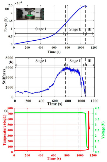
Figure 1.
Testing results for fully charged Li-ion batteries during indentation tests. (a) Force–time curve, (b) stiffness derivative of force versus time, and (c) voltage and temperature responses.
In this study, a soft ISC is defined as microscopic damage indicated by no change or a slow decline of the battery terminal voltage. A hard ISC is defined as a macroscopic fracture indicated by a rapid decline of the battery terminal voltage. In Figure 1c, the battery voltage started to decline, and the battery temperature started to rise at 972 s, which indicated that the ISC had already occurred under the microscopic damage stage. Initially, the battery voltage decreased slowly from 4.11 V at 972 s to 4.03 V at 1072 s, and the battery temperature increased slowly from 29.2 °C at 972 s to at 1072 s. These slow responses in voltage and temperature under the microscopic damage stage can be considered as a soft ISC. After this initial period, the battery voltage decreased rapidly from 4.03 V at 1072 s to 1 V at 1102 s, and the battery temperature increased rapidly from at 1124 s to at 1128 s. This indicated that the soft ISC occurring in Stage II had evolved to a hard ISC occurring in Stage III. It should be noted that the battery voltage and temperature showed no change at the initiation of Stage II, which can be explained as follows. Firstly, the damage was minor at first, and a small microscopic damaged area corresponded to a high ISC resistance. Secondly, the ISC took some time to develop during the incubation period [35,36].
3. Thermal Responses of Various ISC Conditions
3.1. Coupled Electrochemical-Electric-Thermal Model
An axisymmetric coupled electrochemical-electric-thermal model was established in COMSOL Multiphysics (version 5.2a) to further analyze the thermal response of Li-ion batteries under various ISC conditions. The positive electrode material was , the negative electrode material was , and electrolyte was . The governing equations and parameters of the model are presented in Table 2 and Table 3 [31,32,33]. In the governing equations, represents the reaction heat due to the reaction overpotential; is ohmic heat produced by charge transport in the electrodes and electrolyte; is reversible heat (entropy heat). All the parameters in the governing equations were adopted from [31,32,33] or estimated by a trial-and-error approach through simulation.
Table 2.
Governing equations of the axisymmetric model.
Table 3.
Physiochemical parameters used in the axisymmetric model.
The current passing through the ISC object was very large due to the small ISC resistance when the hard ISC took place inside the Li-ion battery. Therefore, the heat generation due to a large current was added into the model, and its heat generation rate was calculated by
where is the solid potential drop along the axial direction of the ISC object, is the ISC resistance, and is the volume of the ISC object inside the battery. This heat generation was added as a single heat source to the ISC object when the governing equations listed in Table 2 were solved.
As mentioned earlier, the damaged area and material properties of the short-circuit object are critical to determine the evolution from soft ISC to hard ISC under mechanical abusive conditions. Hence, the above coupled electrochemical-electric-thermal model considered the damaged area and the material properties of the short-circuit object under four different ISC types, namely negative–positive ISC, aluminum-negative ISC, copper-positive ISC, and aluminum–copper ISC. The following Equations (14)–(19) were used to calculate some parameters under the negative–positive ISC:
where L is the thickness, m is the mass of the ISC object, is the density, C is the specific heat, k is the thermal conductivity, is the thermal conductivity in the axial direction, is the thermal conductivity in the radial direction, S is the area of the ISC object, and is the radius of the area of the ISC object. These parameters under the other three ISC types were also calculated on the basis of Equations (14)–(19). Table 4 shows those parameters used in the simulation model.
Table 4.
Parameters of different internal short circuit (ISC) types.
Wang et al. compared the current flow path caused by nail penetration with that caused by an ISC [32]. They proposed that the un-shorted electrode layers supplied energy to the shorted electrode layers which formed a closed loop current path. The temperature rise in the shorted electrode layers was more serious than that in the un-shorted electrode layers, thus only the shorted electrode layers were considered in our axisymmetric coupled electrochemical-electric-thermal model. It should be noted that the ISC occurring in different layers of a Li-ion battery will change its surface temperature [37]. However, the main purpose of the simulation study was to investigate different thermal responses of shorted layers under different ISC conditions. Moreover, the model of only one shorted electrode layer was established at its radius of 3 cm to save computational time. The reasons for this simplification are as follows. Firstly, the numerical simulation of a detailed electrochemical-electric-thermal model represents a considerable challenge with high computation burden even for a single layer. Secondly, all electrode layers were fairly equivalent electrically and thermally. This simplification may underestimate electron transport to a certain extent, but the effect of this simplification should not be exaggerated, since the battery cell was found to work under secondary or tertiary current distribution [38]. As mentioned earlier, the effect of the material properties on the thermal response was also under our investigation. Hence, the surface heat transfer coefficient was set to . This boundary condition may have been slightly different from the real one because of the effects of these neglected layers on heat dissipation, but the effect of this setting was still within a reasonable range.
Spotnitz et al. summarized that the solid electrolyte interface (SEI) layer is decomposed at , and the other exothermic reactions occur at elevated temperatures () [28]. The heat produced by the SEI decomposition reaction is smaller than that produced by other exothermic reactions. Therefore, a Li-ion battery is considered a thermal runaway when the temperature reaches . The temperature for electrolyte decomposition is above [28], and only a part of the electrolyte decomposes during the short thermal runaway process. Moreover, the majority of heat is from a chain of side reactions during the thermal runaway process. It should be noted that some gaseous species will be produced during the thermal runaway process, such as gases from the evaporation of the electrolyte, oxygen produced by the decomposition of positive active material, etc. However, the simulation model only considered the heat produced by various chemical reactions including those reactions that produced gaseous species. The simulation was stopped when the aluminum’s temperature reached its melting point [33].
3.2. Effect of Various ISC Types on Thermal Responses
Under mechanical abusive conditions, different ISC types may occur inside the Li-ion batteries. The proposed model was used to investigate the thermal response of a Li-ion battery under various ISC types in the same damaged area (or intrinsic resistance) of the ISC object. As shown in Table 4, it can be seen that the resistance of the copper–aluminum ISC was much smaller than that of the aluminum-negative ISC. As a result, a fusing phenomenon could occur for the copper–aluminum ISC [33], which was not considered in the simulation investigated in this paper.
Figure 2 shows the thermal responses under different ISC types for the Li-ion battery at SOC = 0.2 and . Figure 2a shows the thermal response under the positive–negative ISC. The temperature rise in the positive and negative electrodes was almost the same, while that in the separator was much lower. For the case of the copper-positive ISC, the temperature rise in all three components was almost the same as depicted in Figure 2b. Although the ISC resistance of the copper-positive ISC was slightly lower than that of the positive–negative ISC (see Table 4), the temperature rise in the positive and negative electrodes under the copper–positive ISC was slightly lower than that under the positive–negative ISC because of the higher thermal conductivity of copper, as shown in Figure 2a,b, respectively. Therefore, the effect of the material properties of the ISC object on the thermal response could not be ignored. Figure 2c shows the thermal response under the aluminum-negative ISC. The temperature rise in the positive electrode and separator was almost the same, while that in the negative electrode was higher than that in the positive electrode and separator.
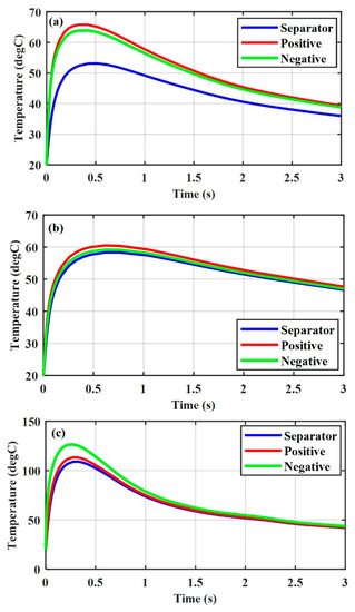
Figure 2.
Thermal responses of various ISC conditions for a Li-ion battery at SOC = 0.2 and . (a) Positive–negative, (b) copper-positive, and (c) aluminum-negative.
Comparing Figure 2a–c, it is obvious that the major effect on the thermal response was the ISC resistance at the same SOC and damaged area. We also found that the temperature rise under the aluminum-negative ISC was higher and faster than that under the positive–negative ISC and the copper-positive ISC, and the temperature rise in the negative electrode was higher than that in the positive electrode under the aluminum-negative ISC. Since a chain of side reactions occur inside the negative electrode at a lower temperature than inside the positive electrode, the aluminum-negative ISC is more dangerous than the other two ISC conditions. Active materials are attached on the current collector through glue. To improve the safety performance of a Li-ion battery, the adhesion strength can be increased to avoid the positive active materials at the electrode peeling from the aluminum current collector under mechanical abusive conditions, which could cause a direct contact between the aluminum current collector and the negative electrode. However, it is worth mentioning that an increase in the adhesion strength beyond a critical limit will impede electron transfer and consequently lower the electrochemical performance of a battery.
3.3. Effect of the Area of the ISC Object on Thermal Responses
Under different loading conditions, different deformation processes may damage different areas inside Li-ion batteries. The proposed model was also used to explore the effects of different damaged areas of ISC object on the thermal responses occurring inside Li-ion batteries. Usually, the positive–negative ISC is the most common ISC under mechanical abusive conditions. Furthermore, the simulation results in the previous section also indicated that the copper-positive ISC is less dangerous than the positive–negative ISC and aluminum-negative ISC. Thus, only the thermal responses under the positive–negative and aluminum-negative ISC conditions for the Li-ion battery with different damaged areas were studied in this section.
Figure 3 shows the thermal response of a Li-ion battery (SOC = 0.4) under the positive–negative ISC at different radii of the ISC object. The temperature in the negative and positive electrode with increased from the initial temperature of to almost in 0.96 s, while that in the negative and positive electrodes with increased from the initial temperature of to almost in 0.17 s. Figure 4 shows the thermal response of a Li-ion battery under the aluminum-negative ISC. The temperatures in the negative and positive electrodes with increased from the initial temperature of to almost and in 0.47 s, respectively, while the temperatures in the negative and positive electrodes with increased from the initial temperature of to almost in 0.1 s and in 0.13 s, respectively.
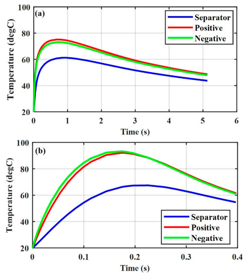
Figure 3.
Thermal response of various ISC areas, SOC = 0.4, positive–negative (a) , and (b) .
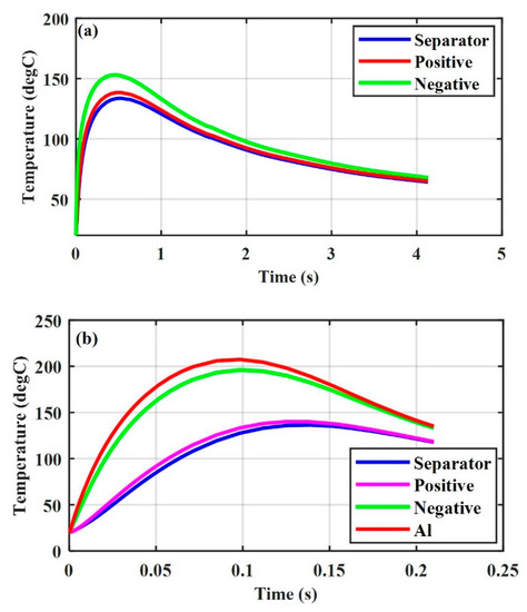
Figure 4.
Thermal response of various ISC areas, SOC = 0.4, aluminum-negative (a) , and (b) .
The simulation results indicated that the temperature of a Li-ion battery with a large damaged area will increase to a high value in a short time for the same radius of the ISC object, regardless of the ISC conditions. They also indicated that a Li-ion battery with a large damaged area () may not go into thermal runaway under the positive–negative ISC (see Figure 3b), and that with a small damaged area () may go into thermal runaway under the aluminum-negative ISC (see Figure 4a). This explains the experimental results under mechanical abusive conditions that a Li-ion battery may sometimes go into thermal runaway at a small compression displacement, while sometimes it may not go into thermal runaway at a large compression displacement [18].
3.4. Effect of a Li-ion Battery SOC on Thermal Responses
In real EV applications, Li-ion batteries may involve crash accidents at various SOCs. The proposed model was used to explore the thermal response of a Li-ion battery at different SOCs under the positive–negative and the aluminum-negative ISC conditions in the same large damaged area, namely, with .
Figure 5a shows the thermal response under positive–negative ISC at SOC = 0.2. The temperature in the negative and positive electrodes increased from the initial value of to almost in 0.12 s. Figure 5b shows the thermal response under the positive–negative ISC at SOC = 0.6. The temperature in the negative and positive electrodes increases from the initial value of to almost in 0.63 s.
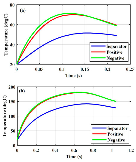
Figure 5.
Thermal response of various capacities, , positive–negative (a) SOC = 0.2, and (b) SOC = 0.6.
Comparing Figure 5a,b and Figure 2a, we could observe a more significant effect of the Li-ion battery SOC on its thermal response compared to the ISC resistance when the ISC resistance decreased to a substantially low level. This was supported by the experimental results in [18], namely, the ISC resistance value is very low in the indentation tests when a macroscopic fracture occurs inside the Li-ion battery. Despite serious damage caused by the macroscopic failure, the Li-ion battery did not experience thermal runaway because of its low SOCs.
Figure 6a shows the thermal response under the aluminum-negative ISC at SOC = 0.2. The temperature in the aluminum current collector and negative electrode increased from the initial temperature of to almost and in 0.07 s, respectively. Figure 6b shows the thermal response under the aluminum-negative ISC at SOC = 0.6. The temperature in the aluminum collector and negative electrode increased from the initial value of to almost and in 0.36 s, respectively, and the temperature of the aluminum collector did not reach its melting point corresponding to .
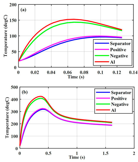
Figure 6.
Thermal response of various capacities, , aluminum-negative (a) SOC = 0.2, and (b) SOC = 0.6.
The above simulation results indicated that the Li-ion battery exhibited a temperature profile at low SOCs significantly different from that at high SOCs. This can be explained as follows. Firstly, a Li-ion battery at high SOCs has more stored energy and high voltage which can produce a high heat generation rate (see Equations (12) and (13)). Secondly, more stored energy means the ISC process will last longer and, correspondingly, more heat will be generated at the same large ISC current.
4. Validation
As mentioned earlier, the proposed coupled electrochemical-electric-thermal model was simplified to only take one electrode layer into account. A comparison of the temperature values between the experimental data obtained from a whole battery cell and those obtained from the simplified model is impossible. However, the thermal runaway of Li-ion batteries under mechanical abusive conditions is the focus in EV industries. Various mechanical loading conditions were performed on 18650 Li-ion batteries at the distinctive low SOC (e.g., SOC = 0.2) and high SOC (e.g., SOC = 0.6). The surface temperature of 18650 Li-ion batteries was measured to validate the simulation model by determining if the thermal runaway was triggered.
For the experiments of Li-ion batteries at the low SOC, the tests with three different loadings were performed, which corresponded to the compression test between two rigid plates, the indentation test with a rigid rod of 12 mm in radius, and the compression test with a hemispherical punch of 7 mm in radius. Their thermal responses were recorded as shown in Figure 7, where the images on the left side provides the maximum, minimum, and average battery temperatures at the onset of a macroscopic failure corresponding to the start, and the images on the right side provide the maximum, minimum, and average battery temperatures at the moment of its maximum value. For the case of a Li-ion battery compressed by two rigid plates, its temperature increased to (maximum temperature) after 300 s, as shown in Figure 7a on the right side. For the case of a Li-ion battery compressed by a rigid rod, its temperature increased to the maximum value after 100 s, as shown in Figure 7b on the right side. For the case of a Li-ion battery compressed by a hemispherical punch, it took about 200 s to reach the maximum temperature of , as shown in Figure 7c on the right side. These results indicate that the Li-ion batteries at low SOCs did not go into thermal runaway under the three loadings, which agrees with the simulation results of the Li-ion batteries at low SOCs under various ISC conditions, even with a large damaged area under the most dangerous case of the aluminum-negative ISC, as shown in Figure 2, Figure 5a and Figure 6a, respectively.
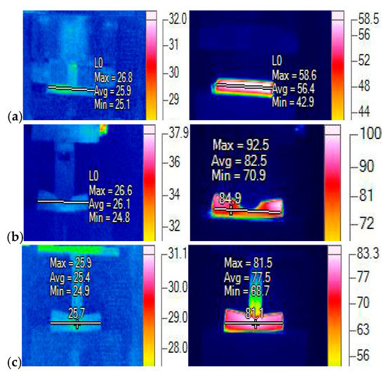
Figure 7.
Thermal responses under various loadings (unit: degC) at SOC = 0.2: (a) two rigid plates, (b) a rigid rod, and (c) a hemispherical punch.
For the experiments of Li-ion batteries, the test of the rigid rod loading was only performed as with a rigid rod at SOC = 0.6. The reasons are twofold. Firstly, the Li-ion batteries exhibited similar temperature responses under the three load conditions. Secondly, the Li-ion batteries at high SOCs could go into thermal runaway. Figure 8 shows the temperature profile of the Li-ion batteries at SOC = 0.6 compressed by a rigid rod; the left image provides the maximum, minimum, and average battery temperatures at the onset of a macroscopic failure corresponding to the start, and the right images provides the battery temperature after thermal runaway. The Li-ion battery at SOC = 0.6 compressed by a rigid rod went into thermal runaway only after 10 s, and a lot of smoke was generated (see Figure 8 on the right side). It should be noted that the generation of a lot of smoke indicates the thermal runaway was triggered. Hence, the battery surface temperature was far higher than . The temperature measurement was obviously affected by the produced smoke, and the measured value () in Figure 8 is the smoke temperature instead of the battery surface temperature. This experimental result also agrees with the simulation results indicating that the Li-ion batteries at SOC = 0.6 under various ISC conditions went into thermal runway, as depicted in Figure 5b and Figure 6b.
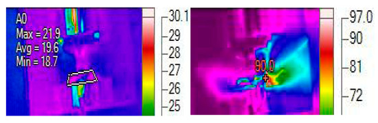
Figure 8.
Thermal response of the battery compressed by a rigid rod (unit: degC) at SOC = 0.6.
5. Conclusions
In this study, we took a hybrid experimental–numerical approach to investigate various ISC conditions for Li-ion batteries under mechanical abusive conditions. The experimental results indicate that the deformation process of a Li-ion battery can be described by a densification process, a soft ISC process, and a hard ISC process. Mathematically, an axisymmetric coupled electrochemical-electric-thermal model was established in COMSOL Multiphysics (version 5.2a) to further reveal the thermal responses of Li-ion batteries under various ISC conditions by considering the material properties and the damaged area of the ISC object. The following conclusions were obtained based on the experimental and simulation results.
- Under mechanical abusive conditions, a soft ISC occurs before the peak force and will evolve into a hard ISC as deformation continues.
- The material property of the ISC object has a strong impact on the thermal response of a Li-ion battery, which cannot be ignored.
- A Li-ion battery at high SOCs can easily trigger thermal runaway under various ISC conditions, and more serious accidents will be caused compared with those caused by a Li-ion battery at low SOCs.
- The effect of a Li-ion battery SOC on its thermal response is more significant than the effect caused by the ISC resistance, especially when the ISC resistance decreases to a substantially low level.
- A Li-ion battery with a small damaged area may go into thermal runaway under the aluminum-negative ISC, while that with a large damaged area at low SOCs may not go into thermal runaway under the positive-negative ISC. Hence, an appropriate increase in adhesion strength between the aluminum current collector and the positive electrode can improve battery safety under mechanical abusive conditions, while still maintaining good electrochemical performance.
Author Contributions
All authors contributed to this work by collaboration. S.Y. wrote this paper, and all authors approved it for publication.
Funding
This research was funded by Beijing Science and Technology Program (grant number Z181100004518005). Check carefully that the details given are accurate and use the standard spelling of funding agency names at https://search.crossref.org/funding, any errors may affect your future funding.
Acknowledgments
The authors would like to sincerely acknowledge Rui Xiong and his Advanced Energy Storage and Application (AESA) Group at Beijing Institute of Technology for providing the battery experiment support.
Conflicts of Interest
The authors declare no conflict of interest.
Nomenclature
| Symbols | |
| Specific active surface area for an electrode | |
| c | Li concentration in phase |
| C | Specific heat capacity |
| D | Diffusion coefficient of Li species |
| F | Faraday’s constant |
| Mean molar activity coefficient of the electrolyte | |
| h | Heat transfer coefficient |
| Exchange current density | |
| j | Volumetric reaction current |
| k | Rate constant for an electrode reaction |
| q | Volumetric heat generation |
| R | Universal gas constant |
| T | Temperature |
| t | Time |
| Transference number of Li-ion | |
| U | Equilibrium potential of an electrode reaction |
| Transfer coefficient | |
| Surface overpotential of an electrode reaction | |
| Ionic conductivity of electrolyte | |
| Diffusional conductivity | |
| Electrical potential in a phase | |
| Plastic stress | |
| Plastic strain | |
| Maximum concentration of Li in solid phase | |
| Superscripts | |
| eff | Effective |
| Li | Li species |
| Subscripts | |
| 0 | Initial value |
| a/neg | Negative electrode |
| c/pos | Positive electrode |
| e | Electrolyte phase |
| s | Solid phase |
| S | Shorted area |
References
- Ko, S.T.; Lee, J.H.; Ahn, J.H.; Lee, B.K. Innovative modeling approach for Li-ion battery packs considering intrinsic cell unbalances and packaging elements. Energies 2019, 12, 356. [Google Scholar] [CrossRef]
- Xiong, R.; Tian, J.P.; Shen, W.X.; Sun, F.C. A novel fractional order model for state of charge estimation in lithium ion batteries. IEEE Trans. Veh. Technol. 2018. [Google Scholar] [CrossRef]
- Pang, H.; Zhang, F.Q. Experimental data-driven parameter identification and state of charge estimation for a Li-ion battery equivalent circuit model. Energies 2018, 11, 1033. [Google Scholar] [CrossRef]
- Liu, B.H.; Jia, Y.K.; Li, J.; Yin, S.; Yuan, C.H.; Hu, Z.H.; Wang, L.B.; Li, Y.X.; Xu, J. Safety issues caused by internal short circuits in lithium-ion batteries. J. Mater. Chem. A 2018, 6, 21475–21484. [Google Scholar] [CrossRef]
- Chen, C.; Xiong, R.; Shen, W.X. A lithium-ion battery-in-the-loop approach to test and validate multiscale dual H infinity filters for state-of-charge and capacity estimation. IEEE Trans. Power Electr. 2018, 33, 332–342. [Google Scholar] [CrossRef]
- Jia, Y.K.; Yin, S.; Liu, B.H.; Zhao, H.; Yu, H.L.; Li, J.; Xu, J. Unlocking the coupling mechanical-electrochemical behavior of lithium-ion battery upon dynamic mechanical loading. Energy 2019, 166, 951–960. [Google Scholar] [CrossRef]
- Jansen, A.N.; Kahaian, A.J.; Kepler, K.D.; Nelson, P.A.; Amine, K.; Dees, D.W.; Vissers, D.R.; Thackeray, M.M. Development of a high-power lithium-ion battery. J. Power Sources 1999, 81, 902–905. [Google Scholar] [CrossRef]
- Lee, K.J.; Smith, K.; Pesaran, A.; Kim, G.H. Three dimensional thermal-, electrical-, and electrochemical-coupled model for cylindrical wound large format lithium-ion batteries. J. Power Source 2013, 241, 20–32. [Google Scholar] [CrossRef]
- Feng, X.N.; Lu, L.G.; Ouyang, M.G.; Li, J.Q.; He, X.M. A 3D thermal runaway propagation model for a large format lithium-ion battery module. Energy 2016, 115, 194–208. [Google Scholar] [CrossRef]
- Larsson, F.; Andersson, P.; Blomqvist, P.; Loren, A.; Mellander, B.E. Characteristics of lithium-ion batteries during fire tests. J. Power Sources 2014, 271, 414–420. [Google Scholar] [CrossRef]
- Larsson, F.; Mellander, B. Abusive by external heating, overcharge and short circuiting of commercial lithium-ion battery cells. J. Electrochem. Soc. 2014, 161, A1611–A1617. [Google Scholar] [CrossRef]
- Ping, P.; Wang, Q.S.; Huang, P.F.; Li, K.; Sun, J.H.; Kong, D.P.; Chen, C.H. Study of the fire behavior of high-energy lithium-ion batteries with full-scale burning test. J. Power Sources 2015, 285, 80–89. [Google Scholar] [CrossRef]
- Feng, X.N.; Fang, M.; He, X.M.; Ouyang, M.G.; Lu, L.G.; Wang, H.; Zhang, M.X. Thermal runaway features of large format prismatic lithium ion battery using extended volume accelerating rate calorimetry. J. Power Sources 2014, 255, 294–301. [Google Scholar] [CrossRef]
- Kriston, A.; Pfrang, A.; Döring, H.; Fritsch, B.; Ruiz, V.; Adanouj, I.; Kosmidou, T.; Ungeheuer, J.; Boon-Brett, L. External short circuit performance of Graphite-LiNi1/3Co1/3Mn1/3O2 and Graphite-LiNi0.8Co0.15Al0.05O2 cells at different external resistances. J. Power Sources 2017, 361, 170–181. [Google Scholar] [CrossRef]
- Ren, D.S.; Feng, X.N.; Lu, L.G.; Ouyang, M.G.; Zheng, S.Q.; Li, J.Q.; He, X.M. An electrochemical-thermal coupled overcharge-to-thermal-runaway model for lithium ion battery. J. Power Sources 2017, 364, 328–340. [Google Scholar] [CrossRef]
- Guo, R.; Lu, L.G.; Ouyang, M.; Feng, X.N. Mechanism of the entire overdischarge process and overdischarge-induced internal short circuit in lithium-ion batteries. Sci. Rep. 2016, 6, 30248. [Google Scholar] [CrossRef]
- Wang, W.W.; Yang, S.; Lin, C. Clay-like mechanical properties for the jellyroll of cylindrical Lithium-ion cells. Appl. Energy 2017, 196, 249–258. [Google Scholar] [CrossRef]
- Wang, W.W.; Yang, S.; Lin, C.; Li, Y.D. State of charge dependent constitutive model of the jellyroll of cylindrical Lithium-ion cells. IEEE Access 2018, 6, 26358–26366. [Google Scholar] [CrossRef]
- Sahraei, E.; Bosco, E.; Dixon, B.; Lai, B. Microscale failure mechanisms leading to internal short circuit in Li-ion batteries under comples loading scenarios. J. Power Sources 2016, 319, 56–65. [Google Scholar] [CrossRef]
- Sahraei, E.; Kahn, M.; Meier, J.; Wierzbicki, T. Modelling of cracks developed in lithium-ion cells under mechanical loading. RSC Adv. 2015, 5, 80369. [Google Scholar] [CrossRef]
- Zhu, J.E.; Zhang, X.W.; Sahraei, E.; Wierzbicki, T. Deformation and failure mechanisms of 18650 battery cells under axial compression. J. Power Sources 2016, 336, 332–340. [Google Scholar] [CrossRef]
- Kisters, T.; Sahraei, E.; Wierzbicki, T. Dynamic impact tests on lithium-ion cells. Int. J. Impact Eng. 2017, 108, 205–216. [Google Scholar] [CrossRef]
- Kermani, G.; Sahraei, E. Dynamic impact response of lithium-ion batteries. Constitutive properties and failure model. RSC Adv. 2019, 9, 2464. [Google Scholar] [CrossRef]
- Kermani, G.; Sahraei, E. Review: Characterization and Modeling of the Mechanical Properties of Lithium-ion Batteries. Energies 2017, 10, 1730. [Google Scholar] [CrossRef]
- Zhang, M.; Du, J.; Liu, L.; Stefanopoulou, A.; Siegel, J.; Lu, L.; He, X.; Xie, X.; Ouyang, M. Internal short circuit Trigger Method for Lithium-ion Battery Based on Shape Memory Alloy. J. Electrochem. Soc. 2017, 161, A3038–A3044. [Google Scholar] [CrossRef]
- Maleki, H.; Howard, J.N. Internal short circuit in Li-ion cells. J. Power Sources 2009, 191, 568–574. [Google Scholar] [CrossRef]
- Hatchard, T.; MacNeil, D.; Basu, A.; Dahn, J. Thermal model of cylindrical and prismatic lithium-ion cells. J. Electrochem. Soc. 2001, 148, A755–A761. [Google Scholar] [CrossRef]
- Spotnitz, R.; Franklin, J. Abusive behavior of high-power, lithium-ion cells. J. Power Sources 2003, 113, 81–100. [Google Scholar] [CrossRef]
- Spotnitz, R.M.; Weaver, J.; Yeduvaka, G.; Doughty, D.; Roth, E. Simulation of abusive tolerance of lithium-ion battery packs. J. Power Sources 2007, 163, 1080–1086. [Google Scholar] [CrossRef]
- Kim, G.H.; Pesaran, A.; Spotnitz, R. A three-dimensional thermal abusive model for lithium-ion cells. J. Power Sources 2007, 170, 476–489. [Google Scholar] [CrossRef]
- Zhao, W.; Luo, G.; Wang, C.Y. Modeling Nail Penetration Process in Large-Format Li-Ion Cells. J. Electrochem. Soc. 2015, 162, A207–A217. [Google Scholar] [CrossRef]
- Zhao, W.; Luo, G.; Wang, C.Y. Modeling Internal Shorting Process in Large-Format Li-Ion Cells. J. Electrochem. Soc. 2015, 162, A1352–A1364. [Google Scholar] [CrossRef]
- Zhang, M.X.; Liu, L.S.; Stefanopoulou, A.; Siegel, J.; Lu, L.G.; He, X.M.; Ouyang, M. Fusing Phenomenon of Lithium-Ion Battery Internal Short Circuit. J. Electrochem. Soc. 2017, 164, A2738–A2745. [Google Scholar] [CrossRef]
- Zhu, J.E.; Zhang, X.W.; Luo, H.L.; Sahraei, E. Investigation of the deformation mechanisms of the lithium-ion battery components using in-situ micro tests. Appl. Energy 2018, 224, 251–266. [Google Scholar] [CrossRef]
- Doughty, D.H.; Pesaran, A. Vehicle Battery Safety Roadmap Guidance; Subcontract Rep No. NREL/SR-5400-54404; National Renewable Energy Laboratory: Golden, CO, USA, 2012.
- Barnett, B. Technologies for detection and intervention of Internal short circuts in Li-ion batteries. Presented at the 5th Annual Knowledge Foundation Conference on Battery Safety, Washington, DC, USA, 13–14 November 2014. [Google Scholar]
- Finegan, D.P.; Darst, J.; Walker, W.; Li, Q.; Yang, C.; Jervis, R.; Heenan, T.M.; Hack, J.; Thomas, J.C.; Rack, A.; et al. Modeling and experiments to identify high-risk failure scenarios for testing the safety of lithium-ion cells. J. Power Sources 2019, 417, 29–41. [Google Scholar] [CrossRef]
- Tommy, G.Z.; Marten, B.; Goran, L. Investigation of Short-Circuit Scenarios in a Lithium-Ion Battery Cell. J. Electrochem. Soc. 2012, 159, A848–A859. [Google Scholar]
© 2019 by the authors. Licensee MDPI, Basel, Switzerland. This article is an open access article distributed under the terms and conditions of the Creative Commons Attribution (CC BY) license (http://creativecommons.org/licenses/by/4.0/).