Abstract
This paper presents a fuzzy logic based algorithm developed to bring smart functionality to an ordinary PV-battery system in order to maintain the grid voltage stability of the 22 kV distribution system in Thailand. This research focuses on minimizing grid voltage fluctuations by converting a typical PV system into a smart PV-battery system (SPVs-BSS). A SPVs-BSS will be able to control the electrical power from a PV system to maintain the grid voltage in case of unexpected events or emergencies. Grid support functions such as a variable reactive power control and active power control will be discussed, leading to strategies for charging and discharging the battery system in response to the status of grid voltage. Fuzzy Logic was used to develop this control algorithm, which is named the Voltage Stability Fuzzy Logic Algorithm (VSFL Algorithm). The methodology of this research consists of three parts. First, testing the grid inverter operated on grid support functions. Second, the VSFL algorithm was developed to manage both the grid inverter and the battery system. Third, a SPVs-BSS equipped with the VSFL algorithm was simulated by using DIgsilent PowerFactory software. Results showed that the SPVs-BSS equipped with the VSFL Algorithm successfully maintained grid voltage in target range.
1. Introduction
Nowadays the use of renewable energy in Thailand has grown significantly due to electrical demand and electrical market competition. Solar energy has great potential in Thailand. Photovoltaic (PV) power generation in Thailand is growing at a rapid rate, in part because in 2007 the government created an incentive in the form of an Adder (8 baht/kWh) for PV power plants. That Adder was followed by a Feed-In Tariff (6.5 baht/kWh) [1]. The government is providing incentives not only large scale solar power plants but also for small scale PV rooftop systems of 1–10 kW capacity, which are spreading all over Thailand. In 2018, the total capacity of PV systems in Thailand is greater than 3 GW [2] as shown in Figure 1. PV systems can generally be divided into two groups: ground installations and rooftop units. The systems are connected to the grid at distribution level (22 kV or Lower) or transmission level (115 kV) [3]. Normally traditional distribution networks are designed with one-way power flow from a point of high voltage (or medium voltage) to a point of low voltage but in the new concept of modernized distribution networks (Smart Grids), the voltage at the end of the load can be greater than the feeder supply voltage [4,5,6,7,8,9].
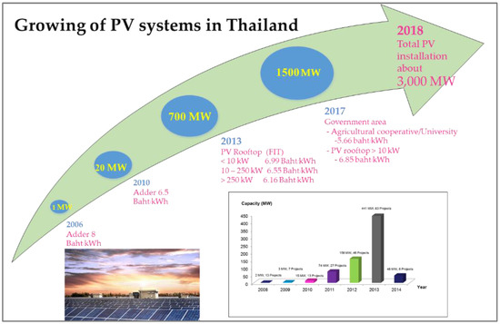
Figure 1.
PV system installation in Thailand.
This characteristic of the feeder is due to the impact of grid connected PV systems. The increasing number of PV systems connected to Low Voltage Distribution Systems (LVDS) has some negative impacts on LVDS such as lower power quality (Voltage variations, frequency variations, harmonics distortion, etc.) and less power control (Power factor, Power fluctuation) [10,11,12,13,14,15,16]. If the PV generation is greater than the local demand at the point of common coupling (PCC), the excess power from PV inverters may produce reverse power flow in the feeder, which would have a negative impact on the LVDS. Grid voltage rise is the major problem when electricity is fed back to the grid by PV systems. According to the interconnection code of PEA, the acceptable range of voltage in the distribution is ±10% of nominal voltage [17]. 80% of PV systems are connected to the LVDS. Voltage rise is major problem of this extensive integration of PV systems. Many countries have experienced problems from having a high share of PV systems integrated to LVDS. The problem has occurred notably in those countries, which promoted electricity production from renewable sources and then enhanced their installation capacity to Giga-Watt level for examples, Germany, Australia, Italy, Spain Switzerland, Belgium, China and Japan [18,19,20,21,22,23,24]. Without proper, prompt solutions for these problems, electricity production from renewable sources will not succeed. In light of that problem, the current study seeks to mitigate voltage fluctuation caused by high PV system penetration by converting a typical PV system into a smart PV system. The concept of a smart PV system in this research refers to a battery storage system being integrated with a PV system and improvement of the inverter’s ability to maintain grid voltage stability [25,26]. Having a control algorithm also important for a smart PV system and therefore this research will develop a control algorithm using Fuzzy Logic. Fuzzy logic is an effort to represent the human reasoning methods. It can control a complicated system that would be hard or problematic to control by any others method. Fuzzy control algorithm is popularly used to apply throughout many aspects for modern electrical system. The purpose of the algorithm development in this research is to maintain the distribution voltage into the desired range (0.96 p.u.–1.06 p.u.). The typical 22 kV distribution system integrated with a typical 8 MW PV power plant in the northeast of Thailand also has the problem on voltage rise when a high amount of active power production from the PV system fed to the distribution system. This case will be studied in order to find the robust solution for maintaining the distribution voltage into the target range by controlling two entities, the battery power management and inverter power management. The operation of a smart PV system equipped with a control algorithm will be studied for distribution voltage stability. A smart PV system empowered with a proper algorithm is a solution to reach the Thailand target of 6000 MW PV capacity installation in 2036.
2. Research Methodology
The research methodology in this research can be divided into three steps. First, the grid inverter was tested in electrical laboratory at the School of Renewable Energy Technology (SERT) at Naresuan University. The grid inverter is tested for its grid support functions (active and reactive power control), while the BESS is tested for its charge/discharge impacts. The results of these tests show that both components have the ability to affect grid voltage stability in the various expected ways and have the potential to be used and managed in combination to maintain overall grid voltage stability. Next an algorithm, called the VSFL Algorithm, is developed to manage these various capabilities of the grid inverter and battery storage system of a smart PV system in combination, using fuzzy logic. Finally, the VSFL Algorithm is tested by using DIgsilent PowerFactory software (research license of Naresuan University, School of Renewable Energy Technology, Thailand) to run two simulations. The first test simulates a typical PV system connected to a 22 kV distribution system and the second test simulates a smart PV system operating with the VSFL Algorithm, also connected to a 22 kV distribution system.
The aim of running the two simulations is to confirm whether the algorithm, by managing the added a BESS, will indeed be able to maintain grid voltage stability. All these steps of the research methodology are shown in Figure 2.
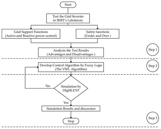
Figure 2.
Research methodology.
3. Test the Grid Inverter for Grid Support Functions
Grid inverter capability was tested in electrical laboratory on grid support functions and safety function to understand the process of maintaining the distribution voltage into the acceptable range. The main components of SERT’s electrical laboratory consisted of, regenerative grid simulator, battery storage, RLC electronic load and measurement system as shown in Figure 3.
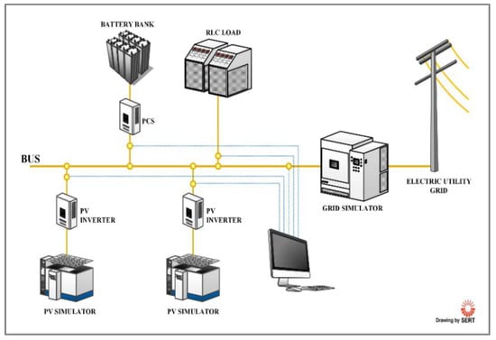
Figure 3.
SERT Electrical Laboratory.
The electrical laboratory can simulate the parameters in order to simulate real grid environments and conditions. The regenerative grid simulator can create a need for rigorous regulation testing to standard such IEEE 1547, IEC 610003-15 and IEC 62116. The grid simulator allows users to vary relevant parameters such as phase angle, voltage amplitude, voltage drops in either single or three phase modes. Moreover, unbalanced three phase conditions can easily be simulated. The function of grid support of inverter will be tested and simulated in this laboratory.
Voltage Rise Caused by PV System
As described in the introduction, main problem of high penetration PV system integrated within the distribution system is voltage rise, it may over than over limit of the country requirement. For clearly understand a simplified two-bus system integrated with a PV system is presented in Figure 4.
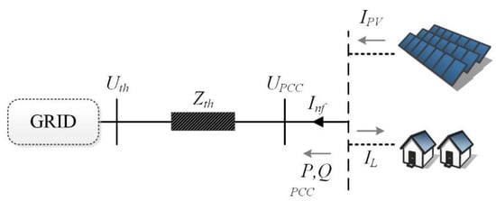
Figure 4.
Thevenin equivalent of a typical PV system integrated to distribution system.
Consideration, and are the Thevenin impedance and the Thevenin Voltage. Where, and are the net feed current and net apparent power, respectively. is the PV feed in current and is the load current. is real power and is reactive power. is the voltage at point of common coupling (PCC). The net feed-in current () can be calculated as Equation (1) [27].
The voltage at PCC can be calculated as Equation (3).
Suppose that the can be written as Equation (4). Where, is resistance and is reactance.
where and are the real and imaginary parts of , respectively. The voltage magnitude can be calculated as Equation (6).
Therefore, the approximate voltage magnitude at PCC can be simplified as the Equation (7) [27].
4. Test Results of Grid Inverter
Grid support functions of grid inverter in this research was mainly focused on reactive and active power control depending on grid voltage as follow.
4.1. Reactive Power Control
Reactive power control is a commonly chosen tool for maintaining the distribution voltage within an acceptable range. When the distribution voltage is in a dangerous range (i.e., above or below the acceptable range of 0.9 Vn–1.10 Vn), the grid inverter and battery inverter have the ability to activate reactive power (either lagging or leading) to manipulate the grid voltage. Activating lagging reactive power will lower critically high grid voltage and activating leading reactive power will raise critically low grid voltage [28,29]. The ability to control reactive power for the purpose of stabilizing voltage is an important resource and tool for network operators. Consequently, Thailand’s Provincial Electricity Authority’s (PEA) Power Network System Interconnection Code of 2016 (PEA grid code 2016) requires all PV systems to be able to supply not only active power but also reactive power to the distribution system. Specifically, the PEA grid code 2016 mandates the reactive power capabilities of PV system inverters depending on their electrical capacity. Inverters with a capacity of 500 kW or higher are required to be able to adjust their power factor (PF) between 0.90 lagging and 0.90 leading, while inverters with a capacity lower than 500 kW are required to be able to adjust their PF between 0.95 lagging and 0.95 leading. Given the PEA grid code 2016, the reactive power capabilities of grid inverters should be a dependable resource to network operators for maintaining the grid voltage within the acceptable range. For this reason, ability of grid inverter and battery pcs were tested in SERT’s electrical laboratory according to reactive power control. The test results of the grid inverter and battery pcs on grid support function, reactive power control for maintaining the grid voltage are described below. The test results of reactive power control of grid inverter and battery PCS can be seen in Figure 5.
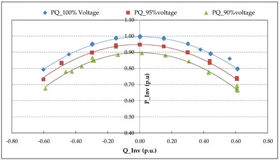
Figure 5.
Relationship between active power (P) and reactive power (Q) of grid inverter operation.
Figure 6 shows the operation of grid inverter on grid support function, when grid voltage was higher than normal voltage so bus voltage can be decreased by absorbing the reactive power. On the other hand, grid inverter and battery pcs provides the reactive power support in case of grid voltage is lower than the normal voltage (1 p.u. of Vn is 350 V) so the grid voltage can be increased. According to the Beginning of the test (Figure 6), grid voltage setting at the grid simulator was lower than Vn at 0.90 Vn, during this situation the grid inverter operated at the PF 0.90 lagging to inject reactive power for supporting and increasing the grid voltage to 0.95 Vn. At the middle of the test, the setting voltage same as nominal grid voltage, the grid inverter operated at the PF 1. At the end of the test, the grid voltage setting is higher than normal voltage at 1.09 Vn, this situation the inverter operates at PF 0.90 leading to absorb the reactive power. The behavior of the grid inverter during the test was the reactive power control depend on the grid voltage or a variable reactive power depending on the voltage Q (U) in PEA grid code 2016.
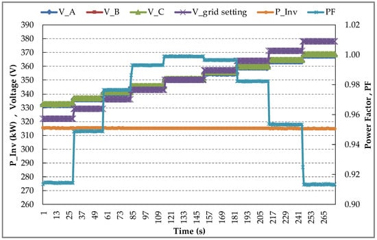
Figure 6.
To maintain the grid voltage by reactive power control of grid inverter. (V_A is grid voltage phase A, V_B is grid voltage phase B, V_C is grid voltage phase C, V_grid setting is voltage setting by grid simulator, P_Inv is power output of grid inverter and PF is power factor of inverter).
4.2. Active Power Control
Active power control depending on the grid voltage in this research, aims to control the power output of the grid inverter and battery PCS for maintaining gird voltage at the acceptable range of PEA requirements. The active power control is necessary for the grid operator in case of emergency such as grid voltage is higher than upper limit because of over active power fed to the grid. This case the grid inverter can automatically decrease the active power for keeping the grid voltage stability. According to PEA grid code 2016, the grid inverter requires to limit the active power from 1 p.u. to 0 p.u. with responsible time less than one minute per steps.
5. Algorithm Development
According to the problem of voltage rise due to over active power, which is produced from the PV system as mention in the introduction. After testing of grid connected inverter and analyzing advantages and disadvantages of both components, an algorithm operating with fuzzy logic, the VSFL Algorithm, was developed to greatly increase control of the grid inverter and battery storage system for grid voltage stability. Fuzzy Logic method (FLm), a flexible and powerful tool with much potential for electrical power systems, is similar to human beings’ feelings and decision making processes. Fuzzy Logic control is a range to point or range-to-range control. Fuzzy Logic techniques is applied throughout many purposes [30,31,32]. Fuzzy logic implementations involve three essential steps: the first is Fuzzification, this process to convert crisp values to fuzzy data using membership functions (MF), second is Inference process, to process MF within sets of rules or laws to develop the fuzzy output and third is Defuzzification [33], to determine the correct output. The output of FLm is derived from Fuzzifications of both input and output using the associated membership functions. The steps of algorithm are follows, Fuzzifications, Inference process and Defuzzification as shown in Figure 7.
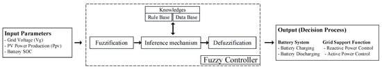
Figure 7.
Fuzzy controller for the VSFL Algorithm.
The VSFL Algorithm is mainly focusing on maintaining the grid voltage of 22 kV distribution system into the target range (1.06 p.u.–0.96 p.u. of voltage). In the present situation, the distribution voltage is not in the desired range 0.96 p.u. (21.12 kV) to 1.06 p.u. (23.32 kV) when high amount of active power is fed to the distribution system or high load power consumption occur. A smart PV-battery system equipped with the VSFC Algorithm will operate for maintaining the grid voltage into the target range or close to the normal voltage (22 kV, 1.0 p.u.) as follow two steps, the first is battery power management and second is grid inverter power management. The VSFL Algorithm enables to maintain the grid voltage as shown in Figure 8.
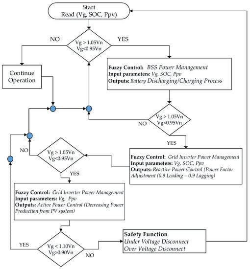
Figure 8.
The VSFL Algorithm for grid voltage stability.
The control sequence of the VSFL Algorithm starts with battery power management, later on the electrical power from a smart PV system will be managed by the grid inverter, in case of voltage is not in target range as follow.
5.1. Battery Storage System Energy Management
BSSEM is very important for a grid modernization to provide many of pragmatisms such as load leveling, peak shaving, peak shifting and frequency and voltage stability control. BSSEM in this research mainly focused on grid voltage stability in 22 kV distribution system. In case of grid voltage at PCC is out of target ranges (0.96 p.u.–1.06 p.u. for this research), a smart PV system ordered the battery storage system (BSS) to maintain the grid voltage into acceptable ranges by charge and discharge electrical power of BSS. When the grid voltage is over, a smart PV system enabled BSS to absorb an electrical power by charging to the BSS. The objective function of this process to decrease the active power in the distribution system result to decrease the distribution voltage. The VSFC Algorithm enables to control the BSS in a smart PV system by charging and discharging strategies.
5.2. Grid Inverter Power Management
In case of the gird voltage value is out of the target range (0.96 p.u.–1.06 p.u. for this research) and battery storage system is not able to operate when battery already full capacity or battery already reach the minimum SOC. If the grid voltage value still out of the target range, the grid inverter of a smart PV system will operate on grid support functions, reactive power control and active power control to maintain the grid voltage stability of distribution system. Generally, if the grid voltage is over than over limit of target range, grid inverter is able to absorb the reactive power in the distribution system, purpose to decrease the grid voltage. On the other hand, in case of under voltage, the grid inverter will operate to inject the reactive power to the grid, purpose to increase the grid voltage in distribution system. In the worst case, even the grid inverter operates on reactive power control but the grid voltage value is still out of range.
5.3. Fuzzifications of Input and Output Parameters
Fuzzification process is to convert crisp values to fuzzy data, each input and output parameters are converted to membership function (MF) as follow.
Figure 9a illustrates the membership function of PV power production (Ppv) which is classified into ranges of MF; low, medium and high based on power production in percentage of capacity at any instance of time as described in Table 1.
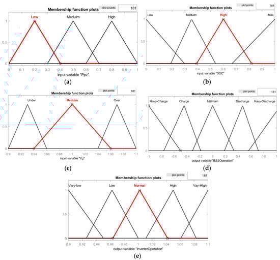
Figure 9.
Membership function of inputs and outputs parameters. (a) is the membership function of PV power production; (b) is the membership function of Battery state of charge; (c) is the membership function of grid voltage at point of common coupling; (d) is membership function of battery storage system operation; (e) is membership function of grid inverter operation.

Table 1.
Range and degree of membership function of PV power output.
Figure 9b illustrates the membership function of battery state of charge (SOC) which is classified into ranges of MF; low, medium, high and max based on energy contain in the battery in percentage at any instance of time as described in Table 2.
Table 2.
Range and degree of membership function of battery state of charge.
Figure 9c illustrates the membership function of distribution voltage (Vg) at the point of common coupling (PCC) which is classified in to ranges of MF, under, medium and over in power units (p.u.) at any instance of time as described in Table 3.
Table 3.
Range and degree of membership function of distribution voltage at PCC.
Figure 9d illustrates the membership function of battery power management, which is classified into ranges of MF; heavy-charge, charge, maintain, discharge and heavy-discharge at any instance of time as described in Table 4.
Table 4.
Range and degree of membership function of battery power management.
Figure 9e illustrates the membership function grid inverter power management which is classified into ranges of MF; very-low, low, normal, high and vary-high at any instance of time as described in Table 5.
Table 5.
Range and degree of membership function of inverter power management.
5.4. Fuzzy Inference
The fuzzy inference is the process that combination of membership functions with the rule base, knowledge and control rules for refining the fuzzy output. The control rules of fuzzy inference were considered as the knowledge of expert persons. A IF-THEN rule is applied to described linguistic variants and fuzzy sets to meditate a fuzzy output. The VSFL Algorithm fuzzy inference consisted of battery power management and grid inverter power management as shown in Table 6 and Table 7.
Table 6.
Fuzzy inference of inverter power management for grid voltage stability.
Table 7.
Fuzzy inference of battery power management for grid voltage stability.
5.5. Defuzzification
The Defuzzification process converts fuzzy output to a crisp output. The crisp output can be number or digital output, which is used to enable for controlling the equipment. This research used the Centroid Method as showed in Equation (8).
When is the decision output for batter power management and inverter power management. is the degree of output membership function. Z is the output variable of membership function.
The outputs by Defuzzification process of the VSFL Algorithm can be separated into two entities; the first is battery power management and second is inverter power management as shown in Figure 10.
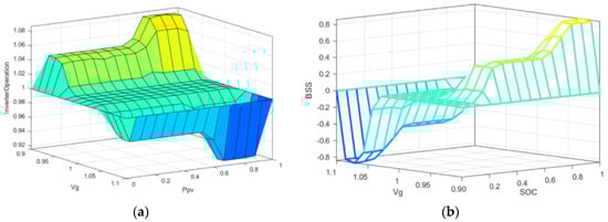
Figure 10.
Defuzzification of the VSFL Algorithm. ((a) Is Defuzzification output of inverter power management and (b) is Defuzzification output of battery power management).
6. Simulation of 22 kV Distribution with a Smart PV System
To verify the operation of a smart PV system equipped with the VSFL Algorithm for grid voltage stability, the typical 22 kV distribution system in Thailand was modified to the 22 kV distribution test system connected with a smart PV system. The simulation can be divided into two parts; the first is 22 kV distribution test system connected with an 8 MW typical PV system and second is a distribution test system connected with a smart PV system equipped with the VSFL Algorithm. The voltage profiles of main busbar (MBB) will be simulated by DIgSILENT PowerFactory software V. 15.1 (research license of Naresuan University, School of Renewable Energy Technology, Thailand). The modified 10 busbars of 22 kV distribution test system in this research is presented in Figure 11.
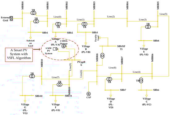
Figure 11.
Modified 22 kV distribution test system.
The 22 kV distribution test system was modified from a distribution system that is already use in the northeast of Thailand. The feeder which is connected with an 8 MW typical PV system will be used for the simulation. The detail of main components within the 22 kV distribution test system which is important for the simulation as shown in Table 8.
Table 8.
Main components within 22 kV distribution test system.
The different between typical PV system and a smart PV system in this research is that a smart PV system consists of battery storage system (3 MW peak power and 2 MW h of energy capacity) equipped with the VSFL Algorithm as shown in Figure 12.
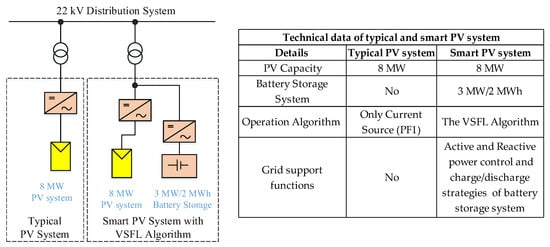
Figure 12.
The difference of a typical PV system and a smart PV system.
Case Studies of the Simulation
The case studies were divided into nine cases (case 1 to case 9). The difference of each case is that, the load capacity is vary from maximum at case 1 (6 MW) to minimum at case 9 (1.2 MW) in the distribution system as shown in Table 9.
Table 9.
Cases studies of the simulation.
7. Results and Discussion
Here are the results for the two test simulations that were run, the first simulating a typical PV system connected to a 22 kV distribution and the second simulating a smart PV system operating with the VSFL Algorithm, also connected to a 22 kV distribution system.
7.1. Simulation of a Typical PV System Connected to a 22 kV Distribution
Generally, the voltage in the profile of a distribution system decreases the further the voltage source is from the location of the load. This voltage drop occurs in the distribution system because the electric current travels though passive elements (such as wires, conductors, the load itself, etc.) that create resistance, dragging on the voltage and decreasing it. Figure 13 shows voltage profiles for ten cases resulting from the first simulation (i.e., typical PV, no VSFL Algorithm). All these profiles in Figure 13 are for the distribution system running without PV power production, and the 10 cases represent variations in load from minimum (case 10) to maximum (case 2).
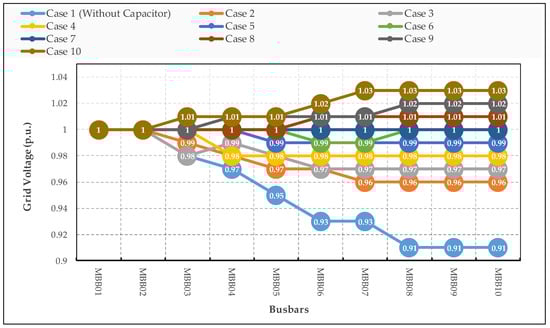
Figure 13.
Voltage profile of the distribution system without PV power production.
Figure 13 shows the voltage profile in the typical distribution system. One can clearly see that in Case 1 the voltage dropped in proportion to increasing distance from the substation to each more distant busbar, with the lowest voltage seen at the final busbar (MBB10). The voltage at the MBB10 is 0.91 p.u. Strictly speaking, this value is acceptable; however, it barely meets the minimum requirement of the Thailand grid code. To improve the overall voltage profile, a capacitor was installed at busbar number 8 (MBB08). After installing the capacitor, the voltage profile improves to arrive in the target range (0.96 p.u. to 1.06 p.u.) The resulting values with capacitor range from 0.96 p.u. to 1.03 p.u., depending on the load capacity. This improved the voltage profile can be seen in case 3 to case 10 in Figure 13.
Next, operation of this same 22 kV distribution system was simulated except with a typical PV system (8 MW PV system connected to busbar number 9). The resulting voltage profile is shown in Figure 14.

Figure 14.
Voltage profile of the distribution system with PV power production. (For example, Case1(0PV) means Case Study 1 with 0 MW of PV power production).
The simulation results in Figure 14 indicate that the voltage profile can rise drastically when a large amount of active power is fed from the PV system to the distribution system. The acceptable range of grid voltage prescribed in PEA grid code 2016 in Thailand is from 0.90 p.u. to 1.10 p.u. Figure 14 shows how even in the case of low load power consumption, a high amount of active power production from the PV system fed to the distribution system will still cause the voltage to rise over the limit. In case of no or low active power feed to the grid, busbar voltage was in acceptable range between 0.96 p.u. and 1.06 p.u. On the other hand, if the PV system generates high among of active power fed to the distribution system, the grid voltage is higher than 1.10 p.u. which is over than the limit of over voltage of Thailand. This situation may affect to distribution outage or PV system have to disconnect from the distribution system.
7.2. Simulation Results of Distribution Test System Integrated with a Smart PV System
According to previous discussion above, the imbalance between electrical power generation and power demand can have a negative impact on the quality of electricity in the distribution system. Particularly, PV system which is fluctuated power production, it depends on the solar irradiation. The major problem is grid voltage rise due to high amount of active power that is fed from PV system.
In this research focused to develop algorithm so call VSFL Algorithm for a smart PV system. The difference between typical PV system and a smart PV system in this research can be described that a smart PV system consists of battery storage system (3 MW/2 MW h) and increase the inverter capability to enable maintaining the distribution voltage stability. Not only add more components to a smart PV system but also developed the VSFL Algorithm for maintaining the distribution voltage into the target range (between 0.96 p.u. and 1.06 p.u. only for this research). The voltage profiles of the distribution test system were simulated by DIgsilent PowerFactory software in the case of the operation of a smart PV system equipped with VSFL Algorithm as shown in Figure 15.
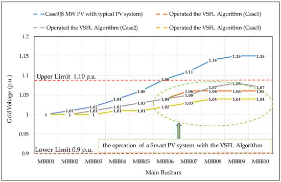
Figure 15.
Distribution voltage integrated a smart PV system with the VS-FL Algorithm. (Operate VS-VF Algorithm (case1) is a smart PV system operate as 0.2 MW electricity power charge to BSS when SOC is 0.9 and Grid Inverter operated at the PF 0.92 in case of PV power production equals 8 MW; Operate VS-FL Algorithm (case2) is a smart PV system operate as 0.8 MW electricity power charge to BSS when SOC is 0.5 and Grid Inverter operated at the PF 0.92 in case of PV power production equals 8 MW; Operate VS-FL Algorithm (case3) is a smart PV system operate as 1.8 MW electricity power charge to BSS when SOC is 0.3 and Grid Inverter operated at the PF 0.92 in case of PV power production equals 8 MW).
Figure 15 shows the simulation results by DIgsilant PowerFactory in the case of maximum power production from the PV system and low load consumption (Case 9). Case 9 was the worst case study in this research, over voltage due to high electricity power production from PV system which was injected into the distribution test system. According to the simulation, the distribution voltage at the MBB07 to MBB10 was over than over voltage limit of Thailand. For the case 9, if a distribution test system integrated with a smart PV system equipped with the VSFL Algorithm, it enabled to maintain the grid voltage into the target range (0.96 p.u.–1.06 p.u.) by two entities; The first entity was to manage the power production from PV system by charging electricity into the battery system, which was determined by the SOC value of the battery. After electricity was managed by the VSFL Algorithm to charge the battery system but the grid voltage at the PCC is not within the target range. A VSFL Algorithm will order the inverter to adjust the PF to maintain the grid voltage so call reactive power control. The scope of PF adjustment in this research was in rang of 0.90 lagging and 0.90 leading. From the result of simulation in case of over voltage, a smart PV system operated with the VSFL Algorithm enables to maintain the distribution voltage (MBB01 to MBB10) into the desired range.
Figure 16 shows the simulation results by DIgsilant PowerFactory in the case of no power production from the PV system with maximum load consumption (Case 1). Case 1 (load power consumption is maximum at 6 MW total capacity and no PV power production) was the worst case study for under voltage due to maximum electricity power consumption (6 MW) in the 22 kV distribution test system. Distribution voltage at the MBB06 to MBB10 was at very low voltage (0.91 p.u. of voltage at the MBB08 to MBB10). The grid voltage was out of the target range so a smart PV system equipped with the VSFL Algorithm operated to increase the grid voltage into the target range. To increase the distribution voltage into the target range, the VSFL Algorithm ordered a battery storage system to discharge electricity into the load within the distribution system. After operated the system resulted to distribution voltage form the MBB02 to MBB10 was increasing into the desired range. A smart PV system operated with the VSFL Algorithm can significantly enable to maintenance of the distribution voltage as presented in Figure 16.
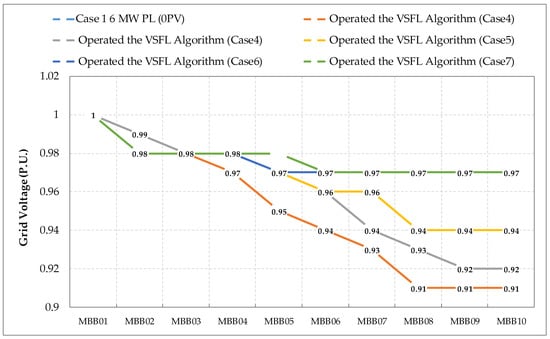
Figure 16.
Distribution voltage profile when operation a smart PV system with the VSFL Algorithm. Operated VSVF Algorithm (case4) is a smart PV system operation as 0 MW electricity power discharge from BSS when SOC is 0.3, no PV power production and 6 MW load power; Operated VSVF Algorithm (case5) is a smart PV system operate as 0.2 MW electricity power discharge from BSS when SOC is 0.4, no PV power production and 6 MW load power; Operated VSVF Algorithm (case6) is a smart PV system operate as 1.3 MW electricity power discharge from BSS when SOC is 0.5, no PV power production and 6 MW load power; Operated VSVF Algorithm (case7) is a smart PV system operation as 2.4 MW electricity power discharge from BSS when SOC is 0.5, no PV power production and 6 MW load power; Operated VSVF Algorithm (case8) is a smart PV system operation as 2.8 MW electricity power discharge from BSS when SOC is 0.5, no PV power production and 6 MW load power.
8. Conclusions
This paper discussed a concept of improving the typical PV system to a smart PV system for maintaining grid voltage stability. The concept of a smart PV system is that the battery storage system was assumed to integrate with a typical PV system and increase the grid inverter ability, increasing more capability for maintaining the distribution voltage into the target range (0.96 p.u. to 1.06 p.u. of voltage). This research started from test the grid inverter in an electrical laboratory on grid support functions, active and reactive power control depending on the grid voltage. The results of the test showed that the inverter management enabled to maintenance of the grid voltage stability. After analyzed the test results, the control algorithm was developed for a smart PV system by using the fuzzy logic method so called the VSFL Algorithm. To verify the operation of a smart PV system operated with the VSFL Algorithm so the existing 22 kV distribution system was connected with an 8 MW typical PV system in the northeast of Thailand, it was modified for voltage profile simulation by DIgsilent PowerFactory. Finally, the results of this research indicated that a smart PV system equipped with the VSFL Algorithm enabled to maintain of the distribution voltage into the target range by managing the battery storage system and grid inverter power management. Especially, in the case of over voltage due to a high amount of active power from the PV system fed to the grid, the VSFL Algorithm can significantly maintain the grid voltage into the target range. To improve the typical PV systems by adapting to a smart PV system is a solution to solve the problem of voltage fluctuation, which is effected by high penetration PV system.
Author Contributions
K.M. performed the simulation. K.M., S.S. and C.S. all participated in analysis of the results and writing of the paper.
Funding
This research received no external funding.
Acknowledgments
This research is a part of algorithm development for energy management in smart grid to mitigate the connection of high penetration PV system impact, which was supported by Naresuan University. Finally, the authors place there thankful for School of Renewable Energy Technology (SERT) staffs for supporting the technical data and their support during laboratory work.
Conflicts of Interest
The authors declare no conflict of interest.
References
- Scholar Report-Scott Macdonald. Solar Photovoltaic Energy in Thailand: An Assessment of Government Support Mechanisms; LSE Asia Research Centre (ARC): London, UK, 2012. [Google Scholar]
- Working Group of Ministry of Energy. Renewable Energy Outlook of Thailand; International Renewable Energy Agency (IRENA): Abu Dhabi, United Arab Emirates; Ministry of Energy Thailand: Bangkok, Thailand, 2017.
- Weck, S.; D’hulst, R.; Driesen, J. Locational pricing to mitigate voltage problems caused by high PV penetration. Energies 2015, 8, 4607–4628. [Google Scholar] [CrossRef]
- Yang, Y.; Zhang, W.; Jiang, J.; Huang, M.; Niu, L. Optimal scheduling of a battery energy storage system with electric vehicles’ auxiliary for a distribution network with renewable energy integration. Energies 2015, 8, 10718–10735. [Google Scholar] [CrossRef]
- Gunasekaran, M.; Mohamed Ismail, H.; Chokkalingam, B.; Mihet-Popa, L.; Padmanaban, S. Energy management strategy for rural communities’ DC Micro Grid power system structure with maximum penetration of renewable energy sources. Appl. Sci. 2018, 8, 585. [Google Scholar] [CrossRef]
- Mosadeghy, M.; Yan, R.; Saha, T.K. Impact of PV penetration level on the capacity value of South Australian wind farms. Renew. Energy 2016, 85, 1135–1142. [Google Scholar] [CrossRef]
- Haque, M.M.; Wolfs, P. A review of high PV penetration in LV distribution network: Present status impacts and mitigation measures. Renew. Sustain. Energy Rev. 2016, 62, 1195–1208. [Google Scholar] [CrossRef]
- Simoes, S.; Zeyringer, M.; Mayr, D.; Huld, T.; Nijs, W.; Schmidt, J. Impact of different levels of geographical disaggregation of wind and PV electricity generation in large energy system models: A case study for Austria. Renew. Energy 2017, 105, 183–198. [Google Scholar] [CrossRef]
- Xenias, D.; Axon, C.J.; Whitmarsh, L.; Connor, P.M.; Balta-Ozkan, N.; Spence, A. UK smart grid development: An expert assessment of the benefits, pitfalls and functions. Renew. Energy 2015, 81, 89–102. [Google Scholar] [CrossRef]
- Pukhrem, S.; Basu, M.; Conlon, M.F.; Sunderland, K. Enhanced network voltage management techniques under the proliferation of rooftop solar PV installation in Low-Voltage Distribution Network. IEEE J. Emerg. Sel. Top. Power Electron. 2017, 5, 681–694. [Google Scholar] [CrossRef]
- O’Connell, A.; Keane, A. Volt–var curves for photovoltaic inverters in distribution systems. IET Gener. Transm. Distrib. 2016, 11, 730–739. [Google Scholar] [CrossRef]
- Ghoddami, H.; Yazdani, A. A mitigation strategy for temporary over voltages caused by grid-connected photovoltaic systems. IEEE Trans. Energy Convers. 2015, 30, 413–420. [Google Scholar] [CrossRef]
- Ballanti, A.; Ochoa, L.F. On the integrated PV hosting capacity of MV and LV distribution networks. In Proceedings of the IEEE PES Innovative Smart Grid Technologies Latin America (ISGT LATAM), Montevideo, Uruguay, 5–7 October 2015; pp. 366–370. [Google Scholar] [CrossRef]
- Armendariz, M.; Brodén, D.; Honeth, N.; Nordström, L. A method to identify exposed nodes in low voltage distribution grids with High PV penetration. In Proceedings of the IEEE Power & Energy Society General Meeting, Denver, CO, USA, 26–30 July 2015; pp. 1–5. [Google Scholar] [CrossRef]
- Patsalides, M.; Efthymiou, V.; Stavrou, A.; Georghiou, G.E. A generic transient PV system model for power quality studies. Renew. Energy 2016, 89, 526–542. [Google Scholar] [CrossRef]
- Working group of PEA. Provincial Electricity Authority’s Regulation on the Power Network System Interconnection Code B.E. 2559; Provincial Electricity Authority of Thailand: Ladyao, Jatujak Bangkok, 2016. [Google Scholar]
- Hossain, M.S.; Madlool, N.A.; Rahim, N.A.; Selvaraj, J.; Pandey, A.K.; Khan, A.F. Role of smart grid in renewable energy: An overview. Renew. Sustain. Energy Rev. 2016, 60, 1168–1184. [Google Scholar] [CrossRef]
- Zafar, R.; Mahmood, A.; Razzaq, S.; Ali, W.; Naeem, U.; Shehzad, K. Prosumer based energy management and sharing in smart grid. Renew. Sustain. Energy Rev. 2017, 82, 1675–1684. [Google Scholar] [CrossRef]
- Williams, T.; Wang, D.; Crawford, C.; Djilali, N. Integrating renewable energy using a smart distribution system: Potential of self-regulating demand response. Renew. Energy 2013, 52, 46–56. [Google Scholar] [CrossRef]
- Jha, S.K.; Bilalovic, J.; Jha, A.; Patel, N.; Zhang, H. Renewable energy: Present research and future scope of artificial intelligence. Renew. Sustain. Energy Rev. 2017, 77, 297–317. [Google Scholar] [CrossRef]
- Hua, Y.; Oliphant, M.; Hu, E.J. Development of renewable energy in Australia and China: A comparison of policies and status. Renew. Energy 2014, 85, 1044–1051. [Google Scholar] [CrossRef]
- Brundliger, L. High Penetration of PV in Local Distribution Grid: Case-Study Collection; Report IEA PVPS: Ursen, Switzerland, 2014; ISBN 978-3-906042-23-7. [Google Scholar]
- Karimi, M.; Mokhlis, H.; Naidu, K.; Uddin, S.; Bakar, A.H.A. Photovoltaic penetration issues and impacts in distribution network-A review. Renew. Sustain. Energy Rev. 2016, 53, 594–605. [Google Scholar] [CrossRef]
- Zhou, N.; Liu, N.; Zhang, J.; Lei, J. Multi-objective optimal sizing for battery storage of PV-based microgrid with demand response. Enegies 2016, 9, 591. [Google Scholar] [CrossRef]
- Hussain, A.; Bui, V.H.; Kim, H.M. Fuzzy logic-based operation of battery energy storage systems (BESSs) for enhancing the resiliency of hybrid microgrids. Enegies 2016, 10, 271. [Google Scholar] [CrossRef]
- Watson, J.D.; Watson, N.R.; Santos-Martin, D.; Wood, A.R.; Lemon, S.; Miller, A.J. Impact of solar photovoltaics on the low-voltage distribution network in New Zealand. IET Gener. Transm. Distrib. 2016, 10, 1–9. [Google Scholar] [CrossRef]
- Hashemi1, S.; Stergaard, J. Methods and strategies for overvoltage prevention in low voltage distribution systems with PV. IET Renew. Power Gener. 2016, 11, 205–214. [Google Scholar] [CrossRef]
- Li, Y.; Ishikawa, M. An efficient reactive power control method for power network systems with solar photovoltaic generators using sparse optimization. Energies 2017, 10, 696. [Google Scholar] [CrossRef]
- Moger, T.; Dhadbanjan, T. Fuzzy logic approach for reactive power coordination in grid connected wind farms to improve steady state voltage stability. IET Renew. Power Gener. 2017, 11, 351–361. [Google Scholar] [CrossRef]
- Suganthi, L.; Iniyan, S.; Samuel, A.A. Applications of fuzzy logic in renewable energy systems—A review. Renew. Sustain. Energy Rev. 2015, 48, 585–607. [Google Scholar] [CrossRef]
- Sukumar, S.; Marsadek, M.; Ramasamy, A.; Mokhlis, H.; Mekhilef, S. A fuzzy-based PI controller for power management of a grid-connected PV-SOFC hybrid system. Energies 2017, 10, 1720. [Google Scholar] [CrossRef]
- Ciabattoni, L.; Ferracuti, F.; Grisostomi, M.; Ippoliti, G.; Longhi, S. Fuzzy logic based economic analysis of photovoltaic energy management. Neurocomputing 2015, 170, 296–305. [Google Scholar] [CrossRef]
- Arcos-Aviles, D.; Pascual, J.; Marroyo, L.; Sanchis, P.; Guinjoan, F. Fuzzy logic-based energy management system design for residential grid-connected microgrids. IEEE Trans. Smart Grid 2018, 9, 530–540. [Google Scholar] [CrossRef]
© 2018 by the authors. Licensee MDPI, Basel, Switzerland. This article is an open access article distributed under the terms and conditions of the Creative Commons Attribution (CC BY) license (http://creativecommons.org/licenses/by/4.0/).