Abstract
The performance of multiphase pumps has a remarkable influence on the related industrial application. In order to understand the flow field and gas-liquid phase interaction characteristics of a multiphase rotodynamic pump, detailed numerical analysis of the pump with a medium of air-water combination was carried out for the whole flow passage by means of a structured mesh using ICEM_CFD and TurboGrid. The results for 21% inlet gas void fraction (IGVF = 21%) condition showed that the magnitude ratio of non-drag forces to drag in impeller and guide vane passages was generally less than 1, whereas it was always less than 0.2 for the magnitude ratio of turbulent dispersion force to drag. When the IGVF was increased, the variation range of interphase forces in the impeller was greater than that in the guide vane. In addition, the gas in the impeller mainly accumulated near the suction surface in the outlet region. Further, with increased IGVF, the degree of aggregation increased as well as the gas inhomogeneity, and consequently the interphase forces in the impeller increased. Due to the divergent structure of the guide vane, obvious vortexes emerged at the hub and gradually moved toward the blade pressure surface along the streamwise direction.
1. Introduction
The extensive use of multiphase pumps for handling gas-liquid two-phase flow is not restricted to petroleum, but also occurs in other industrial applications including chemical engineering, food, urban water supply, and nuclear industries [1,2,3]. Multiphase pumps are generally grouped into positive displacement and rotodynamic pumps. Compared to the positive displacement pump, the rotodynamic pump has many advantages, such as smaller volume, larger discharge, lower requirement for manufacture precision, lower sensitivity to solid particles in the flow field, easier use and repair, and so on [4,5]. In addition, compared to the single-phase pump, the rotodynamic pump is often accompanied by many complex phenomena because of the rotation of the impeller and the rotor-stator interaction, such as the coalescence and breakup of bubbles, and the separation and intermixing between two phases [6].
In recent years, many studies have been performed through experiment and simulation on the gas-liquid multiphase pumps. Murakami and Minemura [7,8] observed the flow regime in a centrifugal pump and grouped the flow patterns into isolated bubbles flow, bubbly flow, gas pocket flow, and segregated gas flow. Verde et al. [9] classified the flow pattern in a centrifugal pump into bubble flow, agglomerated bubble flow, gas pocket flow, and segregated flow, and observed that the gas pocket flow was related to the intensification of performance degradation. Meanwhile, Zhang et al. [10,11] found that the relationship between bubble number and bubble size obeyed a normal distribution in the inlet region of a rotodynamic multiphase pump, and the bubble size increased with increased IGVF while it decreased with increased rotational speed. Overall, the experimental studies for gas-liquid multiphase pumps were focused on the external characteristics (efficiency, head, etc.) and flow regime characteristics [12,13,14]. However, because the multiphase rotodynamic pump is a high-speed rotating machine, it is difficult to get more comprehensive flow regime transition information using the experimental method. Furthermore, some field parameters are also impossible to obtain experimentally based on the current monitoring techniques (e.g., the interphase behavior information).
Computational fluid dynamics (CFD) technology has become an important method to study the performance and internal flow characteristics in multiphase pumps [15]. For example, Zhu et al. [16] developed a mechanistic model for predicting the in-situ GVF inside an electrical submersible pump, and verified its reliability using three-dimensional (3D) CFD simulations. Tremante et al. [17] conducted simulations on a NACA65 axial flow pump with a medium of air-water combination. They observed the extension of gas pocket from the impeller inlet to the pressure surface, along with the formation of a stratified flow structure at large angles of attack. The particular two-phase flow model used is a key factor determining the accuracy of the CFD simulation of a multiphase pump. According to the literature on gas-liquid two-phase models, the two-fluid model was most widely adopted because of its high calculation accuracy compared to other models such as mixture model and drift flow model, etc. [18,19]. However, the selection and computational analysis of interphase forces are also crucial to the two-fluid model. Although the magnitude of interphase forces in a rotodynamic pump impeller was analyzed by Yu et al. [20,21], the rotor-stator interaction was ignored because the guide vane was not included in the computational model.
Overall, exploration of the internal flow characteristics in multiphase rotodynamic pumps handling gas-liquid two-phase flow is still insufficient, especially for gas-liquid interphase behavior. The objective of the present study was to develop an in-depth understanding of the gas-liquid phase interaction characteristics and analyze the cause of gas-liquid flow separation in multiphase rotodynamic pumps, which will help in the design optimization for such pumps. In this study, detailed 3D simulations were carried out for the whole flow passage of a multiphase rotodynamic pump based on interphase force analysis. The combination of air and water was used as the medium to investigate the gas void fraction and the gas-liquid interphase behavior in impeller and guide vane passages at different inlet gas void fractions (IGVFs).
2. Test System
A schematic diagram of the test system of the multiphase pump is presented in Figure 1. In order to ensure the safety of experiment and the reusability of equipment, air-water was used as the working medium. In the experiment, water that flowed out from the water tank was mixed evenly with the air provided by a compressor in a swirling mixer [11], then they entered the pump. The gas and water flowed back to the water tank after experiencing the work behavior of the multiphase pump, and then the gas spilled out from the water tank. Additionally, the water and gas discharges were measured by the turbine and float flowmeters, respectively, with an accuracy grade of ±1.5%. The accuracy grade of the pressure gauges located at the water and gas pipelines and the inlet and outlet of the pump was ±0.25%, while the rotational speed, power, and torque of this pump were measured by a CYT-302 series torque meter, with an accuracy of ±0.2%.

Figure 1.
Schematic diagram of the test system of the multiphase pump.
Figure 2 shows the test helico-axial pump model with its impeller and guide vane, inlet and outlet pipes. In order to observe the internal flow in this pump with a high-speed camera, the shell of the impeller and guide vane were made of organic glass, as displayed in Figure 2. Table 1 shows the dimension and design details of the multiphase pump. Here, according to the following Equations (1)–(3), the design specific speed, design discharge, and head coefficients were determined as 166, 0.168, and 0.274, respectively:
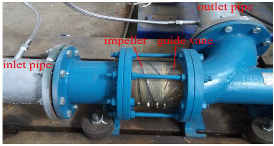
Figure 2.
Test pump model.

Table 1.
The dimension and design details of the multiphase pump.
3. Numerical Methodology
3.1. Governing Equations
The steady Reynolds-averaged Navier–Stokes (RANS) equations were solved using ANSYS_CFX 16.0 (SAS IP, Inc., Pittsburgh, PA, USA). The continuity and momentum equations for incompressible flow were written in the Cartesian coordinate system as follows [21,22,23]:
where αk and Uk denote respectively the void fraction and velocity of phase k, Mk is the interphase force, fk stands for the mass force, and τ denotes the viscous stress related to the molecular viscosity and turbulent viscosity. The components of the viscous stress tensor can be expressed as follows:
where I is the unit tensor. stands for the effective viscosity as follows [18]:
where and represent the dynamic viscosity and the turbulent viscosity, respectively.
The turbulent viscosity is solved using the shear stress transport (SST) k-ω model which combines the advantages of k-ε and k-ω turbulence models. That is, the k-ε and k-ω models are employed for the near-wall and mainstream regions, respectively. Therefore, this model has high accuracy in predicting flow separation under adverse pressure gradient. Here, the turbulent viscosity can be expressed as follows [24,25,26]:
also,
where and β′ are the model constants ( = 5/9, β′ = 0.09), k and ω stand for turbulence kinetic energy, and turbulence frequency, respectively.
3.2. Interphase Forces
The gas-liquid interphase forces usually include drag, added mass, lift, turbulent dispersion, as well as Basset effect and Magnus effect [27], where the Basset effect and Magnus effect consider the historical acceleration effect and the rotation effect of the bubbles, respectively. However, according to the related studies, the Basset effect and Magnus effect can be ignored in multiphase pumps [20,28]. Therefore, the total interphase force can be expressed as follows:
Here, Dk, Ak, Lk, and Tk represent the interphase forces of drag, added mass, lift, and turbulent dispersion, respectively. These four interphase forces expressions are listed in Table 2, where Ug and Ul stand for the velocity of gas and liquid, respectively, and Db denotes the diameter of gas bubbles.
Table 2.
Information on expressions of the gas-liquid interphase forces.
3.3. Structured Mesh Information
The numerical model in this study includes four parts: inlet and outlet pipes, impeller, and guide vane. The mesh of the first two parts was generated using ICEM_CFD 16.0 (SAS IP, Inc., Pittsburgh, PA, USA), while in order to improve the mesh quality, the latter two parts adopted H/J/C/O topology structures using TurboGrid 16.0 (SAS IP, Inc., Pittsburgh, PA, USA). The domain mesh for the pump model is displayed in Figure 3a, and the meshes for impeller and guide vane are shown in Figure 3b,c, respectively.
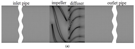
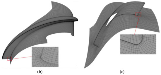
Figure 3.
Structured mesh for analysis. (a) Computational domain; (b) Impeller; (c) Guide vane.
In order to make good use of the computational resources and reduce the size of memory and computational time, mesh independence analysis was conducted at pure water designed discharge conditions, as listed in Table 3. The analysis showed that the mesh densities of Mesh III and Mesh IV produced only a small difference in the head and efficiency of the pump. Therefore, Mesh III was ultimately chosen in this study. Meanwhile, the detailed mesh information for each part of Mesh III was counted to ensure that the mesh quality could meet the computational demand, as shown in Table 4. This information shows that all the indicators of orthogonality angle, mesh expansion factor, aspect ratio, and y+ value of impeller and guide vane could meet the requirements of the turbulence model adopted in this study.
Table 3.
Mesh independence analysis.
Table 4.
Detailed mesh information for each part of Mesh III.
3.4. Boundary Conditions and Numerical Solution Settings
The bulk mass discharge and the corresponding gas void fraction of each medium were specified at the inlet of the computational domain. At the outlet, the average static pressure was applied, and the no-slip condition was adopted at all wall boundaries. Meanwhile, the frozen-stator method was imposed for the rotor-stator interaction region (inlet pipe-impeller, impeller-guide vane), which can produce a steady solution to the multiple frame of reference problem. The details of solution strategy are presented in Table 5.
Table 5.
Numerical solution strategy. RMS: root mean square.
4. Results and Discussions
4.1. Model Validation
The simulation and experimental results at IGVF = 0% (pure water) are shown in Figure 4. The efficiency and head curves from the calculation show close agreement with the experiment. The errors of efficiency and head at pure water design condition were 0.94% and 2.97%, respectively. Table 6 lists the values of head with different IGVFs at conditions of n = 2950 rpm and φ = 0.274. The errors of head between simulation and experiment were relatively small at IGVFs of 9%, 15%, and 21%, and the maximum relative error was only 3.30% at IGVF = 15%. According to the above analysis, the conclusion can be drawn that the numerical strategy adopted in this study was reliable.
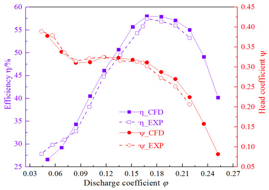
Figure 4.
Comparison of performance results between simulation and experiment (IGVF = 0%). CFD: computational fluid dynamics; EXP: experiment.
Table 6.
Values of head with different IGVFs for simulation and experiment (Q = 50 m3/h).
4.2. Phase Interaction Characteristics in Impeller and Guide Vane
To analyze phase interaction characteristics of the gas-liquid flow in the multiphase rotodynamic pump, the area average of interphase forces were extracted along the streamwise direction. Taking the IGVF = 21% condition as an example, the magnitude ratio of non-drag forces—including added mass, lift, and turbulent dispersion—to drag along the streamwise direction is shown in Figure 5. Overall, for the interphase forces in impeller and guide vane passages, the magnitude ratio of non-drag forces to drag was generally less than 1, while it was always less than 0.2 for the magnitude ratio of turbulent dispersion force to drag, which indicates that the drag was dominant and the turbulent dispersion force was very small relative to the drag for the interphase forces in the multiphase rotodynamic pump. It can be also seen from Figure 5 that the drag force was the largest overall in the impeller and guide vane, followed by the lift and added mass forces, then the turbulent dispersion force.
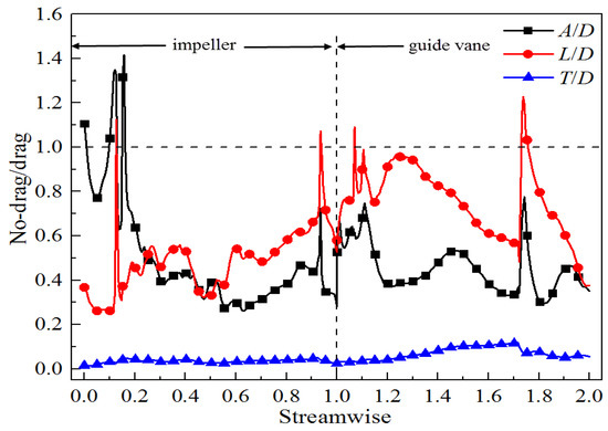
Figure 5.
Magnitude ratio of non-drag forces to drag along the streamwise direction at IGVF = 21%.
According to the above analysis, the turbulent dispersion force was much smaller relative to the other three interphase forces. Therefore, Figure 6 only shows the interphase forces of drag, lift, and added mass along the streamwise direction from impeller inlet to guide vane outlet at different IGVFs. These three interphase forces increased significantly near the inlet and outlet of the impeller. Still taking the IGVF = 21% condition as an example, it should be attributed to the rotating effect of the impeller. The flow near the impeller inlet changes from non-swirling to swirling, resulting in enlarged liquid superficial velocity (Figure 7a). On the other hand, due to the rotor-stator interaction, the flow of the two phases near the impeller outlet is more disordered, resulting in the emergence of obvious vortexes (Figure 7). Therefore, the enlarged superficial velocity difference between gas and liquid phases occurs in the inlet and outlet of the impeller (Figure 8). Then, combined with the calculation expressions, it can be concluded that the interphase forces of drag, added mass, and lift near the inlet and outlet of the impeller would increase significantly.
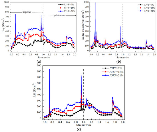
Figure 6.
Distribution of interphase forces along the streamwise direction at different IGVFs. (a) Drag force; (b) Added mass force; (c) Lift force.
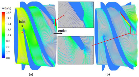
Figure 7.
Distribution of superficial velocity in the impeller at IGVF = 21%. (a) Liquid superficial velocity; (b) Gas superficial velocity.
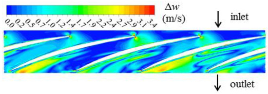
Figure 8.
Distribution of velocity difference between the two phases in the impeller at IGVF = 21% (span = 0.5).
Overall, the interphase forces in impeller and guide vane passages became large if the IGVF increased. With increased IGVF, the variation range of interphase forces in the impeller was greater than that in the guide vane, which is closely related to the more complicated gas-liquid flow and the larger interphase forces in the impeller that are both aroused by the rotating effect.
4.3. Gas Distribution in the Impeller Passage
The area average of gas distribution along the streamwise direction in the impeller at different IGVFs (9%, 15%, and 21%) are shown in Figure 9. At these three IGVF conditions, the gas in the impeller mainly accumulated near the hub. This is aroused by the rotating effect of the impeller. As the density of water is higher, it will experience larger centrifugal force, and as a result, moves toward the impeller shroud, whereas the gas moves to and gathers at the impeller hub. With the increased IGVF, the degree of aggregation of the gas in the impeller hub increased as well as the gas inhomogeneity, which is also why the interphase forces in the impeller increased with the increased IGVF. According to the calculation expressions, this is because the gas void fraction is one of the factors that affect the interphase forces of drag, added mass and lift, and has a positive correlation with these three interphase forces.
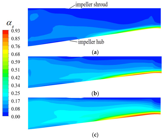
Figure 9.
Distribution of gas void fraction along the streamwise direction at different IGVFs. (a) IGVF = 9%; (b) IGVF = 15%; (c) IGVF = 21%.
It can also be seen from Figure 9 that the gas mainly accumulated near the hub of the impeller outlet. This is partly due to the action of the impeller. The gas moves toward the impeller outlet and also suffers from an adverse pressure gradient, thus resulting in a reverse flow of gas near the hub of impeller outlet, as presented in Figure 10a,b respectively. On the other hand, because the pressure near the impeller shroud is greater than that in the impeller hub, the gas in impeller suffers from a pressure difference from shroud to hub. The above reasons result in the gas mainly accumulating near the hub of impeller outlet. Then, combined with the calculation expressions, the gas accumulation near the hub of impeller outlet will enlarge the interphase forces therein, which is in accordance with the analysis of Figure 6.
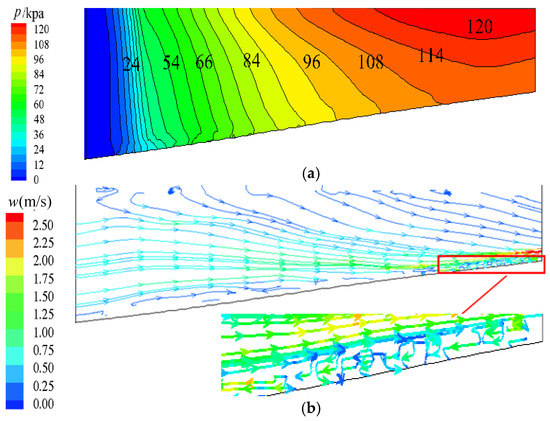
Figure 10.
Pressure and streamlines distribution of S2 stream surface in middle of the impeller (IGVF = 15%). (a) Pressure distribution of S2 stream surface in the middle of the impeller; (b) Streamlines distribution of S2 stream surface in the middle of the impeller.
Figure 11 shows the gas distribution of the impeller hub at IGVFs of 9%, 15%, and 21% (span = 0.1). At different IGVFs, the gas near the hub of the impeller outlet mainly accumulated near the blade suction surface, and the higher the IGVF, the higher the aggregation degree therein. It can also be seen that the gas distribution in these four passages was asymmetric, which illustrates that the flow in the multiphase rotodynamic pump was more disordered, and a gas block phenomenon may occur first in an individual impeller passage with the increased IGVF.
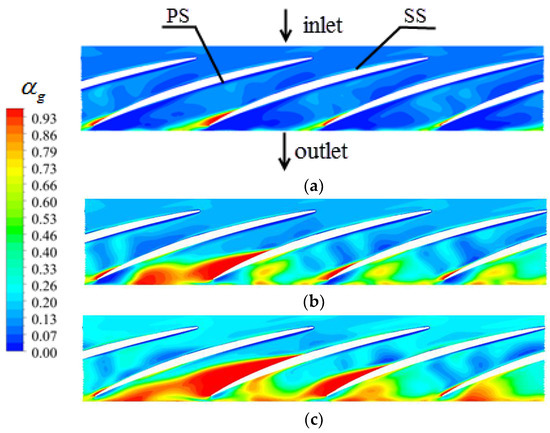
Figure 11.
Gas distribution near the impeller hub at different IGVFs (span=0.1). (a) IGVF = 9%; (b) IGVF = 15%; (c) IGVF = 21%. PS: pressure surface; SS: suction surface.
According to the above analysis, due to the rotation effect of the impeller and the adverse pressure gradient in the flow passages, the gas in the impeller mainly accumulated near the hub of the impeller outlet. The higher the IGVF, the higher the aggregation degree and gas inhomogeneity therein, thus resulting in increased interphase forces in the impeller passage.
4.4. Gas Distribution in the Guide Vane Passage
The gas void fractions and 3D streamline distributions of the S2 stream surface in the middle of the guide vane at different IGVFs are shown in Figure 12. The regularities of gas distribution in the guide vane are similar at different IGVFs, mainly accumulating near the guide vane hub, and gradually spreading to the mainstream region along the streamwise direction in the guide vane. This can be ascribed to the accumulated gas near the hub of the impeller outlet moving toward the guide vane because of inertia. On the other hand, the effect of centrifugal force in the guide vane will disappear, resulting in the gas in the guide vane moving along the streamwise direction and also spreading to the mainstream region.
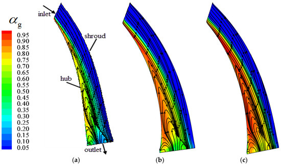
Figure 12.
Gas void fraction and 3D streamline distributions of S2 stream surface in the middle of the guide vane at different IGVFs. (a) IGVF = 9%; (b) IGVF = 15%; (c) IGVF = 21%.
It can be seen from the streamline distribution of gas that obvious gas vortexes emerged at the hub of the guide vane, and their ranges increased gradually from the inlet to the outlet of the guide vane. This is due to the divergent structure of the guide vane. The gas velocity decreased gradually along the streamwise direction, and the gas also experienced an adverse pressure gradient, which together resulted in flow separation near the guide vane hub. Meanwhile, with increased IGVF, the degree of aggregation of gas and the range of gas vortexes—both located near the guide vane hub—became larger.
In the present study, the Q-criterion was used to further explore the vortexes structure in the guide vane. Figure 13 shows the structure of gas vortexes in the guide vane at different IGVFs, and the magnitude of the iso-surface Q was calculated by the following expressions [31,32]:
where S and Ω are the symmetric and antisymmetric parts of the velocity gradient tensor, respectively. That is, S and Ω stand for the deformation and the rotation of the local position in the flow field, respectively. Therefore, the rotation is dominant if the magnitude of Q is positive.
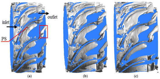
Figure 13.
Structure of gas vortexes in the guide vane at different IGVFs (Q = 2 × 10⁵). (a) IGVF = 9%; (b) IGVF = 15%; (c) IGVF = 21%.
It can be seen from Figure 13 that obvious gas vortexes occurred at the guide vane inlet at different IGVFs when Q = 2 × 10⁵. This was due to the strong gas-liquid phase interaction and more disordered flow which were both aroused by the rotor-stator interaction. Along the streamwise direction in the guide vane, the gas vortexes gradually moved toward the blade pressure surface and also spread from hub to mainstream region, which is in accordance with the analysis of Figure 12. In addition, trumpet-shaped gas vortexes formed near the trailing edge of the guide vane blades, which may be closely related with the jet wake structure of the guide vane. Then, combined with the analysis of Figure 6, it can be concluded that the sudden increased interphase forces of drag, added mass, and lift are closely related to the complex turbulent structure near the trailing edge of guide vane blades.
5. Conclusions
The objective of the present study was to develop an in-depth understanding of the gas-liquid phase interaction characteristics and analyze the cause of gas-liquid flow separation in multiphase rotodynamic pumps. Through the numerical calculation, the distribution of gas void fraction as well as the gas-liquid interphase behavior in the pump were explored at different IGVFs. The conclusions can be drawn as follows:
- (1)
- For the interphase forces in impeller and guide vane passages at IGVF = 21%, the magnitude ratio of non-drag forces to drag was generally less than 1, while the magnitude ratio of turbulent dispersion force to drag was always less than 0.2, which indicates that the drag was dominant and the turbulent dispersion force was very small relative to the drag in the multiphase rotodynamic pump.
- (2)
- Due to the rotation of the impeller and the rotor-stator interaction, the interphase forces of drag, added mass, and lift near the inlet and outlet of the impeller increased significantly. Meanwhile, with the increased IGVF, the variation range of interphase forces in the impeller was greater than that in the guide vane.
- (3)
- Due to the rotation effect of the impeller and the adverse pressure gradient in the flow passages, the gas in the impeller mainly accumulated near the hub of the impeller outlet. The higher the IGVF, the higher the aggregation degree and gas inhomogeneity therein, thus resulting in the increased interphase forces in the impeller passage.
- (4)
- The regularities of gas distribution in the guide vane were similar at different IGVFs, mainly accumulating near the guide vane hub, and gradually spreading to the mainstream region along the streamwise direction. Additionally, due to the divergent structure of the guide vane, obvious vortexes emerged at the hub. With increased IGVF, the degree of aggregation of gas and the range of gas vortexes—which are both located near the guide vane hub—became larger.
Author Contributions
Zhiyi Yu designed the experiments; Wenwu Zhang and Yongjiang Li carried out the experiments; Wenwu Zhang and Zhiyi Yu wrote the paper; Muhammad Noaman Zahid improved the language.
Acknowledgments
This study was supported by the National Natural Science Foundation of China (51579006), and Basic Research Foundation of Beijing Institute of Technology (20150342012).
Conflicts of Interest
The authors declare no conflict of interest.
Nomenclature
| Ak | Additional mass force of phase k, N/m3 |
| Model constant, dimensionless | |
| CA | Coefficient of additional mass force, dimensionless |
| CD | Drag coefficient, dimensionless |
| CL | Lift coefficient, dimensionless |
| cm2 | Meridional velocity at impeller outlet, m/s |
| CT | Coefficient of turbulent dispersion force, dimensionless |
| Db | Bubble diameter, mm |
| Dh1 | Hub diameter of impeller inlet, mm |
| Dh2 | Hub diameter of impeller outlet, mm |
| Dh3 | Hub diameter of guide vane inlet, mm |
| Dh4 | Hub diameter of guide vane outlet, mm |
| Dk | Drag force of phase k, N/m3 |
| Ds1 | Impeller shroud diameter, mm |
| Ds2 | Guide vane shroud diameter, mm |
| F2 | Blending function in SST-k-ω model |
| f | Mass force relevant to the rotation of the impeller, m/s2 |
| H | Pump head, m |
| Hd | Pump design head, m |
| Hl | Impeller axial length, mm |
| H2 | Guide vane axial length, mm |
| IGVF | Inlet gas void fraction, dimensionless |
| k | Turbulent kinetic energy, m2/s2 |
| Lk | Lift force of phase k, N/m3 |
| Mk | Total interphase force per unit volume, N/m3 |
| n | Rotational speed, r/min |
| ns | Specific speed, m3/4·s−3/2 |
| p | Static pressure, kPa |
| Q | Q-criterion |
| qv | Discharge, m3/s |
| Re | Reynolds number, dimensionless |
| SkΦ | Source item |
| S | Invariant measure of the strain rate |
| Tk | Turbulent dispersion force of phase k, N/m3 |
| Ug | Gas velocity, m/s |
| Ul | Liquid velocity, m/s |
| u2 | Velocity of the impeller outlet, m/s |
| w | Relative velocity, m/s |
| Z1 | Impeller blade numbers, mm |
| Z2 | Guide vane blade numbers, mm |
| Greek symbols | |
| αk | Volume fraction of phase, % |
| β′ | Model constant, dimensionless |
| ΓkΦ | Diffusion coefficient, dimensionless |
| σ | Surface tension coefficient, N/m |
| μk,t | Turbulent viscosity, Pa·s |
| μ | Molecular viscosity, Pa·s |
| μkeff | Effective viscosity, Pa·s |
| Density of phase k, kg/m3 | |
| Mixture density of phases, kg/m3 | |
| Φk | Universal variable |
| φ | Discharge coefficient, dimensionless |
| ψ | Head coefficient, dimensionless |
| ω | Rotational frequency of the impeller, 1/s |
| Subscripts | |
| k | Phase |
| g | Gas phase |
| l | Liquid phase |
References
- Omrani, A.E.; Franchek, M.A.; Ebrahimi, B.; Mutlu, M.; Grigoriadis, K. Low-dimensional modeling of a pumping unit to cope with multiphase. J. Dyn. Syst. Meas. Control 2017, 139, 041010. [Google Scholar] [CrossRef]
- Pirouzpanah, S.; Gudigopuram, S.R.; Morrison, G.L. Two-phase flow characterization in a split vane impeller Electrical Submersible Pump. J. Pet. Sci. Eng. 2016, 148, 82–93. [Google Scholar] [CrossRef]
- Suh, J.W.; Kim, J.W.; Choi, Y.S.; Kim, J.H.; Joo, W.G.; Lee, K.Y. Multi-objective optimization of the hydrodynamic performance of the second stage of a multi-phase pump. Energies 2017, 10, 1334. [Google Scholar] [CrossRef]
- Sun, J.W.; Kim, J.H.; Choi, Y.S.; Joo, W.G.; Lee, K.Y. A study on numerical optimization and performance verification of multi-phase pump for offshore plant. Proc. Inst. Mech. Eng. Part A J. Power 2017, 231, 095765091770226. [Google Scholar]
- Cao, S.L.; Peng, G.Y.; Yu, Z.Y. Hydrodynamic design of rotodynamic pump impeller for multiphase pumping by combined approach of inverse design and CFD analysis. J. Fluids Eng. 2005, 127, 330. [Google Scholar] [CrossRef]
- Zhang, W.W.; Yu, Z.Y.; Zhu, B.S. Numerical study of pressure fluctuation in a gas- liquid two-phase mixed-flow pump. Energies 2017, 10, 634. [Google Scholar] [CrossRef]
- Minemura, K.; Murakami, M. A theoretical study on air bubble motion in a centrifugal pump impeller. J. Fluids Eng. 1980, 102, 446–453. [Google Scholar] [CrossRef]
- Minemura, K.; Murakami, M. Three-dimensional calculation of air-water twophase flow in centrifugal pump impeller based on a bubbly flow model. J. Fluid. Eng. Trans. ASME 1993, 115, 766–771. [Google Scholar] [CrossRef]
- Verde, W.M.; Biazussi, J.L.; Sassim, N.A.; Bannwart, A.C. Experimental study of gas-liquid two-phase flow patterns within centrifugal pumps impellers. Exp. Therm. Fluid Sci. 2017, 85, 37–51. [Google Scholar] [CrossRef]
- Zhang, J.Y.; Cai, S.J.; Li, Y.J.; Zhu, H.W.; Zhang, Y.X. Visualization study of gas-liquid two-phase flow patterns inside a three-stage rotodynamic multiphase pump. Exp. Therm. Fluid. Sci. 2016, 70, 125–138. [Google Scholar] [CrossRef]
- Zhang, J.Y.; Cai, S.J.; Zhu, H.W.; Zhang, Y.X. Experimental investigation of the flow at the entrance of a rotodynamic multiphase pump by visualization. J. Pet. Sci. Eng. 2015, 126, 254–261. [Google Scholar] [CrossRef]
- Sato, S.; Furukawa, A.; Takamatsu, Y.; Sato, S.; Furukawa, A.; Takamatsu, Y. Air-water two-phase flow performance of centrifugal pump impellers with various blade angles. Bull. JSME 2008, 39, 223–229. [Google Scholar] [CrossRef]
- Poullikkas, A. Effects of two-phase liquid-gas flow on the performance of nuclear reactor cooling pumps. Prog. Nucl. Energy 2003, 42, 3–10. [Google Scholar] [CrossRef]
- Schäfer, T.; Bieberle, A.; Neumann, M.; Hampel, U. Application of gamma-ray computed tomography for the analysis of gas holdup distributions in centrifugal pumps. Flow Meas. Instrum. 2015, 46, 262–267. [Google Scholar] [CrossRef]
- Yan, D.; Kovacevic, A.; Tang, Q.; Rane, S.; Zhang, W.H. Numerical modelling of twin-screw pumps based on computational fluid dynamics. Proc. Inst. Mech. Eng. Part C 2016, 231, 4617–4634. [Google Scholar] [CrossRef]
- Zhu, J.J.; Zhang, H.Q. Mechanistic modeling and numerical simulation of in-situ gas void fraction inside ESP impeller. J. Nat. Gas Sci. Eng. 2016, 36, 144–154. [Google Scholar] [CrossRef]
- Tremante, A.; Moreno, N.; Rey, R. Numerical turbulent simulation of the two–phase flow (1iquid/gas) through a cascade of an axial pump. ASME J. Fluids Eng. 2002, 124, 371–376. [Google Scholar] [CrossRef]
- Benhmidene, A.; Chaouachi, B.; Bourouis, M.; Gansi, S. Numerical prediction of flow patterns in bubble pumps. J. Fluid Eng. 2011, 133, 031302. [Google Scholar] [CrossRef]
- Situ, R.; Hibiki, T.; Brown, R.J. Flow regime transition criteria for two-phase flow at reduced gravity conditions. Int. J. Multiph. Flow 2011, 37, 1165–1177. [Google Scholar] [CrossRef]
- Yu, Z.Y.; Zhu, B.S.; Cao, S.L.; Liu, Y. Effect of virtual mass force on the mixed transport process in a multiphase rotodynamic pump. Adv. Mech. Eng. 2015, 6. [Google Scholar] [CrossRef]
- Yu, Z.Y.; Zhu, B.S.; Cao, S.L. Interphase force analysis for air-water bubbly flow in a multiphase rotodynamic pump. Eng. Comput. 2015, 32, 2166–2180. [Google Scholar] [CrossRef]
- Tabib, M.V.; Schwarz, P. Quantifying sub-grid scale (SGS) turbulent dispersion force and its effect using one-equation SGS large eddy simulation (LES) model in a gas-liquid and a liquid-liquid system. Chem. Eng. Sci. 2011, 66, 3071–3086. [Google Scholar] [CrossRef]
- Lane, G.L.; Schwarz, M.P.; Evans, G.M. Numerical modelling of gas-liquid flow in stirred tanks. Chem. Eng. Sci. 2005, 60, 2203–2214. [Google Scholar] [CrossRef]
- Tan, L.; Zhu, B.S.; Wang, Y.C.; Cao, S.L.; Gui, S.B. Numerical study on characteristics of unsteady flow in a centrifugal pump volute at partial load condition. Eng. Comput. 2015, 32, 1549–1566. [Google Scholar] [CrossRef]
- Zhang, W.W.; Yu, Z.Y.; Zhu, B.S. Influence of tip clearance on pressure fluctuation in low specific speed mixed-flow pump passage. Energies 2017, 10, 148. [Google Scholar] [CrossRef]
- Hao, Y.; Tan, L.; Liu, Y.b.; Xu, Y.; Zhang, J.S.; Zhu, B.S. Energy performance and radial force of a mixed-flow pump with symmetrical and unsymmetrical tip clearances. Energies 2017, 10, 57. [Google Scholar] [CrossRef]
- Liu, D.Y. Fluid Dynamics of Two-Phase Systems; Higher Education Press: Beijing, China, 1993; pp. 26–31. [Google Scholar]
- Johnson, R.W. The Handbook of Fluid Dynamics; CRC Press: Boca Raton, FL, USA, 1998; pp. 21–22. [Google Scholar]
- Pourtousi, M.; Sahu, J.N.; Ganesan, P. Effect of interfacial forces and turbulence models on predicting flow pattern inside the bubble column. Chem. Eng. Process. 2014, 75, 38–47. [Google Scholar] [CrossRef]
- Mohajerani, M.; Mehrvar, M.; Eincmozaffari, F. CFD analysis of two-phase turbulent flow in internal airlift reactors. Can. J. Chem. Eng. 2012, 60, 1611–1630. [Google Scholar] [CrossRef]
- Fu, W.S.; Lai, Y.C.; Li, C.G. Estimation of turbulent natural convection in horizontal parallel plates by the Q criterion. Int. Commun. Heat Mass 2013, 45, 41–46. [Google Scholar] [CrossRef]
- Hunt, J.C.R.; Wray, A.A.; Moin, P. Eddies, Streams, and Convergence Zones in Turbulent Flows; Center for Tubulence Research: Moffett Field, CA, USA, 1988. [Google Scholar]
© 2018 by the authors. Licensee MDPI, Basel, Switzerland. This article is an open access article distributed under the terms and conditions of the Creative Commons Attribution (CC BY) license (http://creativecommons.org/licenses/by/4.0/).