Abstract
This paper studies the voltage fluctuation of dc-link generated in a 13-level cascaded neutral point clamped (NPC)/h-bridge (CNHB) with single-phase active front end (AFE) at the input side of each cell. The voltage fluctuation may deteriorate the power factor (PF) and current harmonics in the system. In this paper, new adaptive filters are proposed to overcome the problem. The center frequency of the proposed filters can be automatically varied, which allows to eliminate the specific harmonics in the dc-link well rather than the conventional one. Therefore, it can reduce the fluctuation of dc-link and maintain high PF and low current harmonic distortion without additional circuits externally or the current harmonics injection technique. As a result, capacitance for the dc-link can be optimally designed, and even cost and volume of the system can be reduced. This paper analyzes reasons of increasing voltage fluctuation theoretically and the conventional filter and proposed two types of adaptive filters are compared. In addition, the optimal design method of the dc-link capacitor necessarily used in NPC/h-bridge is presented. To verify the principle and feasibility of the proposed control method, a simulation and experiment are implemented with the CNHB system.
1. Introduction
In high power applications such as medium voltage motor drives, wind turbines, solar cells and vehicles etc., the multilevel topologies introduced in [1] have been widely applied to reduce the harmonic current on the grid, downsize the physical filter size and mitigate the switching losses of the used devices, in comparison with the conventional 2-level pulse width modulation (PWM) converter and inverter. These multilevel topologies allow the output voltage to be closer to sinusoidal wave by increasing the number of voltage levels, and reduce the harmonic distortion reported in the literature [2,3]. Among these topologies, the cascaded neutral point clamped (NPC)/h-bridge (CNHB) topology has the advantage of being easier to increase the output voltage than in other multilevel topologies such as the cascaded h-bridge, neutral point clamped, and flying capacitor, because of the possibility of modularization [4,5,6].
Figure 1 illustrates a multilevel topology widely used in applications where a rectifier is typically used in front of a system. These topologies have two major disadvantages. First, due to the diode rectifier, the regenerative energy generated from the load cannot be transmitted to the grid. Accordingly, it cannot be used in those applications that generate some regenerative energy, such as medium voltage motor drives, in high power applications. Second, important harmonics that are caused by switching noise, voltage fluctuation, and load variation are imposed on the input current.
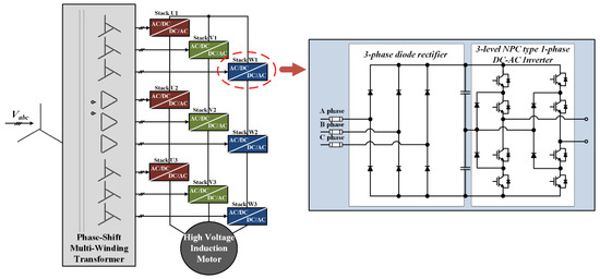
Figure 1.
Configuration of 13-level cascaded NPC/h-bridge system with diode rectifier.
To solve out the problem, a phase shifting transformer is usually employed at the secondary side of the main transformer, however, it causes the system to be more complicated, and increases the cost and volume as well. For further improvement of those factors mentioned previously, the CNHB is usually used as an active front end (AFE) including regenerative capability, instead of the conventional rectifier. This CNHB allows regenerative energy to be transferred from a load side to the input source, grid etc., and power factor (PF) of each cell to be well controlled as shown in Figure 2 [7,8,9].
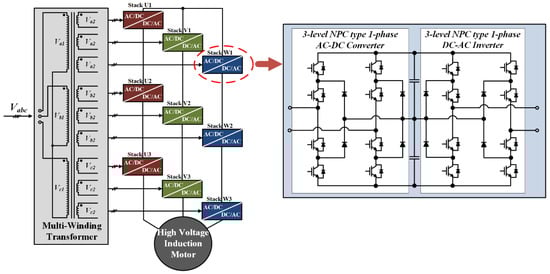
Figure 2.
Configuration of 13-level cascaded NPC/h-bridge inverter with single-phase AFE rectifier.
However, as can be seen in Figure 2, since one cell has a single-phase NPC/h-bridge (NHB) connected in series, voltage fluctuation with twice the frequency of the input source inevitably occurs in the dc-link of each cell so that an additional circuit is needed to eliminate it. Moreover, the component with twice the inverter output frequency in each cell produces voltage fluctuation of the dc-link, and even deteriorates the PF.
To solve those problems, the conventional approach [10] proposes a six-switch single-phase AC/DC/AC converter with two semiconductor switches removed from the h-bridge topology. However, it can be used only in stand-alone single-phase AC/DC/AC systems not in multi-level systems. Also literature [11] proposes a current harmonics injection method to reduce the voltage fluctuation of the dc-link. Current harmonics injection method results in aggravation of the THD characteristic of the inverter output current and it means that trade-off between inverter output current and dc-link capacitance should be considered for appropriate control objective.
Therefore, in this paper, a control method based on new adaptive filters is proposed to reduce the voltage fluctuation and improve PF and current harmonics without additional sacrifice unlike the conventional methods. Additionally, the voltage fluctuation of dc-link affected by input and output frequency in a cell of CNHB is theoretically analyzed.
This paper is organized as follows: Section 2 theoretically analyzes the components with specific harmonic current contents affecting dc-link voltage fluctuations by the input and output frequency, and introduces design of the dc-link capacitor through system modeling. Section 3 describes the conventional filter for reducing the dc-link variance component and introduces the proposed adaptive filter. Section 4 and Section 5 give the simulation and experimental results for validation of the proposed control method based on the adaptive filter; and Section 6 provides the conclusion.
2. Analysis of the DC-Link in the CNHB System
The CNHB topology consists of a plurality of converters and inverters, which are connected in series. One cell consists of a converter and an inverter, which includes two dc-link capacitors, eight switches and four clamping diodes [12]. Figure 1 shows that the diode rectifier is replaced with a converter, which has the advantage to control selectively current harmonic contents or replacement angle between the input voltage and current. It is also possible to utilize a general transformer or a multi winding transformer, instead of a complex phase shifting transformer, thereby reducing the volume and cost of the transformer in the system.
However, since the converter of each cell is connected to the single-phase transformer as shown in Figure 3, the voltage fluctuation in the dc-link capacitor can be caused by both of the input power and load. As can be seen Figure 3, the specific harmonic components are generated in the dc-link capacitor. Meanwhile, the specific harmonic components are composed of the amount of voltage fluctuations generated by each frequency of the input side of the converter and the output side of the inverter [13]. This requires large dc-link capacitance, and in addition, adversely affects the durability and increases the overall volume of the system. These are the drawbacks of the system. Therefore, theoretical analysis of these harmonic components is needed.
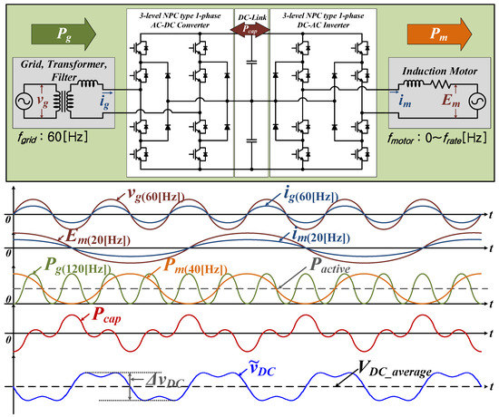
Figure 3.
Characteristics of dc-link voltage fluctuation by the input and output power in shingle phase NHB.
2.1. Voltage Fluctuation Analysis in the DC-Link of One Cell
The frequency of the input voltage is usually fixed at (50 or 60) Hz. Also, if the PF control of the grid is normally performed using the current controller of the NHB converter, the phase of input voltage and current is in-phase, as shown in Figure 3. The input voltage and current of the converter and the power of the converter can be expressed by Equations (1)–(3):
where, and are the maximum values of input voltage and current, respectively; is the angular speed of the input voltage; is the phase angle of the input voltage; and is the displacement angle of and . Meanwhile, can be defined as the PF, because and are pure sinusoidal waveform, and the product of and in this single-phase system is divided into the active power component and reactive power component vibrating at twice the frequency of the input voltage by .
The output voltage and current of the inverter, and consequently the power, are represented as follows:
where, and are the maximum output voltage and current of the inverter, is the angular speed of the output voltage of the inverter, is the phase angle of the inverter output, and is the phase difference between the output voltage and current of the inverter. Equations (4)–(6) are also divided into the active power components expressed with a part of PF , and the reactive power component oscillated with twice the output voltage frequency of the inverter expressed with a part of :
Assuming that PF is well controlled using the current controller of the NHB converter, the NHB converter receives as much power as the power consumed by the inverter, in order to control the dc-link voltage to the reference voltage. However, if the output voltage frequency of the inverter differs from the input voltage frequency of the converter, a fluctuation may occur in the dc-link voltage, due to the difference between the oscillated reactive power components in Equations (3) and (6). Those components are presented in Equation (7).
In order to control the dc-link voltage by the reference voltage, the NHB converter receives as much power from the input source as the active power required by the inverter. Therefore, and can be expressed as Equation (8) using and :
By substituting (7) with (8), the instantaneous power on the dc-link capacitor can be defined as follows:
Equation (9) implies that if the frequency of the input voltage is different from the output voltage frequency of inverter, fluctuation of power can be generated in the dc-link. The dc-link current and voltage that can be generated by this power can be expressed as Equations (10) and (11):
If the frequency of the input voltage differs from the output voltage frequency of the inverter, as shown in Equation (11), the frequency of the dc-link voltage fluctuation is twice as large as either the output voltage frequency of the inverter, or the frequency of the input voltage. These two components eventually cause a voltage fluctuation of the dc-link capacitor.
2.2. Optimal Designing DC-Link Capacitor
Figure 4, Figure 5, Figure 6 and Figure 7 show the voltage fluctuation in the dc-link when the output voltage frequency of the inverter is different, using the Equation (11). In Figure 4, Figure 5, Figure 6 and Figure 7, dc-link voltage is 120 Vdc, capacitance of dc-link is 4.5 mF, is 89.81 Vpeak, is 2.1 rad/s, is 0 rad/s, is 377 rad/s and magnitude of and are changed by V/f control. Each figure shows the dc-link voltage for the three cells making up the U phase of the inverter. When the output voltage frequency of the inverter is low as shown in Figure 4 and Figure 5, the harmonic component’s frequency is twice the output voltage frequency of the inverter, which is composed of the 120 Hz harmonic component, which is twice the input voltage frequency. These cause the voltage fluctuation of the dc-link.
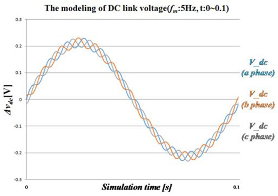
Figure 4.
Modeling of the dc-link voltage fluctuation depending on the output voltage frequency of the inverter at .
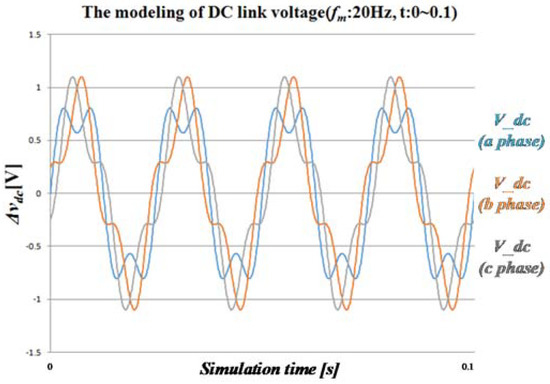
Figure 5.
Modeling of the dc-link voltage fluctuation depending on the output voltage frequency of the inverter at .
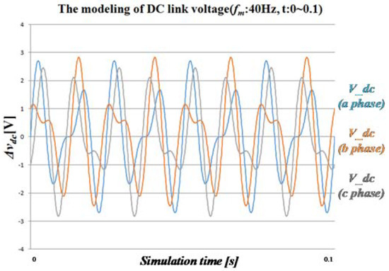
Figure 6.
Modeling of the dc-link voltage fluctuation depending on the output voltage frequency of the inverter at .
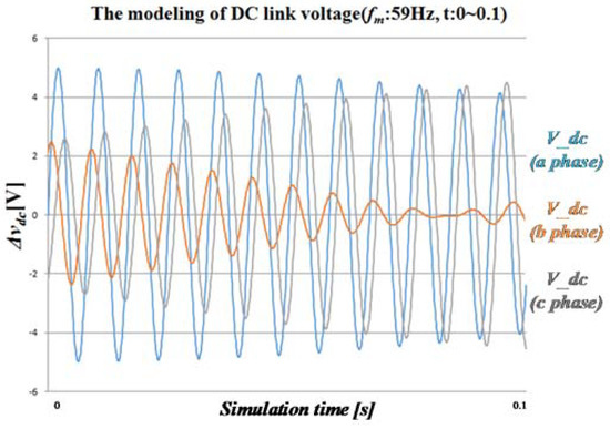
Figure 7.
Modeling of the dc-link voltage fluctuation depending on the output voltage frequency of the inverter at .
However, as the output voltage frequency of the inverter increases, different amplitude, phase, and ripple voltages can be generated in each cell, as shown in Figure 6. As the frequency of the inverter output voltage becomes closer to the frequency of the input voltage, the more similar to a sine waveform that 120 Hz component is multiplied by the low frequency sine wave, as shown in Figure 7.
Thus, the maximum value of the voltage ripple is an important factor to be considered in the design of the system, because voltage fluctuation appearing in the dc-link can vary the maximum value of the amplitude for each cell.
In Equation (11), the formula outside of the curly bracket is already fixed, or it is a controlled constant value, while the expression inside the bracket has different values over time, but does not exceed the maximum and minimum values of sine and cosine, ±1. Therefore, the time when the voltage of the dc-link reaches the maximum can be defined by Equation (12), and voltage of dc-link becomes minimum can be expressed as Equation (13):
In order to calculate voltage fluctuation simplify, power factor and is assumed as 1. By subtracting the minimum voltage from the maximum voltage of the dc-link capacitor, the voltage fluctuation of the dc-link can be defined as Equation (14) using the Equations (12) and (13):
Also, Equation (14) can be rearranged with , as follows:
Thus, dc-link capacitors can be designed by selecting the maximum ripple voltage and substituting parameters used in the system.
3. Proposed Control Method Using Adaptive Filters
3.1. Conventional Filter
Control characteristics of multilevel systems connecting with the grid have significant effects on the input PF and voltage fluctuation of the dc-link capacitor. In implementing the controller, various types of filters have been proposed to prevent unreliable control due to noise of the peripheral circuit while eliminating specific harmonics [14,15,16]. Conventional filters typically include notch filter (NF), band pass filter (BPF) and low pass filter (LPF). Among many types of conventional filters, NF has been widely used in industrial field. By analyzing transfer function and characteristic of NF, it is possible to apply it to obtain reliable control.
NF is a filter that can remove only desired harmonic components. NF has been studied for controlling ripple component caused by second order harmonic component in various types of topology [17,18,19,20,21,22,23]. Figure 8 shows an equivalent circuit, block diagram and transfer function of an NF. From the equivalent circuit of NF, a transfer function of the NF can be defined as follows:
where and .
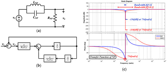
Figure 8.
Characteristics and configuration of NF (a) Equivalent circuit, (b) Block diagram, (c) Bode plot of NF various Q-factor.
Using Equation (16), a block diagram and bode plot of NF can be drawn as shown in Figure 8b,c. The transfer function of NF is composed of as center frequency and Q as Q-factor based on passive elements.
Figure 8c shows the magnitude and phase response characteristics of NFs as bode plot. Attenuation occurs at the center frequency so that only harmonic component corresponding to the center frequency is blocked while output voltage vo is generated by input voltage vi of the NF without harmonic component. In addition, bandwidth and magnitude of attenuation are adjusted by Q. With increasing Q, bandwidth becomes smaller, which allows NF strongly removing harmonic components placing at the center frequency.
3.2. Proposed Adaptive Filters and Control Method
Conventional filter discussed in previous Section 3.1 have fixed cut-off frequency or center frequency. Therefore, adaptive filters have been proposed so that the frequency of harmonic components can vary every time due to change of system frequency [24,25,26,27]. In this paper, series notch filter (SNF) and decoupled band pass filter (DBPF) are proposed as adaptive filters. This subsection discusses theoretical analysis of proposed filters to eliminate voltage fluctuation that occurs in the dc-link capacitor described in Section 2, and improve PF of the input side.
3.2.1. Series Notch Filter
Figure 9 shows a block diagram of SNF where two NFs are connected in series.
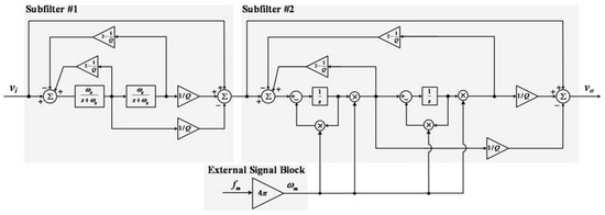
Figure 9.
Block diagram of SNF.
Unlike conventional NF, SNF is used to eliminate two harmonic components of input voltage . SNF is composed of two subfilters. Each subfilter is based on conventional NF. Subfilter #1 only removes harmonic component at fixed frequency while subfilter #2 is used to eliminate harmonic components even if their frequency is changed. Difference between subfilter #1 and subfilter #2 is that subfilter #2 is connected with an external signal block. Center frequency of subfilter #2 is changed by variable external signal from the external signal block. Adjusted center frequency changes parameter of subfilter #2 to remove variable harmonic components. As a result, one of fixed harmonic component in input voltage is eliminated by subfilter #1. A another variable harmonic component in output of subfilter #1 is then removed in adjustable subfilter #2.
From the transfer function of NF and block diagram of SNF, a total transfer function of the SNF can be defined with Equation (17):
where and .
As shown in Equation (17), the center frequency of subfilter #1 is set at 754 rad/s for removing harmonic components corresponding twice to frequency of input voltage which is 60 Hz in this paper. Another harmonic component can be filtered at subfilter #2 where center frequency is changed by corresponding twice to variable frequency . Center frequency of subfilter #2 is adjusted by external signal so that the proposed SNF not only removes fixed harmonic component, but also adjusts to eliminate variable harmonic components.
The SNF transfer function has two bandwidths, denoted Bg and Bm. These can be defined by using each Q-factor and center frequency as follows:
The magnitude and phase response characteristics of the SNF are shown in Figure 10 using bode plot. When SNF has fixed center frequency at 754 rad/s, red dotted line is set by external signal at 503 rad/s while, blue line is set by changed external signal at 628 rad/s. Magnitude of red dotted line is −125 dB at 503 rad/s while magnitude of blue line is −123 dB at 628 rad/s (−122 dB of attenuation at 754 rad/s in both cases). It shows that as changes, attenuation occurs in the corresponding center frequency while variable harmonic components can be eliminated by adjusting center frequency of SNF.
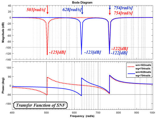
Figure 10.
Bode plot of SNF various central frequency.
3.2.2. Decoupled Band Pass Filter
Another adaptive filter DBPF is proposed in this paper. Figure 11 illustrates block diagram of DBPF where two conventional BPFs are connected in parallel. To remove two harmonic components of input voltage , each subfilter extracts different harmonic components from input voltage . Subfilter #1 only extracts harmonic components at fixed frequency while subfilter #2 extracts variable harmonic components. The extraction frequency area of subfilter #2 can be changed since center frequency of subfilter #2 comes from the external signal block. Therefore, output of two subfilters becomes harmonic components of input voltage. DBPF subtracts output of two subfilters from input voltage so that two harmonic components in input voltage can be removed. The DBPF can have better characteristic of filtering than conventional BPFs since harmonics component is eliminated by decoupling frequency areas where each output of subfilter overlaps with one another. From the transfer function of BPF and block diagram of DBPF, a total transfer function of the DBPF can be defined as follows:
where and .
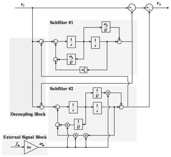
Figure 11.
Block diagram of DBPF.
The center frequency of subfilter #1 is defined at 754 rad/s for removing one of fixed harmonic components, derived from frequency of input voltage. is changed by external signal, corresponding twice to variable frequency . Because of decoupling block of DBPF, difference between transfer function of SNF and DBPF is that second order term of denominator in transfer function of DBPF is simpler than that of SNF.
DBPF also has two bandwidths expressed as Bg and Bm. It can be defined as follows:
Figure 12 shows magnitude and phase response characteristics of DBPF using a Bode plot. When DBPF has fixed center frequency at 754 rad/s, red dotted line is set by external signal at 503 rad/s and blue line is set by changed external signal at 628 rad/s. Magnitude of red dotted line is −125 dB at 503 rad/s while magnitude of blue line is −123 dB at 628 rad/s (−122 dB of attenuation at 754 rad/s in both cases). As center frequencies of the DBPF change according to the external signals, gain is attenuated in the corresponding frequency. This confirms that magnitude is attenuated in the corresponding frequency as changes.
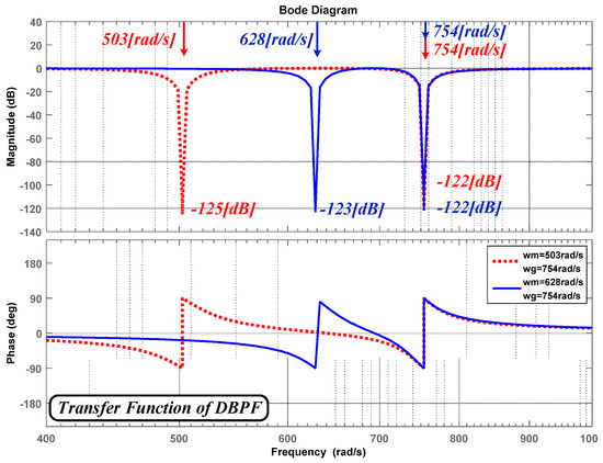
Figure 12.
Bode plot of DBPF various center frequency.
Figure 13 illustrates magnitude and phase response characteristics of two proposed adaptive filters, SNF and DBPF, using a Bode plot. Applied conditions are: bandwidth Qg = Qm = 10; center frequency = 691 rad/s, = 754 rad/s in each filter. As can be seen in Figure 13, magnitude characteristics of SNF and DBPF are almost the same (−123 dB at 628 rad/s and −122 dB at 786 rad/s, respectively).
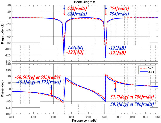
Figure 13.
Comparison of SNF and DBPF in bode plot.
Phase shift characteristics can be estimated by comparing each phase at gain of −3 dB in the Bode plot. It means that how many phase delays have occurred by phase response characteristic of filter. Phase shift characteristic of each filter illustrated in Figure 13 shows that DBPF has 50.8 degrees at 786 rad/s while SNF has 57.7 degrees at 786 rad/s. As shown in Figure 13, SNF and DBPF have similar magnitude characteristic. Since mutual interference components of subfilter #1 and subfilter #2 are decoupled, phase delay of DPBF is less than that of SNF. As a result, DBPF shows better phase response characteristic than SNF.
3.2.3. Control Method
Figure 14 shows a control block diagram of the conventional method for a one NPC/h-bridge converter cell. In this case, the voltage controller is affected by voltage fluctuation and harmonic components in the dc-link. In addition, the output signal of PI voltage controller is included in the harmonic components. Thus, current control is distorted since the input reference of current controller comes from the output of voltage controller included in the harmonic components.
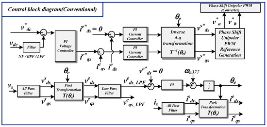
Figure 14.
Conventional control block diagram of NPC/h-bridge converter.
To overcome the disadvantage of the conventional control method due to voltage fluctuation and harmonic components in the dc-link, the control block diagram with an adaptive filter is proposed for a one NPC/h-bridge converter cell as shown in Figure 15.
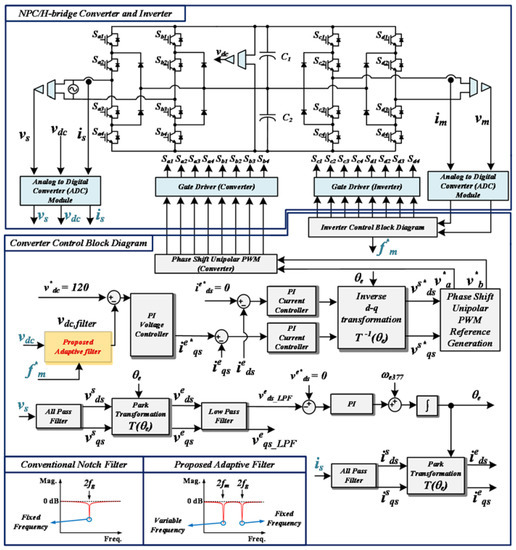
Figure 15.
Proposed control block diagram of NPC/h-bridge converter with new adaptive filters.
When a voltage controller is used to control the voltage of the dc-link, the actual voltage in the dc-link is used as an input to the proposed adaptive filter to eliminate harmonic components. At this time, the frequency of output voltage is given through DSP of the inverter so that adaptive filter can set their center frequency as twice of the frequency of the output voltage of inverter.
Therefore, harmonic components in the dc-link corresponding to twice the input voltage of converter and output voltage of inverter can be removed by the adaptive filter. The output of the adaptive filter is used as a feedback signal to the voltage controller to perform dc-link voltage control without harmonic components. Since the voltage controller can operate without harmonics, the current controller is not affected by harmonics from dc-link voltage fluctuation as described in Section 2. With these procedures, the proposed control scheme with adaptive filter can reduce dc-link voltage fluctuations and improve the power factor.
4. Simulation Results
In order to verify principle and feasibility of the proposed control method based on adaptive filters, the simulation has been developed using the PSIM software program. The simulation schematic in which the 13-level cascaded NPC/h-bridge is connected to the grid is illustrated in Figure 2. The systems parameters of the simulation and experiment are shown in Table 1.

Table 1.
Simulation and experiment parameters.
Figure 16 shows a simulation waveform with one ac/dc converter and an inverter driven by applying the conventional control method consisting of a 120 Hz notch filter to the dc-link feedback, as introduced in Section 3.1 [28,29]. Before applying the existing control, the initial charge of the dc-link is performed through the ramp function, and when the steady state is reached, the dc-link voltage control is performed through the conventional control method with notch filter. The output voltage of the inverter is controlled by V/F control, at that time the frequency of the inverter output voltage is approximately 56.67 Hz. Figure 17 shows the steady-state result of Figure 16 in an enlarged view of time. As shown in Figure 17e, the output current of the inverter is close to a sinusoidal wave.
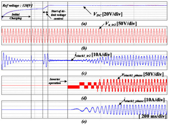
Figure 16.
Simulation results of the conventional control method applied in the single-phase NPC/h-bridge converter (a) dc-link voltage, (b) input voltage of the converter, (c) input current of the converter, (d) output voltage of the inverter, (e) output current of the inverter (200 ms/div).
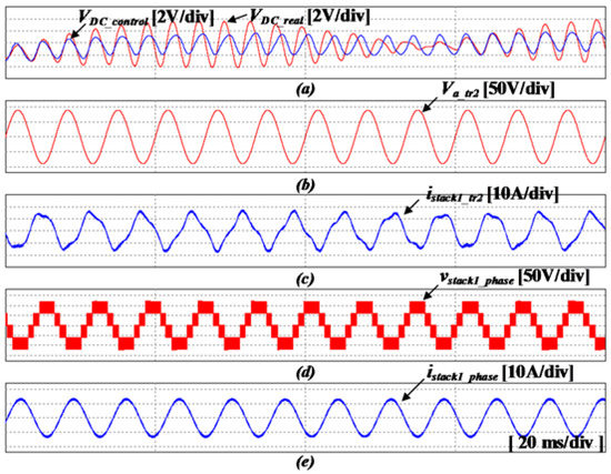
Figure 17.
Simulation results of the conventional control method applied in the single-phase NPC/h-bridge converter (a) dc-link voltage, (b) input voltage of the converter, (c) input current of the converter, (d) output voltage of the inverter, (e) output current of the inverter (20 ms/div).
However, it can be seen that many harmonics are mixed in the input current as shown in Figure 17c. As shown in Figure 17a, using the conventional control method, voltage control is performed except for the 120 Hz component in the actual voltage component of the dc-link. Therefore, the voltage controller of the dc-link transfers the components of the specific frequency which are lower than 120 Hz to the input of the current controller. As a result, it generates harmonics in the input current and the effect of decreasing the dc-link voltage fluctuation is also insufficient.
Figure 18 shows the fast Fourier transform (FFT) waveforms for the waveforms in Figure 17. The 120 Hz ripple voltage component in the actual dc-link voltage is removed by the notch filter of the conventional control method configured in the input to the voltage controller. However, the component of 113.33 Hz which is twice the output frequency of the inverter, 56.67 Hz, is not removed, and flows into the voltage controller. Therefore, when the output value of the current controller is performed in reverse d-q transform, this harmonic component is shown as a harmonic component of 173.33 Hz. This harmonic component is converted to a power ripple of 233.33 Hz by a 60 Hz input voltage, causing a voltage fluctuation in the dc-link, and this fluctuation generates current component of 303.33 Hz in the input current again.
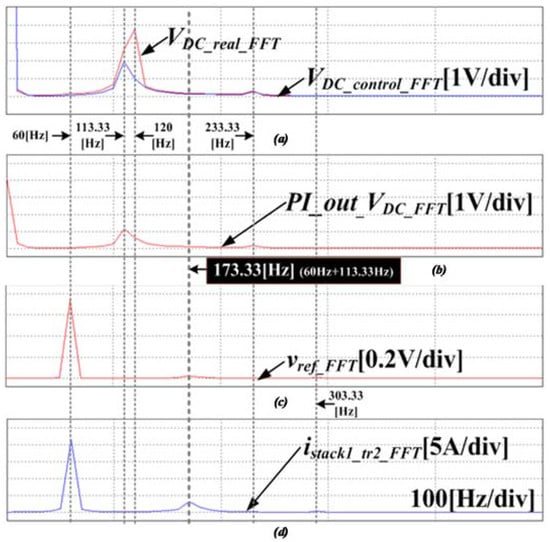
Figure 18.
FFT simulation results of the conventional control method applied in the single-phase NPC/h-bridge converter (a) actual dc-link voltage and output signal of the NF, (b) output signal of the PI voltage controller, (c) reference voltage of the dc-link, (d) input current of the converter.
Figure 19 shows the result of simulations using the SNF adaptive filter, which is one of the proposed control method. As shown in Figure 19c, when the simulation is performed under the same conditions as in the conventional control described above, it can be seen that the input current is close to a sinusoidal wave. The steady-state result waveform is shown in Figure 20. By removing the dc-link fluctuation component through the SNF, and then performing the voltage control, the voltage fluctuation of the dc-link and the PF of the input current are clearly better than those of the conventional control. Figure 21 shows the FFT analysis of the waveforms in Figure 20. As shown in Figure 21, in the proposed control, since the output frequency component and the 120 Hz component of the inverter are not shown when the dc-link voltage is feedback, it can be confirmed that only the dc component exists in the output of the voltage controller.
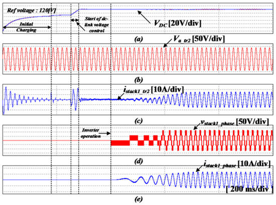
Figure 19.
Simulation results using the proposed control method with the SNF adaptive filter. (a) dc-link voltage, (b) input voltage of the converter, (c) input current of the converter, (d) output voltage of the inverter, (e) output current of the inverter (200 ms/div).
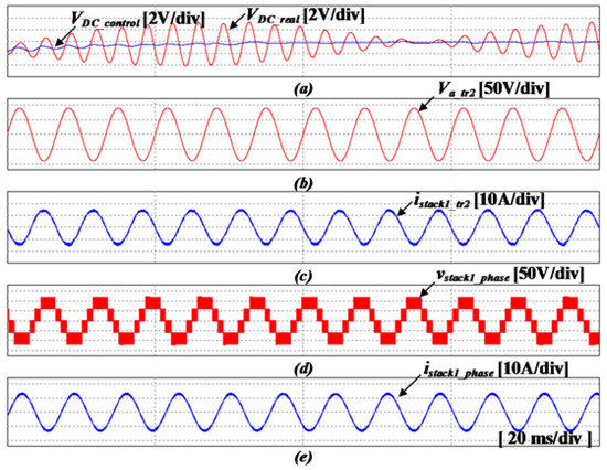
Figure 20.
Simulation results using the proposed control method with the SNF adaptive filter. (a) dc-link voltage, (b) input voltage of the converter, (c) input current of the converter, (d) output voltage of the inverter, (e) output current of the inverter (20 ms/div).
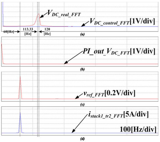
Figure 21.
FFT simulation results using the proposed control method with the SNF adaptive filter. (a) actual dc-link voltage and output signal of the SNF, (b) output signal of the PI voltage controller, (c) reference voltage of the dc-link, (d) input current of the converter.
Figure 22, Figure 23 and Figure 24 show the simulation result waveform with the DBPF adaptive filter applied. This was performed under the same conditions as the simulations mentioned above. DBPF also has characteristics similar to the steady state waveform using SNF, because it forms a notch angle for two frequencies in the same way as SNF. In addition, since the voltage control is performed using only the dc component, excluding the voltage fluctuation component generated in the dc-link, the harmonics mixed in the input current are reduced, and the voltage fluctuation of the dc-link is also decreased.
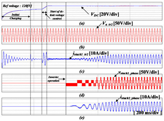
Figure 22.
Simulation results using the proposed control method with the DBPF adaptive filter. (a) dc-link voltage, (b) input voltage of the converter, (c) input current of the converter, (d) output voltage of the inverter, (e) output current of the inverter (200 ms/div).
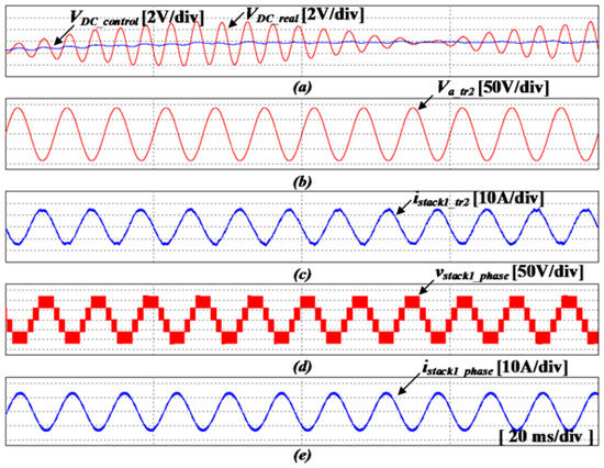
Figure 23.
Simulation results using the proposed control method with the DBPF adaptive filter. (a) dc-link voltage, (b) input voltage of the converter, (c) input current of the converter, (d) output voltage of the inverter, (e) output current of the inverter (20 ms/div).
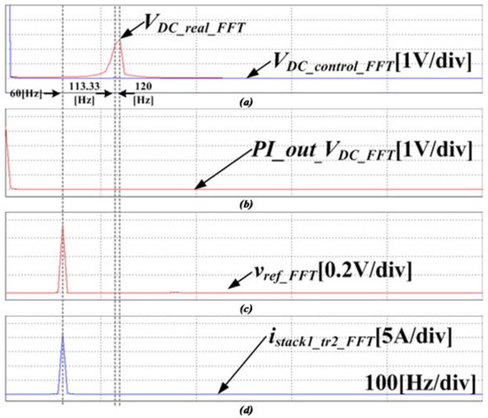
Figure 24.
FFT simulation results using the proposed control method with the DBPF adaptive filter. (a) actual dc-link voltage and output signal of the DBPF, (b) output signal of the PI voltage controller, (c) reference voltage of the dc-link, (d) input current of the converter.
Simulation results of conventional NF, proposed SNF and DBPF applied in single-phase NPC/h-bridge converter are analyzed by comparing characteristics of dc-link voltage, THD and power factor of input current as shown in Table 2. The proposed SNF shows superior reduction of voltage fluctuation as 10.9 V. Furthermore, voltage fluctuation of the proposed DBPF is 10.9 V, which is smaller than the 11.4 V of the conventional NF. The characteristic of the THD is improved by proposed control method, which is 2.38% in SNF and 2.36% in DBPF. Compared to conventional control method with NF, proposed SNF and DBPF has better power factor, which is 0.99 in SNF and DBPF. As a result, proposed control method with two adaptive filters not only reduces the dc-link voltage fluctuation, but also improves the characteristics of THD and power factor of input current.
Table 2.
Comparison of the characteristics of the ac/dc converter for different control methods.
5. Experiment Results
An experiment was performed to verify the feasibility of the proposed control method applied in a cascaded NPC/h-bridge system. The configurations of the experimental system and power stacks are as follows Figure 25, Figure 26, Figure 27 and Figure 28, and the experimental parameters as in Table 1.
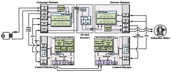
Figure 25.
Configuration of the experiment system.

Figure 26.
Experimental setup 1 of the 13-level cascaded NPC/h-bridge system.
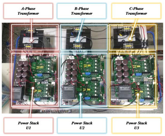
Figure 27.
Experimental setup 2 of the 13-level cascaded NPC/h-bridge system.
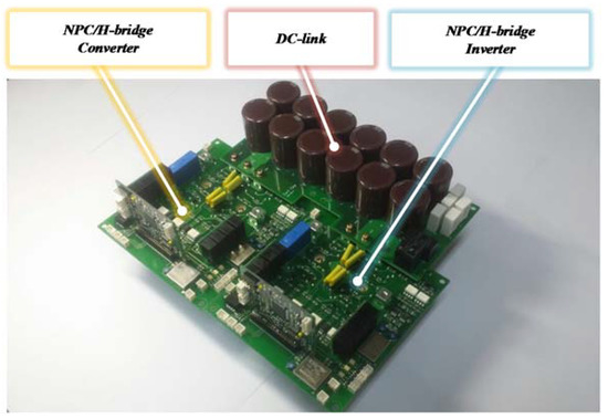
Figure 28.
Experimental setup 3 of the one-stack NPC/h-bridge.
The controller is implemented on TMS320F28377s, and that of the floating point microcontroller unit at 200 MHz rate frequency. The switching and sampling frequency is 10 kHz. The power is supplied to the cascaded NPC/h-bridge inverter through the cascaded NPC/h-bridge converter.
Figure 29 shows the output phase voltage waveforms on phase a, b, and c for the phase shift PWM (PS-PWM) scheme applied to a 13-level cascaded NPC/H-bridge system. As one can see in Figure 29, the output voltage of step 13 appears. Figure 30 shows a slightly enlarged view of each phase. Since PS-PWM is implemented as a unipolar PWM scheme, the inverter stack of each cell is modulated through a carrier whose output voltage is divided into five stages, and each stack is phase shifted by 120°. Thus, each phase can obtain an output voltage in 13 steps.
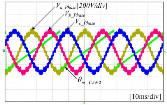
Figure 29.
Waveforms of each phase voltage of the inverter.
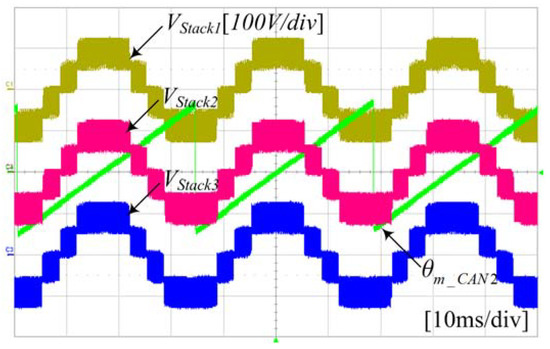
Figure 30.
Waveforms of the phase voltage of each cell in a-phase.
Figure 31 shows the experimental waveform of the dc-link voltage of the single-phase NPC/h-bridge converter, the output voltage of the inverter, the input side system current, and the inverter output current. After the initial charge sequence was performed, the dc-link voltage was controlled to reach the steady state, and the inverter was driven.
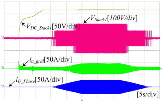
Figure 31.
Waveforms of the singe-phase NPC/h-bridge converter operation using the proposed control method.
Figure 32, Figure 33 and Figure 34 shows the dc-link ripple waveform when the control sequence of Figure 31 reaches steady state by applying the proposed control. The inverter power frequencies of (20, 40, and 56.67) Hz are applied, respectively. Simulation results show that ripple voltage corresponding to twice the output voltage frequency of the inverter, and ripple voltage corresponding to twice the system voltage frequency are generated in the dc-link like the waveform. The components that fluctuate the voltage of the dc-link are extracted according to the frequency through the proposed filter, and removed when performing the voltage control, thereby reducing the power factor of the input side system current, and the ripple of the dc-link.
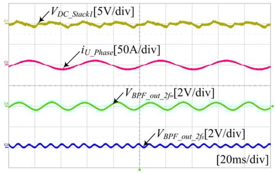
Figure 32.
Waveform of the voltage fluctuation in the dc-link. (Output frequency of inverter at 20 Hz).
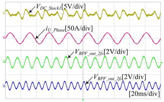
Figure 33.
Waveform of the voltage fluctuation in the dc-link. (Output frequency of inverter at 40 Hz).
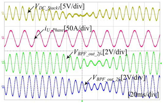
Figure 34.
Waveform of the voltage fluctuation in the dc-link. (Output frequency of inverter at 56.67 Hz).
6. Conclusions
This paper proposed new adaptive filters for the 13-level cascaded NPC/h-bridge systems. It can reduce the voltage fluctuation at the dc-link capacitor and improve current harmonic distortion and PF as well in the system.
Theoretical analysis of the NPC/h-bridge system discovered voltage fluctuation component by the input side of the converter and the output side of the inverter. In addition, a dc-link capacitor design considering these components was described.
Conventional filter, such as the NF was analyzed its magnitude and phase response characteristic. Unlike the conventional filter to extract the harmonic components at the fixed-frequency region, the proposed adaptive filters have the advantage of reducing two harmonic components at the variable-frequency region. Two proposed adaptive filters, SNF and DBPF are introduced, and applied to the proposed control method.
In this paper, simulation and experiment were performed and presented to verify the proposed filters and control method as well as their feasibility. From them, the proposed method resulted in better performance of smaller dc-link voltage fluctuation and lower current harmonic distortion. The voltage regulation can be reduced from 9.6% to 9.1%, and the THD of the input current is drastically reduced from about 17.03% to about 2.4%. Given the results, it is expected that the proposed control method with adaptive filter is one of good candidates for multi-level cascaded NPC/h-bridge systems.
Author Contributions
Jin-Wook Kang and Seung-Wook Hyun conceived and designed the experiment; Jintae Kim, Seung-Wook Hyun and Hoon Lee performed the experiment; Jin-Wook Kang and Hoon Lee analyzed the theory. Jintae Kim and Hoon Lee wrote the manuscript. Jintae Kim and Chung-Yuen Won participated in research plan development and revised the manuscript. All authors have contributed to the manuscript.
Acknowledgments
This work was supported by the Korea Institute of Energy Technology Evaluation and Planning (KETEP) and the Ministry of Trade, Industry & Energy (MOTIE) of the Republic of Korea. (Nos. 20152020105720, 20162010103830).
Conflicts of Interest
The authors declare no conflict of interest.
References
- Ying, J.; Gan, H. High power conversion technologies and trend. In Proceedings of the 2012 7th International Power Electronics and Motion Control Conference (IPEMC), Harbin, China, 2–5 June 2012; pp. 1766–1770. [Google Scholar]
- Marzoughi, A.; Burgos, R.; Boroyevich, D.; Xue, Y. Investigation and comparison of cascaded H-bridge and modular multilevel converter topologies for medium-voltage drive application. In Proceedings of the 40th Annual Conference of IEEE Industrial Electronics Society-IECON, Dallas, TX, USA, 29 October–1 November 2014; pp. 1562–1568. [Google Scholar]
- Qashqai, P.; Sheikholeslami, A.; Vahedi, H.; Al-Haddad, K. A review on multilevel converter topologies for electric transportation applications. In Proceedings of the IEEE-Vehicular Power and Propulsion Conference, Montréal, QC, Canada, 19–22 October 2015; pp. 1–6. [Google Scholar]
- Marzoughi, A.; Burgos, R.; Boroyevich, D.; Xue, Y. Design and Comparison of Cascaded H-Bridge, Modular Multilevel Converter, and 5-L Active Neutral Point Clamped Topologies for Motor Drive Applications. IEEE Trans. Ind. Appl. 2018, 54, 1404–1413. [Google Scholar] [CrossRef]
- Song, Z.; Tian, Y.; Yan, Z.; Chen, Z. Direct power control for three-phase two-level voltage-source rectifiers based on extended-state observation. IEEE Trans. Ind. Electron. 2016, 63, 4593–4603. [Google Scholar] [CrossRef]
- Hammond, P. A new approach to enhance power quality for medium voltage ac drives. IEEE Trans. Ind. Appl. 1997, 33, 202–208. [Google Scholar] [CrossRef]
- Sau, S.; Karmakar, S.; Fernandes, B.G. Modular Transformer-Based Regenerative-Cascaded Multicell Converter for Drives with Multilevel Voltage Operation at Both Input and Output Sides. IEEE Trans. Ind. Electron. 2018, 65, 5313–5323. [Google Scholar] [CrossRef]
- Malinowski, M.; Gopakumar, K.; Rodriguez, J.; Perez, M.A. A survey on cascaded multilevel inverters. IEEE Trans. Ind. Electron. 2010, 57, 2197–2206. [Google Scholar] [CrossRef]
- Ramírez, R.; Espinoza, J.; Baier, C. Operating region of a power cell in a CHB based topology operating at reduced second harmonic. In Proceedings of the 42nd Annual Conference of the IEEE Industrial Electronics Society, Florence, Italy, 23–26 October 2016; pp. 5058–5063. [Google Scholar]
- Liu, X.; Wang, P.; Loh, P.C.; Blaabjerg, F.; Xue, M. Six switches solution for single-phase AC/DC/AC converter with capability of second-order power mitigation in DC-link capacitor. In Proceedings of the Energy Conversion Congress and Exposition (ECCE), Phoenix, AZ, USA, 17–22 September 2011; pp. 1368–1375. [Google Scholar]
- Engel, S.P.; De Doncker, R.W. Control of the Modular Multi-Level Converter for minimized cell capacitance. In Proceedings of the 14th European Conference on Power Electronics and Applications (EPE 2011), Birmingham, UK, 30 August–1 September 2011; pp. 1–10. [Google Scholar]
- Kim, M.N.; Noh, Y.S.; Kim, J.G.; Jung, Y.C.; Won, C.Y. Active power decoupling using bi-directional resonant converter for flyback inverter without electrolytic capacitor of PV AC module system. In Proceedings of the International Conference on Electrical Machines and Systems, Busan, Korea, 26–29 October 2013; pp. 351–356. [Google Scholar]
- Zhu, G.R.; Tan, S.C.; Chen, Y.; Tse, C.K. Mitigation of Low-Frequency Current Ripple in Fuel-Cell Inverter Systems through Waveform Control. IEEE Trans. Power Electron. 2013, 28, 779–792. [Google Scholar] [CrossRef]
- Narayanasamy, B.; Luo, F.; Chu, Y. High density EMI mitigation solution using active approaches. In Proceedings of the IEEE International Symposium on Electromagnetic Compatibility & Signal/Power Integrity (EMCSI 2017), Washington, DC, USA, 7–11 August 2017; pp. 813–818. [Google Scholar]
- Zhao, H.; Wang, S.; Moeini, A.; Yang, L. Investigation of CCL filter for multilevel selective compensation (SHC) with staircase modulation. In Proceedings of the IEEE Energy Conversion Congress and Exposition (ECCE), Cincinnati, OH, USA, 1–5 October 2017; pp. 5206–5213. [Google Scholar]
- Peña-Alzola, R.; Campos-Gaona, D.; Ksiazek, P.F.; Ordonez, M. DC-Link Control Filtering Options for Torque Ripple Reduction in Low-Power Wind Turbines. IEEE Trans. Power Electron. 2017, 32, 4812–4826. [Google Scholar] [CrossRef]
- Sha, D.; Xu, Y.; Zhang, J.; Yan, Y. Current-Fed Hybrid Dual Active Bridge DC–DC Converter for a Fuel Cell Power Conditioning System with Reduced Input Current Ripple. IEEE Trans. Ind. Electron. 2017, 64, 6628–6638. [Google Scholar] [CrossRef]
- Zhao, W.; Ruan, X.; Yang, D.; Chen, X.; Jia, L. Neutral Point Voltage Ripple Suppression for a Three-Phase Four-Wire Inverter with an Independently Controlled Neutral Module. IEEE Trans. Ind. Electron. 2017, 64, 2608–2619. [Google Scholar] [CrossRef]
- Ghartemani, M.K.; Khajehoddin, S.A.; Jain, P.K.; Bakhshai, A.; Mojiri, M. Addressing DC component in PLL and notch filter algorithms. IEEE Trans. Power Electron. 2012, 27, 78–86. [Google Scholar] [CrossRef]
- Trinh, Q.N.; Wang, P.; Tang, Y.L.; Koh, H.; Choo, F.H. Compensation of DC Offset and Scaling Errors in Voltage and Current Measurements of Three-Phase AC/DC Converters. IEEE Trans. Power Electron. 2018, 33, 5401–5414. [Google Scholar] [CrossRef]
- Karimi-Ghartemani, M.; Mojiri, M.; Safaee, A.; Walseth, J.A.; Khajehoddin, S.A.; Jain, P.; Bakhshai, A. A New Phase-Locked Loop System for Three-Phase Applications. IEEE Trans. Power Electron. 2013, 28, 1208–1218. [Google Scholar] [CrossRef]
- Wu, F.; Sun, D.; Duan, J. Diagnosis of single-phase open-line fault in three-phase PWM rectifier with LCL filter. IET Gener. Trans. Distrib. 2016, 10, 1410–1421. [Google Scholar] [CrossRef]
- Hansen, A.D.; Michalke, G. Modelling and control of variable-speed multi-pole permanent magnet synchronous generator wind turbine. Wind Energy 2008, 11, 537–554. [Google Scholar] [CrossRef]
- Zhu, C.; Zeng, Z.; Zhao, R. Adaptive suppression method for DC-link voltage offset in three-phase four-switch inverter-fed PMSM drives. IET Electron. Lett. 2016, 52, 1442–1444. [Google Scholar] [CrossRef]
- Zhao, Z. Adaptive internal model control based ripple rejection for improved response of PFC rectifiers. In Proceedings of the 30th Annual Conference on Electrical and Computer Engineering (CCECE 2017), Windsor, ON, USA, 30 April–3 May 2017; pp. 1–6. [Google Scholar]
- El-Naga, A.A.A.; Marei, M.I.; El-Goharey, H.S.K. Second order adaptive notch filter based wind power smoothing using flywheel energy storage system. In Proceedings of the 19th International Middle East Power Systems Conference (MEPCON), Nasr City, EG, USA, 19–21 December 2017; pp. 314–319. [Google Scholar]
- Kang, J.W.; Hyun, S.W.; Park, W.H.; Lee, H.; Won, C.W. Advanced Control Method for Reduction of DC-Link Ripple in Cascaded NPC/H-bridge System. In Proceedings of the 23rd International Conference on Electrical Engineering, Weihai, China, 4–7 July 2017; pp. 1421–1426. [Google Scholar]
- Lezana, P.; Rodriguez, J.; Oyarzun, D.A. Cascaded Multilevel Inverter with Regeneration Capability and Reduced Number of Switches. IEEE Trans. Ind. Electron. 2008, 55, 1059–1066. [Google Scholar] [CrossRef]
- Xinghua, T.; Yongdong, L.; Min, S. A phase-disposition PWM method for DC voltage balance in cascaded H-Bridge rectifier. In Proceedings of the 2010 International Conference on Electrical Machines and Systems (ICEMS 2010), Incheon, Korea, 10–13 October 2010; pp. 243–248. [Google Scholar]
© 2018 by the authors. Licensee MDPI, Basel, Switzerland. This article is an open access article distributed under the terms and conditions of the Creative Commons Attribution (CC BY) license (http://creativecommons.org/licenses/by/4.0/).