Abstract
Improper connections of unbalanced distributed generators (DGs) and loads in a three-phase microgrid cause unbalanced and bidirectional power flow problems. The unbalanced DGs and loads may also aggravate the electric power quality (EPQ), such as voltage regulation, power factor, and unbalanced current and voltage. This increases the difficulty of operation in a microgrid. In this study, a three-phase, delta-connected, shunt-type universal compensator was employed for achieving the bidirectional power-flow balancing and improving the EPQ of a three-phase, distribution-level microgrid with unbalanced DGs and loads. A feedforward compensation scheme was derived for the compensator by using the symmetrical components method. In practical applications, the universal compensator can be implemented as static var compensators (SVCs), static synchronous compensators (STATCOMs), or an additional function of active filters. With the on-line compensation of the proposed compensator, the bidirectional power-flow balancing and EPQ improvement in the microgrid were achieved. A demonstration system was proposed to present the effectiveness of the compensator.
1. Introduction
In the past few decades, due to the proliferation of renewable energy sources (RESs) and government policies for a reduction in the use of fossil fuel resources, the microgrid has gained attention. The concept of microgrid was introduced in 2000 to improve the reliability, sustainability, and efficiency of modern electric power systems [1]. An increasing number of distributed generators (DGs) have been incorporated into power distribution systems. DGs include different power generation units such as wind power, solar power, energy storage, and biomass energy. In a small-scale three-phase microgrid, low-capacity DGs are connected to the microgrid system in the form of single-phase devices.
Although DGs have some advantages when used in microgrids, due to the unbalance in loads and uncertainty of power generations in DGs, some issues such as network protection, unbalanced problem, load shedding, voltage regulation, provision of reactive power, and bidirectional power-flow balancing should be considered [2,3,4,5,6,7]. The power generation of DGs is not very stable due to weather conditions. For example, a wind power unit generates electricity on a windy day. A solar power unit cannot supply a sufficient amount of electricity on a cloudy day. Therefore, the microgrid suffers the impact of bidirectional power flow. Moreover, most of the loads mounted on distribution feeders are unbalanced. For example, residential loads are single-phase loads with a lagging power factor. Excessive inductive loads can cause a voltage drop in the power distribution system. Thus, a microgrid with many unbalanced loads and DGs causes problems of unbalanced voltage and current, additional power loss, voltage regulation, and bidirectional power-flow balancing. This increases the difficulty of operating and managing a microgrid, especially for a microgrid with islanding operation ability. Hence, it is crucial to maintain the electric power quality (EPQ) and bidirectional power-flow balancing in a microgrid.
The effects of DGs on distribution systems have been the subject of many research investigations. Authors in [8] mention the behavior of a microgrid while DGs are in terms of the location of the connection point, and control strategies are considered for a better system performance. Much research has been proposed to improve the reliability of microgrids. In [9], a two-stage energy management strategy for the contributions of local wind power and plug-in electric vehicles in demand response (DR) programs of commercial building microgrids is addressed, and the power balance can be achieved between the power supply and the load. To enhance the resilience of a photovoltaic-based microgrid equipped with battery storage for supplying a typical commercial building, an optimization is achieved by solving a linear optimization programming problem while the conditional value at risk (CVaR) is incorporated in the objective function [10]. Authors in [11] propose a heuristically guided optimization algorithm for the optimum use of existing electrical/thermal resources in home microgrids (H-MGs). In [12], a smart transactive energy (TE) framework is proposed to maximize the profit and energy-balancing efficiency of H-MGs. In [13,14,15], authors explore a reverse power problem and load-balancing technique in a microgrid. Authors in [16,17,18,19,20] have discussed reactive power control and voltage regulation issues in microgrids. However, a compensation scheme integrating bidirectional power-flow balancing and EPQ improvement in a three-phase microgrid is seldom seen.
SVCs and STATCOMs have been frequently used in power distribution systems as load compensation and voltage regulation devices to enhance EPQ [21,22,23,24]. In this study, a shunt-type, delta-connected universal compensator was developed for improving the operation performance of a three-phase, distribution-level microgrid with unbalanced DGs and loads. The symmetrical components method was employed to derive a feedforward compensation principle for the compensator. For practical application, the universal compensator can be used as SVCs, STATCOMs, active filters, and a combination of delta-connected reactors and capacitors without using an energy storage element. The major contribution of this work is that the proposed compensator can easily achieve the bidirectional power-flow balancing and EPQ improvement caused by unbalanced DGs and loads in a three-phase, distribution-level microgrid.
Section 2 in this paper describes the structure of a microgrid with unbalanced DGs and loads that is used as the test system. In Section 3, use of the symmetrical components method derived the feedward compensation principle for the compensator. A bidirectional power-flow balancing was achieved. The power quality of the microgrid was also improved using the compensator. Several definitions of power quality performance indexes used in the study are introduced in Section 4. Section 5 uses the MATLAB/SimuLink program (R2017a, The MathWorks, Inc., Natick, MA, USA) to implement the microgrid as the test system. The operation performance of the microgrid with the proposed shunt compensators was investigated. Section 6 presents the conclusion.
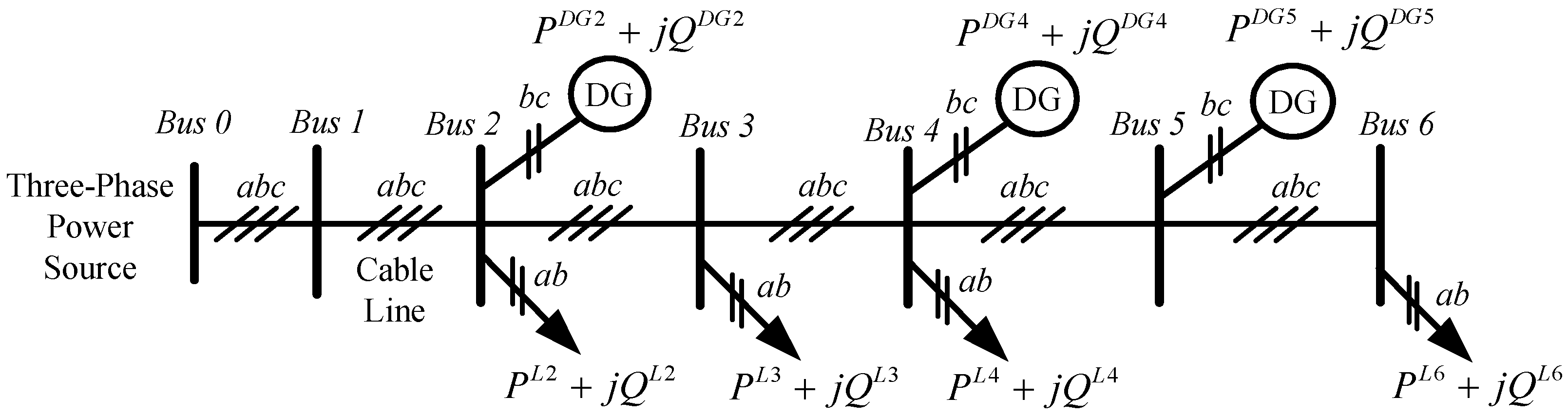
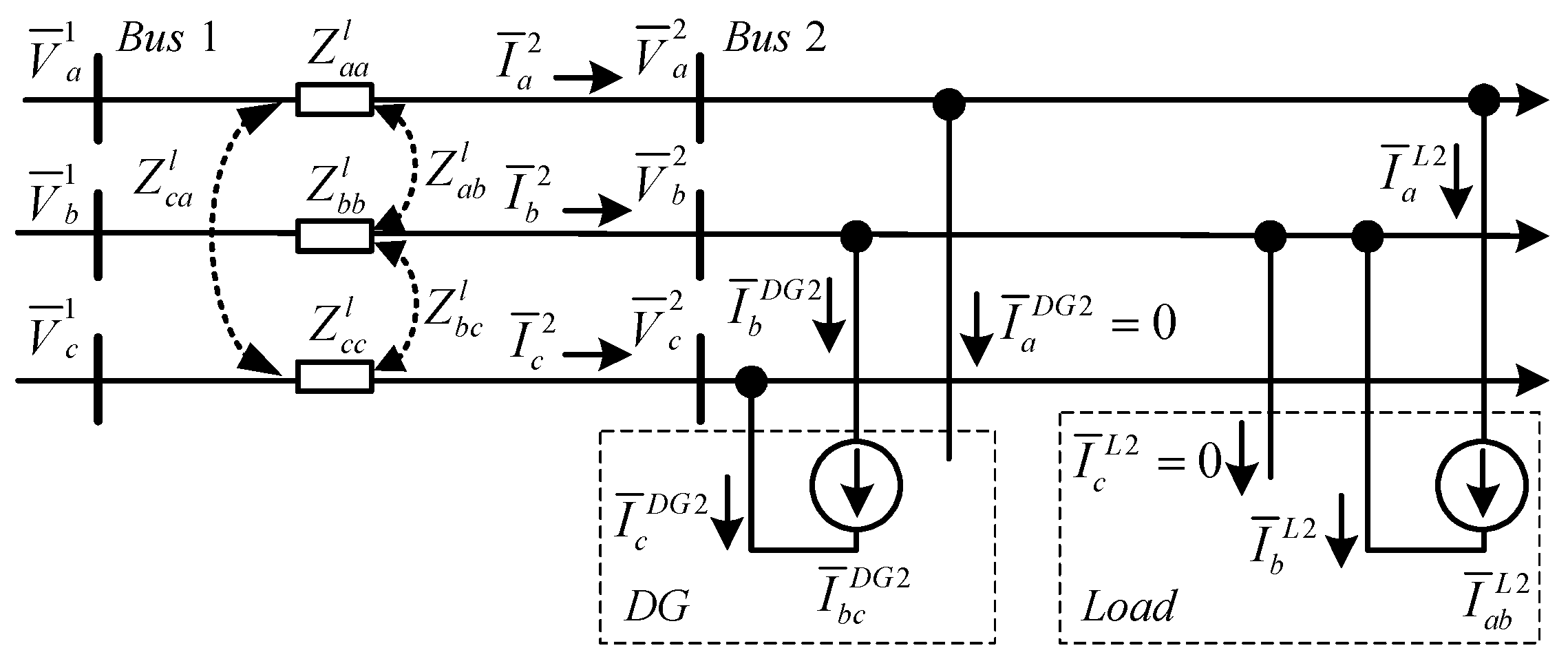
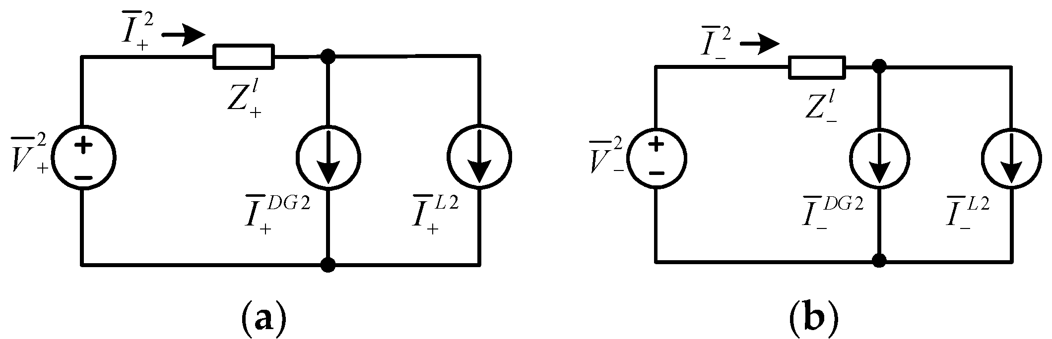
2. The Microgrid Circuit Model
Figure 1 presents a radial-type microgrid with unbalanced DGs and loads. The microgrid is a three-phase, three-wire, seven buses, radial-type microgrid with unbalanced (single-phase) DGs and loads. These single-phase DGs are connected between phase b and phase c at Bus 2, 4, 5, and single-phase loads are connected between phase a and phase b at Bus 2, 3, 4, and 6. The proposed shunt compensator can be installed on selected buses to improve the EPQ and achieve bidirectional power-flow balancing.
Figure 1.
Radial-type, three-phase microgrid with unbalanced distributed generators (DGs) and loads.
The symmetrical components method can simplify the unbalanced microgrid system for conducting a steady-state analysis. The required compensation principle of the proposed shunt compensator can also be derived. Figure 2 presents the equivalent circuit model between two neighboring buses in Figure 1. Equation (1) can be obtained by applying Kirchhoff’s Voltage Law. Equation (2) presents the impedance matrix of the three-phase distribution lines, where , , and are self-impedance and , , and are mutual impedance. In general, the mutual impedance can be neglected in a power distribution system [25]. By combining Equations (1) and (2), Equation (3) is obtained. By using the symmetrical components method, the sequence networks are derived by using Equation (4). In Equation (4), T is the symmetrical components transformation matrix and T−1 is the inverse symmetrical components transformation matrix, as presented in Equation (5).
Figure 2.
Equivalent circuit model between two buses.
A sequence circuit equation is obtained by solving Equation (4). The sequence circuit equation is presented in Equation (6), which can also be used to represent sequence networks between two neighboring buses in Figure 1.
As presented in Figure 2, the three-phase load side current comprises currents of the single-phase DG and load that are connected between phase b and phase c, and phase a and phase b, respectively. Hence, the sequence currents are expressed as a combination of the two currents, as presented in Equation (7). Figure 3 shows the sequence circuit models of Figure 2, which were used to derive the compensation principle of the compensator in Section 3.
Figure 3.
Sequence circuit models of Figure 2. (a) Positive sequence; (b) negative sequence.
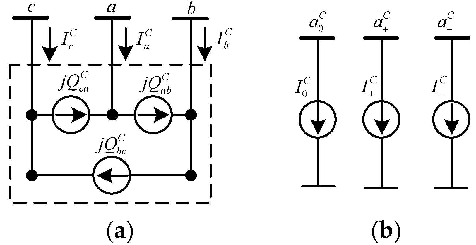
3. Compensation Principle
Figure 4 presents the main circuit structure and the corresponding sequence circuit models of the proposed compensator in the paper. Figure 4a is the three-phase, delta-connected main circuit model of the shunt compensator, which can be converted into sequence circuit models, as illustrated in Figure 4b. Figure 5 shows the system for deriving the real-time compensation scheme of the compensator. The load side current comprises the currents of the single-phase DG and load connected between different phases. The shunt compensator is used to compensate for the unbalanced load side current.
Figure 4.
Main circuit structure and corresponding sequence circuit models of the proposed compensator. (a) Main circuit structure in the a, b, c frame; (b) sequence circuit models in the 0, +, − frame.
Figure 5.
System for deriving the compensation scheme.
The three-phase line voltages of the compensator presented in Figure 5 are expressed in Equation (8). Phase a to neutral was selected as the phase angle reference. is the effective value of the line-to-neutral voltage. The three-phase line currents of the load side are expressed in Equation (9), in which the relationship of is used. By using the symmetrical components method, the positive- and negative-sequence components of the load side currents are obtained in Equations (10)–(12). The zero-sequence component is zero in a three-phase, three-wire power system.
The three arm currents and the synthesized line currents of the compensator are expressed in Equations (13) and (14), respectively. By using Equations (13) and (14), the sequence components of the synthesized compensator line currents are obtained using Equation (15). By substituting Equation (14) into Equation (15), the positive- and negative-sequence components of the compensator line currents can be rewritten as Equations (16) and (17), respectively. In Equation (15), the zero-sequence component of the line currents is zero in a delta-connected compensator.
For unbalanced-load current compensation, the compensator should eliminate the entire negative-sequence component and the imaginary part of the positive-sequence component of the load current, as shown in Equations (18) and (19) [26,27]. By combining Equations (18) and (19), the compensation command of the delta-connected compensator is obtained for each arm, as presented in Equation (20). The rating of the compensator can also be determined from Equation (20).
Figure 6 displays the positive- and negative-sequence circuits presented in Figure 1, where the proposed compensator is installed at Bus 1. Equation (21) presents the positive- and negative-sequence load side currents at each bus including the DG’s contribution. The compensator connected at Bus n can compensate for the imaginary part of the positive-sequence load side current and the entire negative-sequence load side current. For example, if the compensator is connected at Bus 1, then the compensator executes the compensation rule presented in Equations (18) and (19). Thus, the power source side only supplies a balanced three-phase current with a unity power factor, and the power quality is improved.
where, n = 2, 3, 4, 5, 6.
Figure 6.
Sequence networks of Figure 1 with the proposed compensator installed at Bus 1. (a) Positive-sequence network; (b) negative-sequence network.
4. Power Quality Indexes
Four power quality performance indexes—including voltage and current unbalance ratios, voltage regulation, and power factor—were employed for evaluating the performance of the microgrid [28,29,30].
4.1. Voltage Unbalance Ratio (VUR)
The three-phase voltage at the point of common coupling (PCC) should be maintained at a satisfactory balance condition to meet the power quality requirement. Equation (22) presents the calculation of the phase voltage unbalance ratio (PVUR).
where, .
The symmetrical components method can also be employed for evaluating the degree of unbalance. In the IEC 61000 and IEEE 1159 standard, the three-phase voltage unbalance ratio (VUR) is defined as the ratio of the negative-sequence voltage to the positive-sequence voltage, as presented in Equation (23) [31,32]. The generally used limitation value of VUR in a power distribution system is 2.5%. VUR is used in this study.
4.2. Current Unbalance Ratio (CUR)
Similarly, the CUR is presented in Equation (24) and is defined as the ratio of the negative-sequence current to the positive-sequence current.
4.3. Voltage Regulation (VR)
According to the IEEE 1547 standard, when DGs are connected to a power system, the resulting voltage fluctuation should not exceed ±5% [33]. Equation (25) presents the calculation of voltage regulation (VR), which is used to evaluate the degree of voltage fluctuation in a power system. The VR in a power distribution system should not exceed the nominal voltage by 5% at full load.
4.4. Power Factor
The power factor is the ratio of the active power to the apparent power, as presented in Equation (26), and is used to evaluate the efficiency of power utilization. Adequately correcting the power factor of a power system can improve the system operation performance.
5. Simulation Result
Figure 7 shows the study system with four single-phase DGs and loads, as presented in Figure 1. This created an extreme operating situation in the microgrid. The power quality problem and power-flow characteristics were examined at each bus. The effects of installing the compensator were also observed. Table 1 lists the system parameters of the test system. The evaluation is divided into the following four cases:
Figure 7.
Microgrid study system with unbalanced DGs and loads.
Table 1.
Test system parameters.
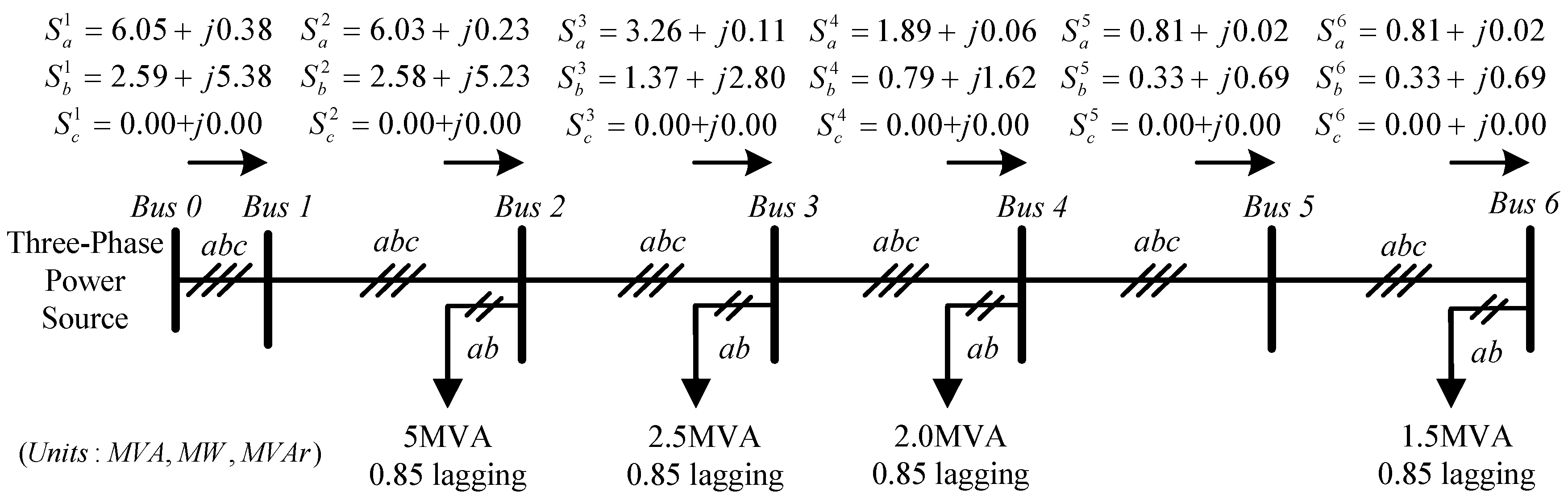
- Case 1. System with single-phase loads;
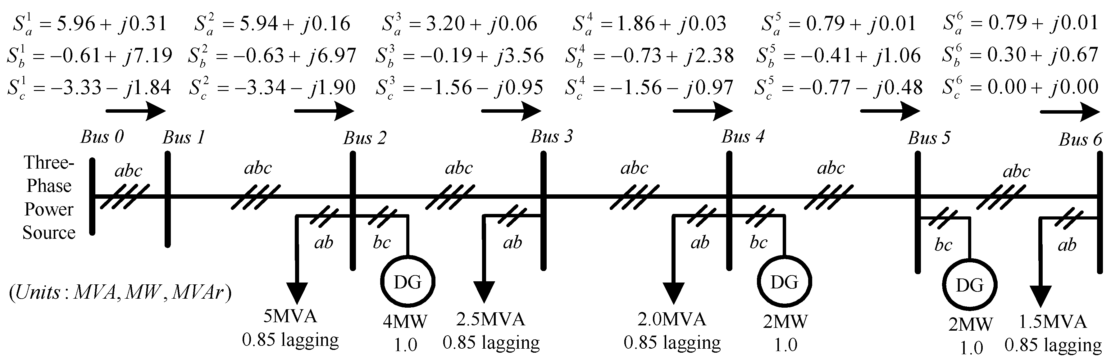
- Case 2. System with single-phase loads and DGs;
- Case 3. Case 1 system with two compensators connected at Bus 1 and Bus 4;
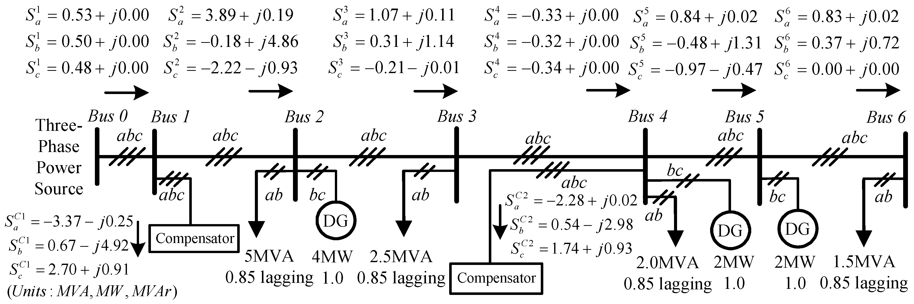
- Case 4. Case 2 system with two compensators connected at Bus 1 and Bus 4.
Four performance indexes—VUR and CUR, VR and power factor—were employed to evaluate the power quality improvement effects of the microgrid with the compensators. The MATLAB/SimuLink program was used to construct the test system presented in Figure 7 with the assigned shunt compensators. The four cases were simulated, and the results were compared in the following sections.
5.1. Case 1. System with Single-Phase Loads
In Case 1, all DGs in Figure 7 were turned-off. The power source supplies unbalanced powers to four single-phase loads. Figure 8 shows the power flow in Case 1, and Table 2 summarizes the test results. The power flow to Bus 6 is slightly lower than the assigned load demand due to the voltage drop caused by line impedance. The VR along the microgrid is within the limitation range. Equations (11) and (12) were used to calculate the sequence currents flowing to each bus. In each bus, the negative-sequence current caused by these single-phase loads is equal to the positive-sequence current, which obtains a CUR value of 100% and produces unbalanced voltage on a bus. Hence, the VURs of Bus 2 to Bus 6 are over 2.5%, which violate the generally used industrial limit value.
Figure 8.
Power flow of Case 1.
Table 2.
Test result of Case 1.
5.2. Case 2. System with Single-Phase Loads and DGs
In Case 2, all DGs were turned-on. The power source and three single-phase DGs supplied powers to four single-phase loads at the same time. Figure 9 shows the power flow in Case 2, and Table 3 summarizes the test results. The VR along the microgrid is within the limit range. In Bus 4 and 5, unbalanced active power flows to the power source side were observed. Hence, the reverse power-flow balancing is required. The power factors of Bus 1 to Bus 6 are very low. The VURs of Bus 2 to Bus 6 are higher than 2.5%, which violates the industrial limit value. When the active power of DG supplies the load demand, the net positive-sequence current is reduced. In this situation, the negative-sequence current is larger than the positive-sequence current. Thus, a CUR value higher than 100% is observed, as presented in Table 3. This also aggravates the VUR on a bus.
Figure 9.
Power flow of Case 2.
Table 3.
Test result of Case 2.
5.3. Case 3. Case 1 System with Two Compensators Connected at Bus 1 and Bus 4
Figure 10 shows the power flow in Case 3, and Table 4 summarizes the test results, respectively. Compared with Case 1, with the assistance of the compensators, the VURs of all buses were significantly improved to be within the industrial limit value. The VRs and power factors of all buses were also improved. It is observed in Figure 10 that the two compensators at Bus 1 and Bus 4 regulated the unbalanced power flows between the unbalanced load/DG and the power source side. As a result, the power source side offered balanced three-phase powers with unity power factor at Bus 1 and Bus 4.
Figure 10.
Power flow of Case 3.
Table 4.
Test result of Case 3.
5.4. Case 4. Case 2 System with Two Compensators Connected at Bus 1 and Bus 4
Figure 11 shows the power flow in Case 4, and Table 5 summarizes the test results, respectively. Compared with Case 2, the VURs of all buses were improved to be within the industrial limit value. The VRs of all buses were also compensated to satisfactory ranges. These two compensators were used in unbalanced operations for improving the power quality. The power flow in Figure 11 also indicates that reverse power balancing with a unity power factor was achieved at Bus 4 by using the compensator installed at Bus 4.
Figure 11.
Power flow of Case 4.
Table 5.
Test result of Case 4.
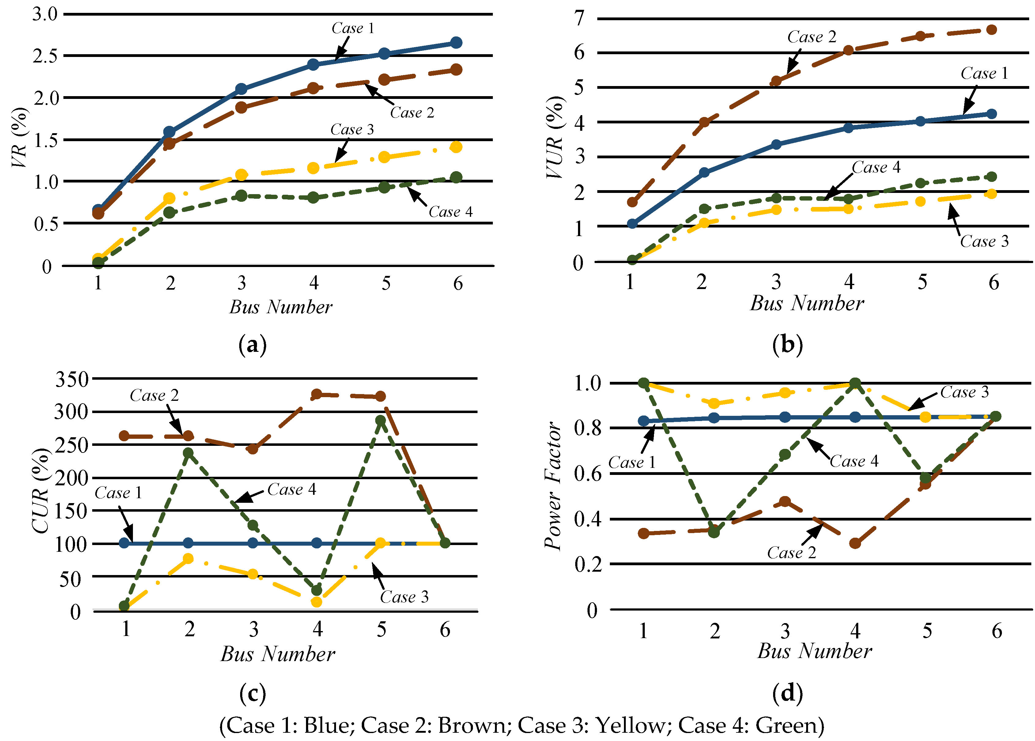
5.5. Comparison of All Cases
Table 6 presents the compensation commands of compensators in cases 3 and 4, which reveal that these two compensators were in unbalanced operations.
Table 6.
Compensation commands of compensators.
Figure 12 presents the power quality indexes of all cases. The test results revealed that the power quality was significantly improved in Cases 3 and 4, and bidirectional power-flow balancing was achieved in Case 4. Ideally, a compensator can be installed for all buses to optimize the microgrid performance.
Figure 12.
Comparison of all cases. (a) Voltage regulation; (b) voltage unbalance ratio; (c) current unbalance ratio; (d) power factor.
6. Conclusions
Improper connections of unbalanced DGs and loads in a three-phase microgrid may deteriorate system performance and increase the difficulty of operation. In this study, a shunt compensator was used in a three-phase, radial-type microgrid with unbalanced DGs and loads to achieve bidirectional power-flow balancing and improve the electrical power quality. The test results revealed that the proposed compensator provides satisfactory effects for enhancing the operational performance of a microgrid with unbalanced DGs and loads. For practical applications, the universal compensator can be implemented as SVCs, STATCOMs, or as an additional function of active filters. If necessary, an optimization method can be employed to determine the installation sites of the compensator for optimizing the operational performance of a microgrid.
Author Contributions
W.-N.C. conceived this article and designed the study system; C.-M.C. and S.-K.Y. conducted the theoretical study and software simulation; all authors wrote the paper.
Funding
This research received no external funding.
Acknowledgments
The authors would like to thank the reviewers for valuable comments.
Conflicts of Interest
The authors declare no conflict of interest.
Nomenclature
| General | |
| S | apparent power |
| P | active power |
| Q | reactive power |
| V | voltage |
| I | current |
| Z | impedance |
| R | resistance |
| X | reactance |
| Superscripts | |
| S | source |
| DG | distributed generator |
| L | load |
| l | line |
| C | compensator |
| C* | compensation command |
| n | bus number |
| * | complex conjugate |
| Subscripts | |
| 0, +, − | zero-, positive-, negative-component |
| a, b, c | phase a, b, c |
| ab, bc, ca | line a-b, b-c, c-a |
| NL | no load |
| FL | full load |
References
- Sahoo, S.K.; Sinha, A.K.; Kishore, N.K. Control techniques in AC, DC, and hybrid AC–DC microgrid: A review. IEEE J. Emerg. Sel. Top. Power Electron. 2018, 6, 738–759. [Google Scholar] [CrossRef]
- Soltani, S.H.; Rashidinejad, M.; Abdollahi, A. Dynamic phase balancing in the smart distribution networks. Int. J. Electr. Power Energy Syst. 2017, 93, 374–383. [Google Scholar] [CrossRef]
- Gallego, L.A.; Carreno, E.; Padilha-Feltrin, A. Distributed generation modelling for unbalanced three-phase power flow calculations in smart grids. In Proceedings of the 2010 IEEE/PES Transmission and Distribution Conference and Exposition, Sao Paulo, Brazil, 8–10 November 2010; pp. 323–328. [Google Scholar]
- Hashemi, S.H.; Ashouian, M.H.; Pirpiran, H.; Karami, R. Impact of distributed generation on unbalanced distribution networks. In Proceedings of the 22nd International Conference and Exhibition on Electricity Distribution (CIRED 2013), Stockholm, Sweden, 10–13 June 2013; pp. 1–4. [Google Scholar]
- Olivares, D.E.; Mehrizi-Sani, A.; Etemadi, A.H.; Cañizares, C.A.; Iravani, R.; Kazerani, M.; Hajimiragha, A.H.; Gomis-Bellmunt, O.; Saeedifard, M.; Palma-Behnke, R.; et al. Trends in microgrid control. IEEE Trans. Smart Grid 2014, 5, 1905–1919. [Google Scholar] [CrossRef]
- Khushalani, S.; Solanki, J.M.; Schulz, N.N. Development of three-phase unbalanced power flow using PV and PQ models for distributed generation and study of the impact of DG models. IEEE Trans. Power Syst. 2007, 22, 1019–1025. [Google Scholar] [CrossRef]
- Fu, Q.; Montoya, L.F.; Solanki, A.; Nasiri, A.; Bhavaraju, V.; Abdallah, T.; Yu, D.C. Microgrid generation capacity design with renewables and energy storage addressing power quality and surety. IEEE Trans. Smart Grid 2012, 3, 2019–2027. [Google Scholar] [CrossRef]
- Eftekharnejad, S.; Vittal, V.; Heydt, G.T.; Keel, B.; Loehr, J. Impact of increased penetration of photovoltaic generation on power systems. IEEE Trans. Power Syst. 2013, 28, 893–901. [Google Scholar] [CrossRef]
- Tavakoli, M.; Shokridehaki, F.; Marzband, M.; Godina, R.; Pouresmaeil, E. A two stage hierarchical control approach for the optimal energy management in commercial building microgrids based on local wind power and PEVs. Int. J. Sustain. Cities Soc. 2018, 41, 332–340. [Google Scholar] [CrossRef]
- Tavakoli, M.; Shokridehaki, F.; Akorede, M.F.; Marzband, M.; Vechiu, I.; Pouresmaeil, E. CVaR-based energy management scheme for optimal resilience and operational cost in commercial building microgrids. Int. J. Electr. Power Energy Syst. 2018, 100, 1–9. [Google Scholar] [CrossRef]
- Marzband, M.; Fouladfar, M.H.; Akorede, M.F.; Lightbody, G.; Pouresmaeil, E. Framework for smart transactive energy in home-microgrids considering coalition formation and demand side management. Int. J. Sustain. Cities Soc. 2018, 40, 136–154. [Google Scholar] [CrossRef]
- Marzband, M.; Azarinejadian, F.; Savaghebi, M.; Pouresmaeil, E.; Guerrero, J.M.; Lightbody, G. Smart transactive energy framework in grid-connected multiple home microgrids under independent and coalition operations. Int. J. Renew. Energy 2018, 126, 95–106. [Google Scholar] [CrossRef]
- Hong, T.; de León, F. Controlling non-synchronous microgrids for load balancing of radial distribution systems. IEEE Trans. Smart Grid 2017, 8, 2608–2616. [Google Scholar] [CrossRef]
- Sgouras, K.I.; Bouhouras, A.S.; Gkaidatzis, P.A.; Doukas, D.I.; Labridis, D.P. Impact of reverse power flow on the optimal distributed generation placement problem. IET Gener. Transm. Distrib. 2017, 11, 4626–4632. [Google Scholar] [CrossRef]
- Roy, N.K.; Pota, H.R. Current status and issues of concern for the integration of distributed generation into electricity networks. IEEE Syst. J. 2015, 9, 933–944. [Google Scholar] [CrossRef]
- Wandhare, R.G.; Agarwal, V. Reactive power capacity enhancement of a PV-grid system to increase PV penetration level in smart grid scenario. IEEE Trans. Smart Grid 2014, 5, 1845–1854. [Google Scholar] [CrossRef]
- Safayet, A.; Fajri, P.; Husain, I. Reactive power management for overvoltage prevention at high PV penetration in a low-voltage distribution system. IEEE Trans. Ind. Appl. 2017, 53, 5786–5794. [Google Scholar] [CrossRef]
- Camilo, F.M.; Castro, R.; Almeida, M.E.; Fernão Pires, V. Assessment of overvoltage mitigation techniques in low-voltage distribution networks with high penetration of photovoltaic microgeneration. IET Renew. Power Gener. 2018, 12, 649–656. [Google Scholar] [CrossRef]
- Massignan, J.A.D.; Pereira, B.R.; London, J.B.A. Load flow calculation with voltage regulators bidirectional mode and distributed generation. IEEE Trans. Power Syst. 2017, 32, 1576–1577. [Google Scholar]
- Elrayyah, A.Y.; Wanik, M.Z.C.; Bouselham, A. Simplified approach to analyze voltage rise in LV systems with PV installations using equivalent power systems diagrams. IEEE Trans. Power Deliv. 2017, 32, 2140–2149. [Google Scholar] [CrossRef]
- Ghosh, A.; Ledwich, G. Power Quality Enhancement Using Custom Power Devices; Kluwer Academic Publishers: Dordrecht, The Netherlands, 2002. [Google Scholar]
- Chang, W.N.; Liao, C.H. Design and implementation of a STATCOM based on a multilevel FHB converter with delta-connected configuration for unbalanced load compensation. Energies 2017, 10, 921. [Google Scholar] [CrossRef]
- Miller, T.J.E. Reactive Power Control. In Electric System; Wiley & Sons: Hoboken, NJ, USA, 1982. [Google Scholar]
- Quintela, F.R.; Arévalo, J.M.G.; Redondo, R.C. Power analysis of static VAr compensators. Int. J. Electr. Power Energy Syst. 2008, 30, 376–382. [Google Scholar] [CrossRef]
- Yang, N.C.; Chen, H.C. Decomposed Newton algorithm-based three-phase power-flow for unbalanced radial distribution networks with distributed energy resources and electric vehicle demands. Int. J. Electr. Power Energy Syst. 2018, 96, 473–483. [Google Scholar] [CrossRef]
- Lee, S.Y.; Wu, C.J.; Chang, W.N. A compact algorithm for three-phase three-wire system reactive power compensation and load balancing. Electr. Power Syst. Res. 2001, 58, 63–70. [Google Scholar] [CrossRef]
- Chang, W.N.; Chang, C.M.; Yen, S.K. Developing universal compensator in a microgrid with distributed generations to improve operation performance. In Proceedings of the 2018 IEEE International Conference on Applied System Invention (ICASI), Chiba, Japan, 13–17 April 2018; pp. 212–215. [Google Scholar]
- Bergen, A.R.; Vittal, V. Power Systems Analysis, 2nd ed.; Prentice Hall: Upper Saddle River, NJ, USA, 2000. [Google Scholar]
- Saadat, H. Power System Analysis, 3rd ed.; PSA Publishing LLC: London, UK, 2011. [Google Scholar]
- Anward, M.; Hiendro, A. New unbalance factor for estimating performance of a three-phase induction motor with under- and overvoltage unbalance. IEEE Trans. Energy Convers. 2010, 25, 619–625. [Google Scholar] [CrossRef]
- International Electrotechnical Commission. Power Quality Standard; IEC 61000; International Electrotechnical Commission: Geneva, Switzerland, 2015. [Google Scholar]
- Institute of Electrical and Electronics Engineers. IEEE Recommended Practice for Monitoring Electric Power Quality; IEEE 1159; Institute of Electrical and Electronics Engineers: Piscataway, NJ, USA, 2009. [Google Scholar]
- Institute of Electrical and Electronics Engineers. IEEE Standard for Interconnection and Interoperability of Distributed Energy Resources with Associated Electric Power Systems Interfaces; IEEE 1547; Institute of Electrical and Electronics Engineers: Piscataway, NJ, USA, 2018. [Google Scholar]
© 2018 by the authors. Licensee MDPI, Basel, Switzerland. This article is an open access article distributed under the terms and conditions of the Creative Commons Attribution (CC BY) license (http://creativecommons.org/licenses/by/4.0/).