1. Introduction
Research in the field of intentional islanding operation of distribution systems has been increased day by day due to economic and technical reasons [
1,
2]. Intentional islanding operation of power systems presents numerous advantages, such as improved reliability of the network, improved voltage and frequency profile, as well as decreased transmission losses [
3].
Islanding is a generic term which describes the condition where a section of a power network supplied by Distributed Generation (DG) units is separated from the main grid. This separation of the grid may be due to the operation of protection devices responding in case of faulted condition. The current trend in design and operation of the networks does not allow the operation of these islands for safety and security reasons. Islanding in turn can be used to improve reliability of the power networks in case of significant penetration of DG units if the islanding-related problems are tackled properly. Serious issues with islanding are the voltage and the frequency deviations, island detection (ID), load control, and protection [
4,
5].
With significant penetration of DG units, islanding operation of a local Micro Grid (MG) can be a viable solution if the voltage and frequency of the islanded portion of the power network is controlled locally. If there is imbalance between active power load demand and active power generation during islanding, the frequency of the islanded MG deviates from its nominal values. If the active power generation is less than the active power load demand in the islanded portion of the network, the network frequency decreases and vice versa. If there is excess availability of the reactive power in the islanding, the MG voltage increases and vice versa.
The new trend in modern power networks is to ensure the controllability of islanded MGs. The controllability of MG may be obtained if the desired amount of active and reactive power support is provided in the local MG. This can be achieved if an appropriate control system is developed.
The development of the control system for DG units in the islanded mode is different from that of the grid connected mode. The control system in the grid connected mode might be developed either in Power-Voltage (PV) or Active-Reactive Power (PQ) modes and the subject to be controlled depends on the situation. If a goal is to control voltage and the active power of the respective DG units, the control system should be developed in PV mode. If the target is to control the reactive power of the units in order maximize its active power delivery, the control system should be developed in PQ mode.
When the distribution system is disconnected from the main transmission grid, it loses its slack reference, since the main transmission grid acts as a slack bus in the grid connected mode. This slack reference is established in the islanded mode if one of the control systems for one of the DG units is developed as a Voltage-Frequency (VF) controller [
6].
The VF controller should be chosen for the DG unit which has a significant amount of energy available (i.e., batteries) and a fast response (i.e., 0.02 s in this case). A DG unit having a certain amount of power can be assigned a VF controller. Since batteries have a feature to provide constant power, they can be a good choice for assigning the VF controller. The DG units such as PVs, WTGs, etc., have unpredictable power capabilities and are not considered for the VF controller. In the case of several parallel connected inverters in the islanded MG, one of the inverter controllers must be developed in VF mode and the others either in PV or PQ modes [
6,
7].
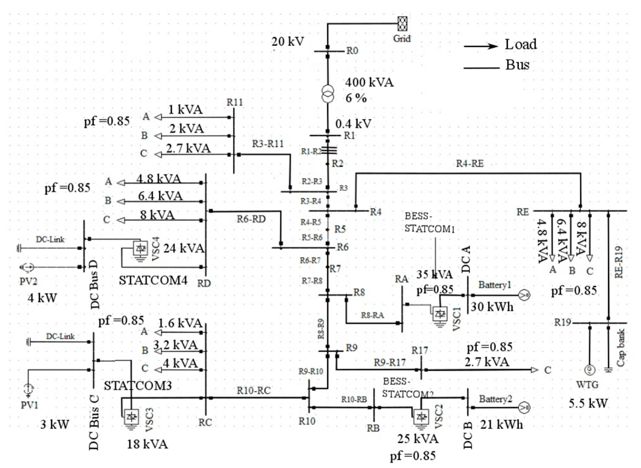
A test distribution network set up by The International Council on Large Electric Systems (CIGRE) comprising Wind Turbine Generator (WTG), PV solar generation units, and energy storage devices at different locations has been chosen for this study. The single line diagram of this distribution system modeled in DIgSILENT power factory software 15.0 is shown in
Figure 1.
There are two PV solar generation units of 3 kW and 4 kW which are connected at bus RC and RD respectively. This network also comprises of one fixed-pitch, fixed-speed wind turbine generator of 5.5 kW which is connected at bus R19. There are two batteries connected at bus RA and at bus RB. The size of inverters for batteries connected at RA and RB is 35 kVA and 25 kVA, respectively. The STATCOM is used for each PV and battery units. The STATCOM for PV units is generally named PV-STATCOM and the STATCOM for battery units is named BESS-STATCOM. The size of STATCOM for PV units is assumed to be six times higher than the size of the PV units rating which is mentioned in
Figure 1. The oversizing of PV inverters is done in order to regulate the voltage variations during nighttime when there are lot of wind and load variations [
9,
10,
11]. During nighttime, the feeder loads are much lower as compared to daytime, whereas wind farms produce more power due to increased wind speed. This causes the reverse flow of power from the point of connection to the main grid with the rise in the feeder voltage above the tolerable limits.
The size of BESS-STATCOMs is assumed to be the size of the battery inverters which is given in the single line diagram of the CIGRE network shown in
Figure 1. Lithium-ion (Li-ion) batteries are considered in this research study. The specifications of a single cell of a Li-ion battery are presented in
Appendix A [
12].
All DG units in the CIGRE network are three-phase symmetrical sources; if one-phase DG units are considered, it will cause power unbalancing problems in there. These symmetric DG units are integrated into the grid by using a 0.4 MVA, 20 kV/0.4 kV Dyn1 transformer, grounded with, Z = 0.0032 + j0.0128 ohms. The detailed information related to the different cables/lines used in the network is presented in
Appendix B [
7].
Several researchers have done lot of work in the area of islanding. Islanding, its control techniques, and the controllability of MG by using a load shedding technique are presented in [
13]. Control of the voltage and frequency in islanding by employing droop controller is given in [
13,
14,
15]. A very good concept is presented in [
15]; however, work is still needed in case of several parallel connected inverters. The secondary control scheme for unbalanced mitigation in droop controlled-based islanding MGs is described in [
16,
17]. Further work in the same area is done by using different techniques and is found in [
18,
19]. Furthermore, the stability of the frequency control in the islanded portion of the CIGRE low voltage distribution is described in [
20]. The authors have described the matter in detail concerning the frequency control, but the stability of voltage in the islanded portion of the micro grid is not dealt with in this paper. The study of a novel approach to control the frequency and the voltage of micro grids in islanding operation is described in [
21]. The authors have taken the IEEE modified 13-bus standard network in which DG units are installed in combination with wind and fuel cell integration. In addition, the authors have proposed a control strategy using droop characteristic in order to control the frequency and the voltage of the islanded MG. The use of STATCOM controllers and assigning VF controllers to any specific DG units among the units available in islanded MG is not included in this paper.
The novelty of this paper is that it describes the clear concepts of establishing a VF controller in the islanded portion of the CIGRE low voltage distribution network and presents a clear idea how to assign VF controller and to which of the existing DG units in the network. The advanced power electronics devices such as STATCOMs (i.e., for PV units) and BESS-STATCOMs (i.e., for batteries) employing Proportional Integral (PI) controllers are used to ensure the controlled operation of the islanded MG in this paper. The major contributions of the paper are mentioned below:
- ➢
The establishment of VF controller in the islanded portion of CIGRE low voltage distribution network in case DG units are integrated into the islanded MG.
- ➢
Assigning VF controller to the most suitable DG Units available in MG among all the available DG units.
- ➢
The control of voltage and frequency in the islanded portion of the MG.
This paper is organized as follows:
Section 2 describes the control strategy which is able to compensate the voltage problems in islanded mode. The selection of VF controller for the most suitable DG unit of the CIGRE network and other similar networks is also presented in this section.
Section 3 presents the simulation results in order to verify that the developed controllers are working correctly in islanded mode. Finally, conclusions are presented in
Section 4.
2. Control Strategy for the Islanding Operation of the CIGRE Network and Selection of the Voltage-Frequency Controller for the Most Suitable Distributed Generation Units
In the grid connected mode, STATCOM controllers for PVs have been developed in such a way that they control oscillations in the DC link and AC voltages by providing the desired amount of active power, and reactive powers and are described in detail in [
22]. The control system for the PV units is developed in PV mode by using the STATCOM principle. The controllers for the Battery Energy Storage Systems (BESS) can be developed either in PQ or PV mode utilizing STATCOM concepts (i.e., BESS-STATCOMs), depending on what parameter needs to be controlled. In [
22], the controllers for BESS applications are developed in PQ mode. These controllers control the flow of active-reactive power and also charge/discharge the batteries at different charging rates [
22].
Since different DG units in the CIGRE low voltage network are connected in parallel, the VF controller will be assigned to only one of the DG units in the network in case of islanding. As the power output of PV and WTG is uncertain depending on the weather conditions, these units in the CIGRE network cannot be assigned with the VF controller. The BESS are then the only remaining DG units in this network. Since BESS-based DG units can have a significant amount of energy available and a fast response, it might be a good choice to develop a VF controller for one of the BESS units. As BESS1, which connected at bus RA in the CIGRE network, has a bigger energy capacity (i.e., 30 kWh) than BESS2 (i.e., 21 kWh) at bus RB; VF controller in this case is developed for BESS1. Hence, the proposed strategy of VF controller utilizes inverter or battery-based DG units. The classical asynchronous generators used in hydro power plants are not considered in this case.
It can be said that the control systems for both PV units and BESS2 in case of islanding remains the same as that in the grid connected mode, and only the control system of BESS1 switches from PQ/PV mode to VF mode. The controllers for PV units and BESS1 in the grid connected mode are described in [
7,
22]; therefore, further details of these controllers are not presented in this paper. Instead, the control system of BESS1 in the grid and islanding mode are described here.
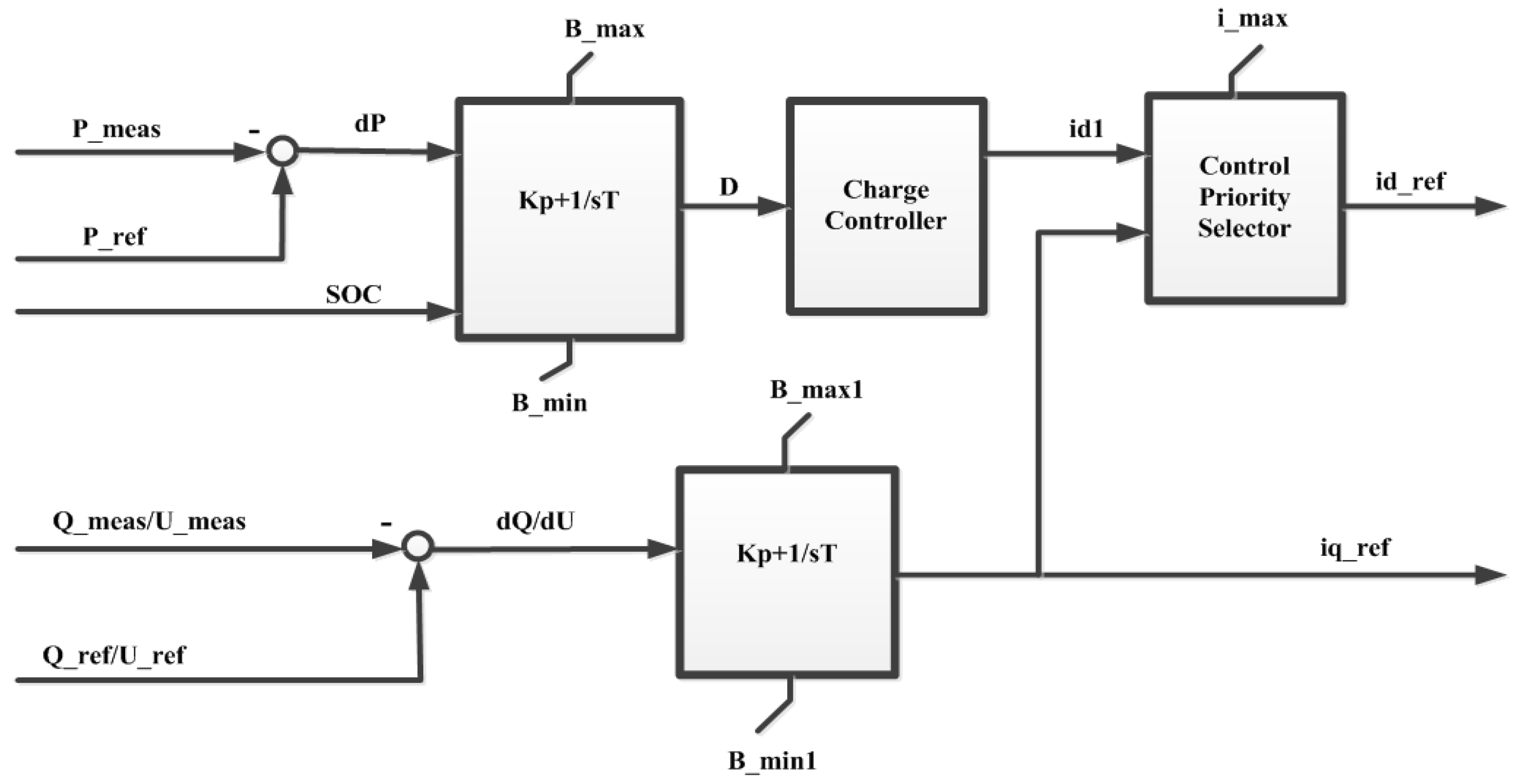
Figure 2 and
Figure 3 show the control system of BESS1 in the grid connected and islanding modes, respectively.
The control system for the grid connected mode as shown in
Figure 2 works in such a way that it compares the measured and reference values of active and reactive power (or the voltage if it is required to control the voltage at the point of the connection) and sends the respective error signal to respective PI controllers in order to produce the current references (i.e., id_ref and iq_ref). The author has presented further detailed explanations about the working and the operation of this controller in his published work [
7,
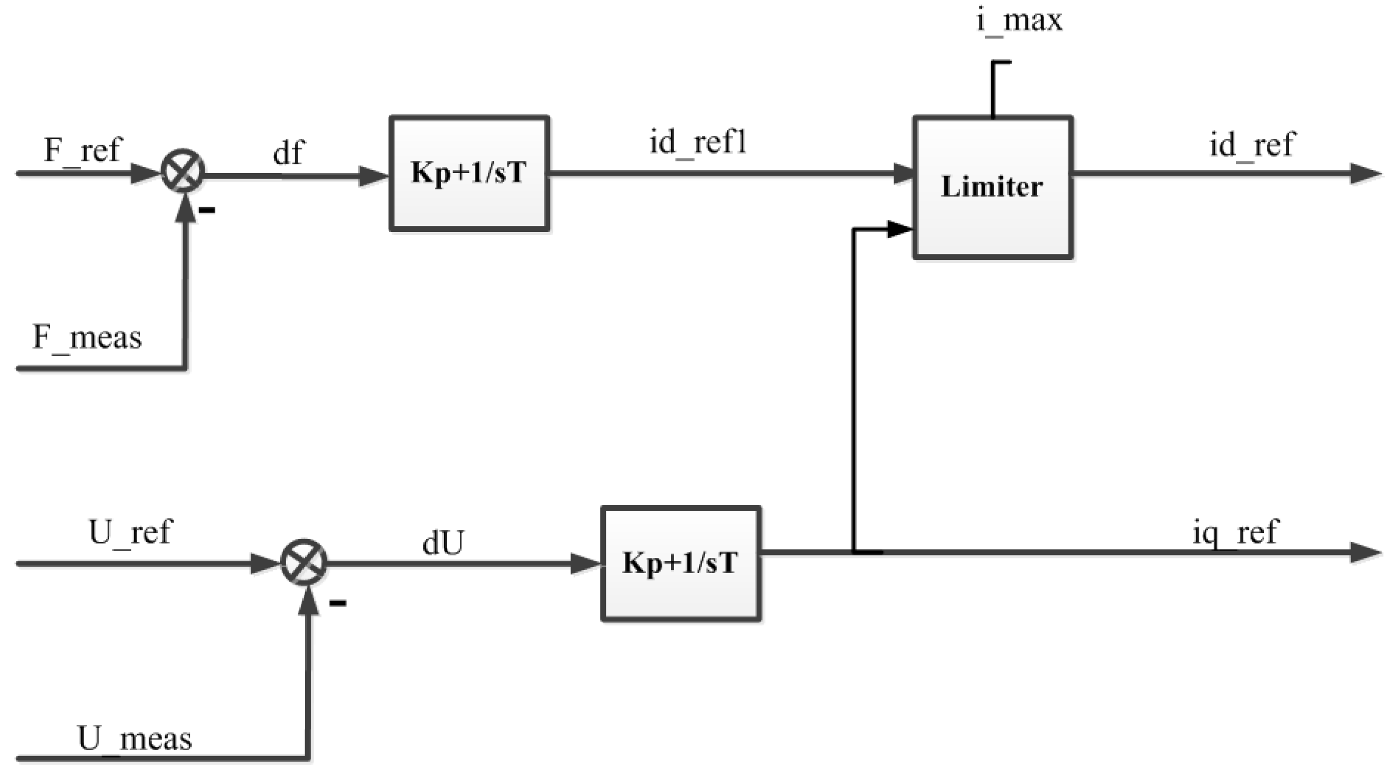
22]. The purpose of VF controller as shown in
Figure 3 is to control the frequency of the MG by injecting or absorbing the desired amount of the active power. It is also used to control the voltage of MG by injecting or absorbing the desired amount of the reactive power. This controller compares measured and reference frequency (i.e., F_ref = 50 Hz) and sends the error signal ‘df’ to the PI controller which generates active current reference (id_ref) as shown in
Figure 3. It also compares measured and reference voltages at a certain bus and sends error signal ‘dU’ to the PI controller responsible for the voltage control loop. This PI controller generates the reactive current reference (iq_ref) and adjusts the injection or the absorption of the reactive power. Tuning of PI controllers for the different controllers used in the network is done by using a trial and error method. The different values have been tried in order to tune the controller in a proper manner and an overshoot between the measured and reference values of the current has been observed. The suitable values have been chosen for the control parameters where no major issues of the overshoot exist in the measured and the reference values of the signal.
Table 1 shows the tuning parameters of VF controller. The time constant selected for this controller is based on the fact that the inner current controller is set as the faster controller as compared to the outer controller.
The active and reactive power sharing (i.e., injection/absorption) by the inverters is according to the values of the current references. These references are the input to the current controller which is responsible to set the duty cycle for the switches used in the inverter. The share of
P and
Q from the VF controller is according to Equations (1) and (2) and depends on whether the controller has been given the priority of the voltage of the frequency control:
where
i_max lies between ±1 p.u. The control system generating signal id_ref according to Equation (1) is said to have the voltage control priority. If the inverter delivers 1 p.u of the reactive power; then, according to Equation (1), the inverter has no more active power to inject (i.e., id_ref = 0). The controllers of the other inverters used in the CIGRE network have also been modeled to share the amount of the active and the reactive power according to Equation (1). The switching of the controller from PQ/PV mode to VF mode as shown in
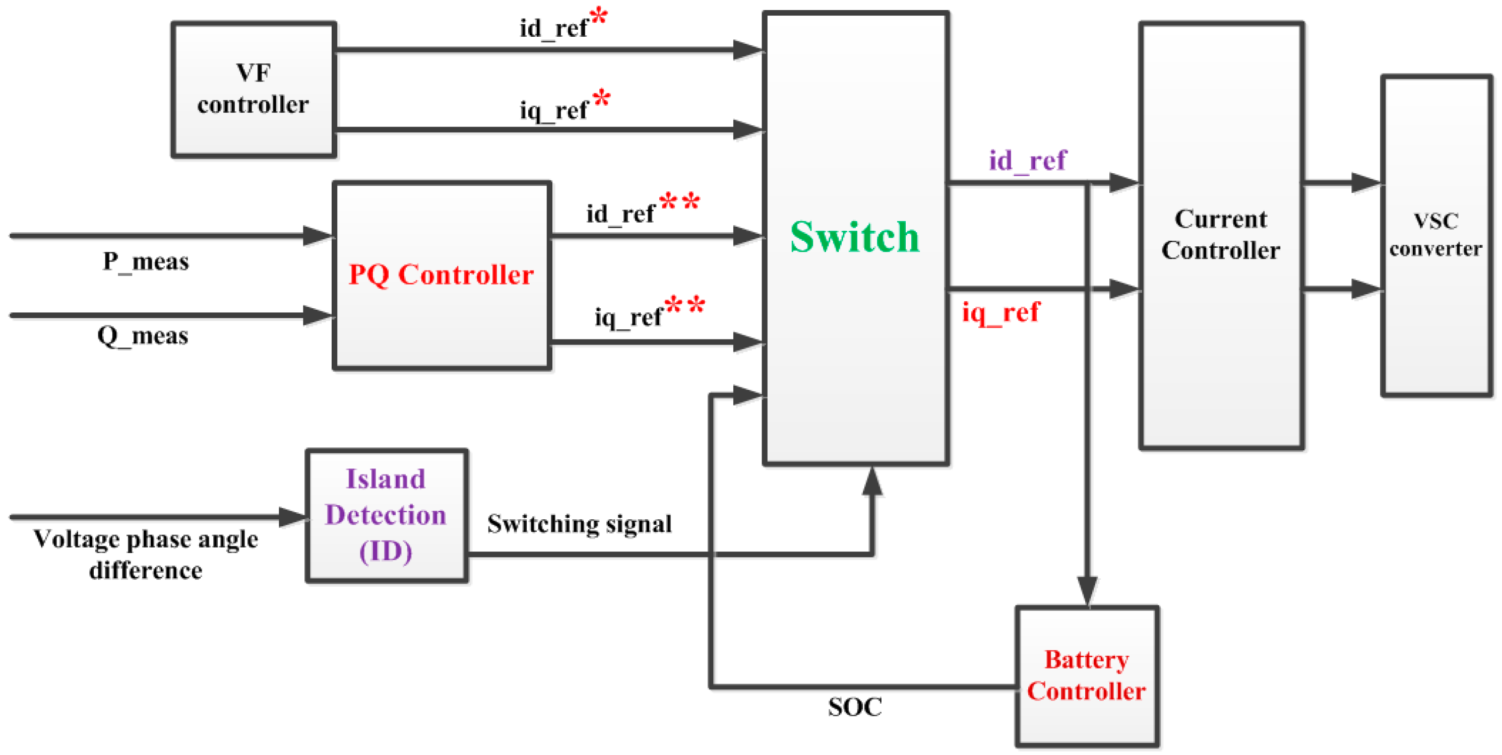
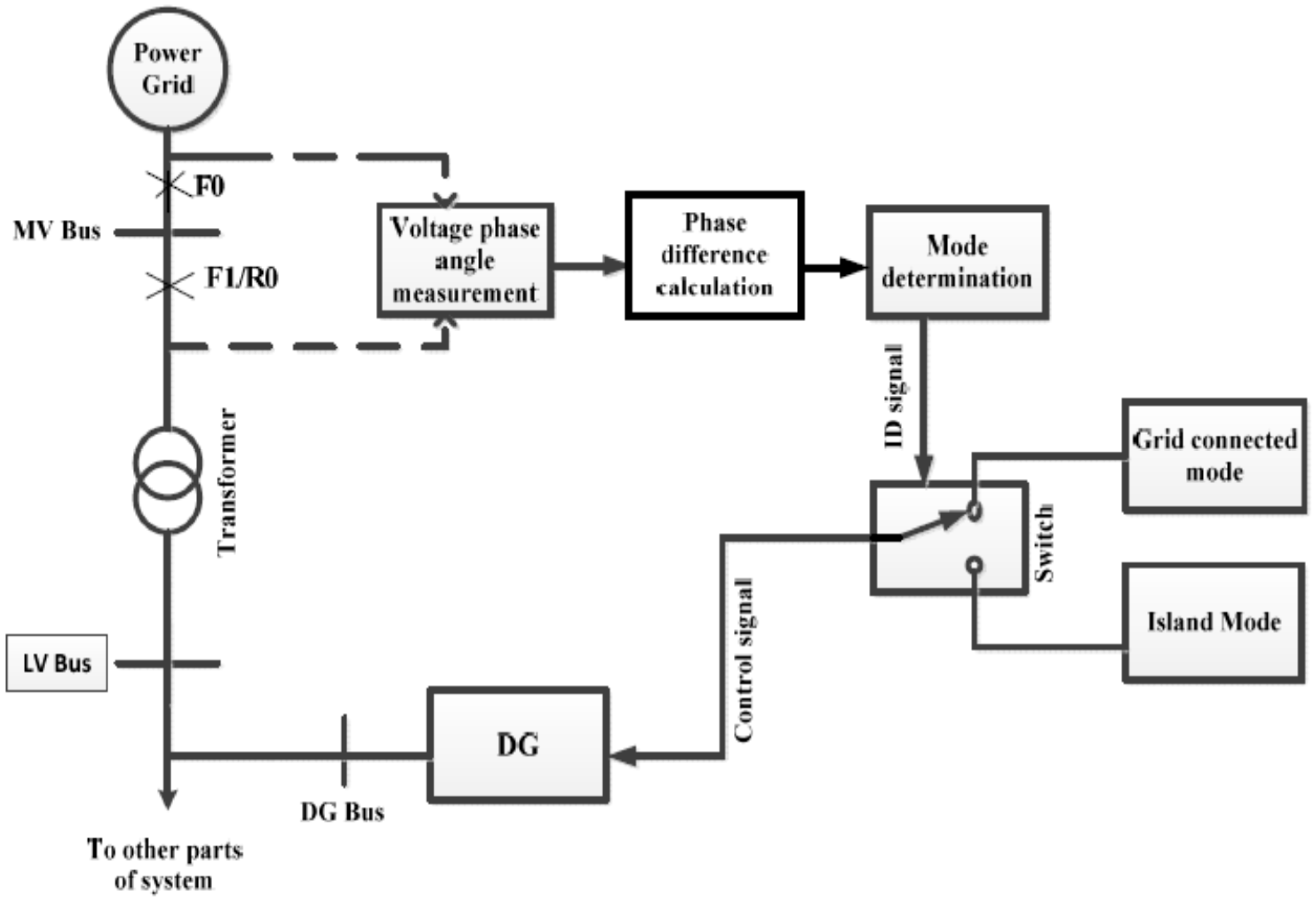
Figure 4 is made according to islanding detection. Islanding in this case is detected by using a phase angle difference measurement method and is shown in
Figure 5.
It can be seen in
Figure 4 that two different controllers (i.e., PQ and VF controllers) are used for the two different conditions (i.e., grid connected and island) of the network. The PQ controller shown in
Figure 2 produces current reference signals (id_ref** and iq_ref**). VF controller shown in
Figure 3 generates the output signals (i.e., id_ref* and iq_ref*). The transition of the control system from the PQ mode to VF mode is made by the ID block. The working of the ID block is shown in
Figure 5. It can be seen in
Figure 5 that the difference of the voltage phase angles between the transmission and the distribution grid is measured. Islanding is detected if any difference in the voltage phase angles of the two grid sides exists. Further details on this method, its validation, and comparison with the other methods are presented in [
5,
24].
The switch block shown in
Figure 4 receiving the signals (id_ref** and iq_ref**) and (id_ref* and iq_ref*) from the PQ controller and VF controller, respectively, at its input, sends appropriate current references to the current controller according to the ID signal. If the ID signal is 1 (i.e., islanding detected), the current controller receives the active and the reactive current references from VF controller, and if the ID signal is 0 (i.e., no islanding), the current controller receives signals from the PQ controller. The current controller which receives the signals from the PQ or VF controllers sends the signals to the PWM block of the inverter and decides the duty cycle [
25]. The details of the current controller are described in [
7].
3. Simulation Results
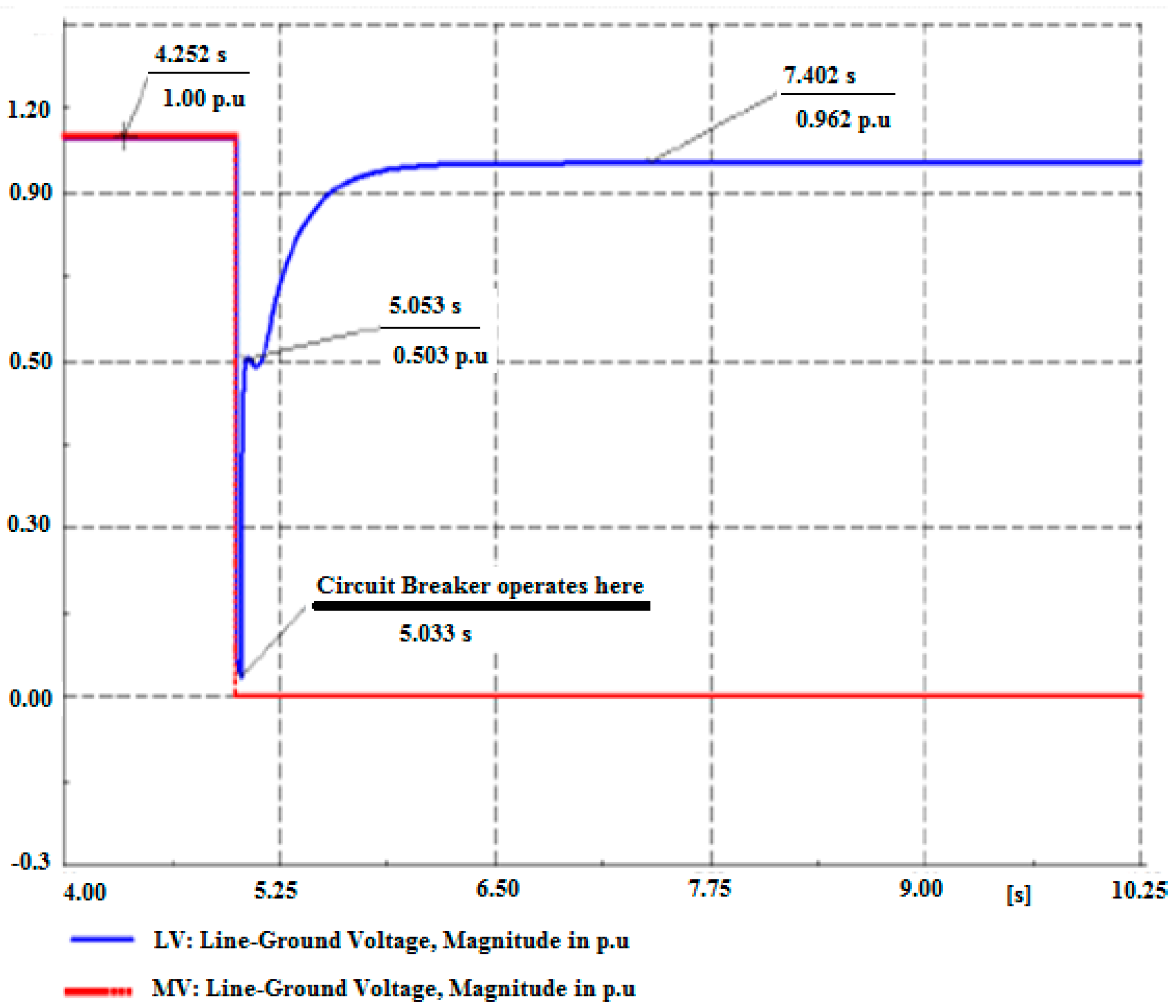
In order to study the effectiveness of the developed controllers in islanding, the voltage profile of bus R0 (i.e., Medium Voltage (MV) bus) and bus R1 (i.e., LV bus) of the CIGRE low voltage distribution network is shown in
Figure 6. Under normal operating conditions, the voltage on both of these buses is at 1 p.u. At time
t = 5 s, a three-phase fault is applied at the MV bus and the voltage on bus R0 and R1 decreases as shown in
Figure 6.
The procedure of clearing such a fault at this point (i.e., MV bus) is described in [
17]. When such a fault is cleared from both sides (i.e., from the primary and the secondary sides of the transformer used in the CIGRE network), the distribution network enters into islanding condition. It can be seen in
Figure 6 that when the circuit breaker operated by relay R0 has cleared the fault at
t = 5.033 s; the existing controllers (i.e., four STATCOM controllers) in the local MG quickly restore the voltage back to acceptable limits (i.e., ±10% according to the IEEE standard 1159–1995 and Danish standards [
17,
26]). The restoration of the voltage in the local MG is made by providing the required amount of reactive power by the inverter-based DG units.
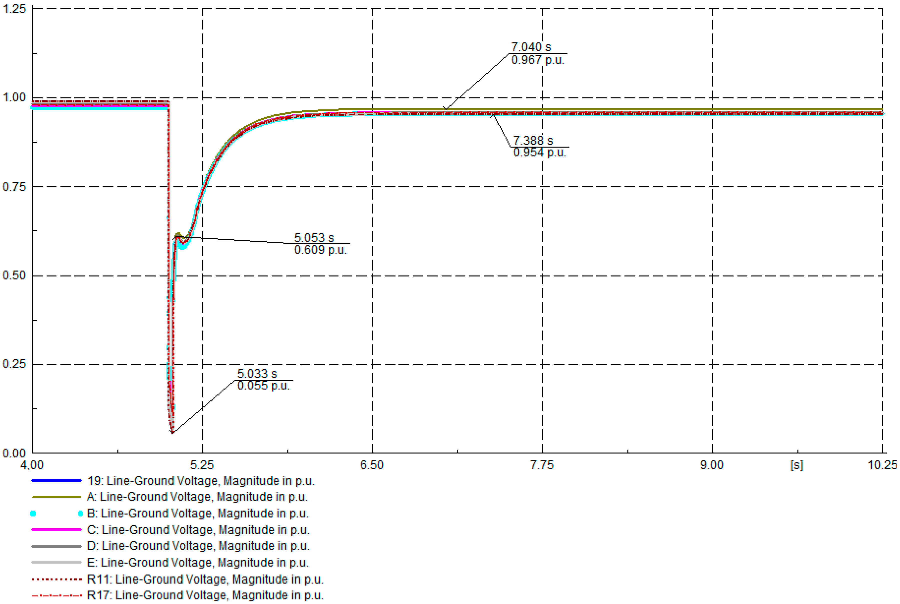
The voltage seen on the other parts of the CIGRE network also decreases when the distribution system is disconnected from the main transmission grid. To see the voltage profile on the different branches of islanded MG, the voltage on bus R19, RA, RB, RC, RD, RE, and bus R11 is shown in
Figure 7. The results presented in
Figure 7 are conducted when BESS1 is considered to be 50% charged. Much improved response of the voltage can be obtained if BESS1 is considered to be 95% charged and is because of no flow of the current towards BESS1 in order to charge. This reduces the line losses across bus RA where BESS1 is connected which in turn gives better voltage response while compensating.
There is a minor imbalance between the voltages in the normal operating conditions as shown in
Figure 7. This imbalance in the voltage is due to the presence of DG units, BESS units, and unbalanced loads connected at different nodes of the network. At the time of islanding the voltage in all parts of the network decreases as shown in
Figure 7 and is due to the loss of slack bus. The voltages shown in the different parts of the CIGRE network are restored to the acceptable limits by providing/absorbing the desired/extra amount of the reactive power. The injection or absorption of the reactive power is decided by the corresponding controllers and the decision is made according to the value of the voltage seen by the inverters at their points of the connection and if the controllers are given the voltage control priority [
7].
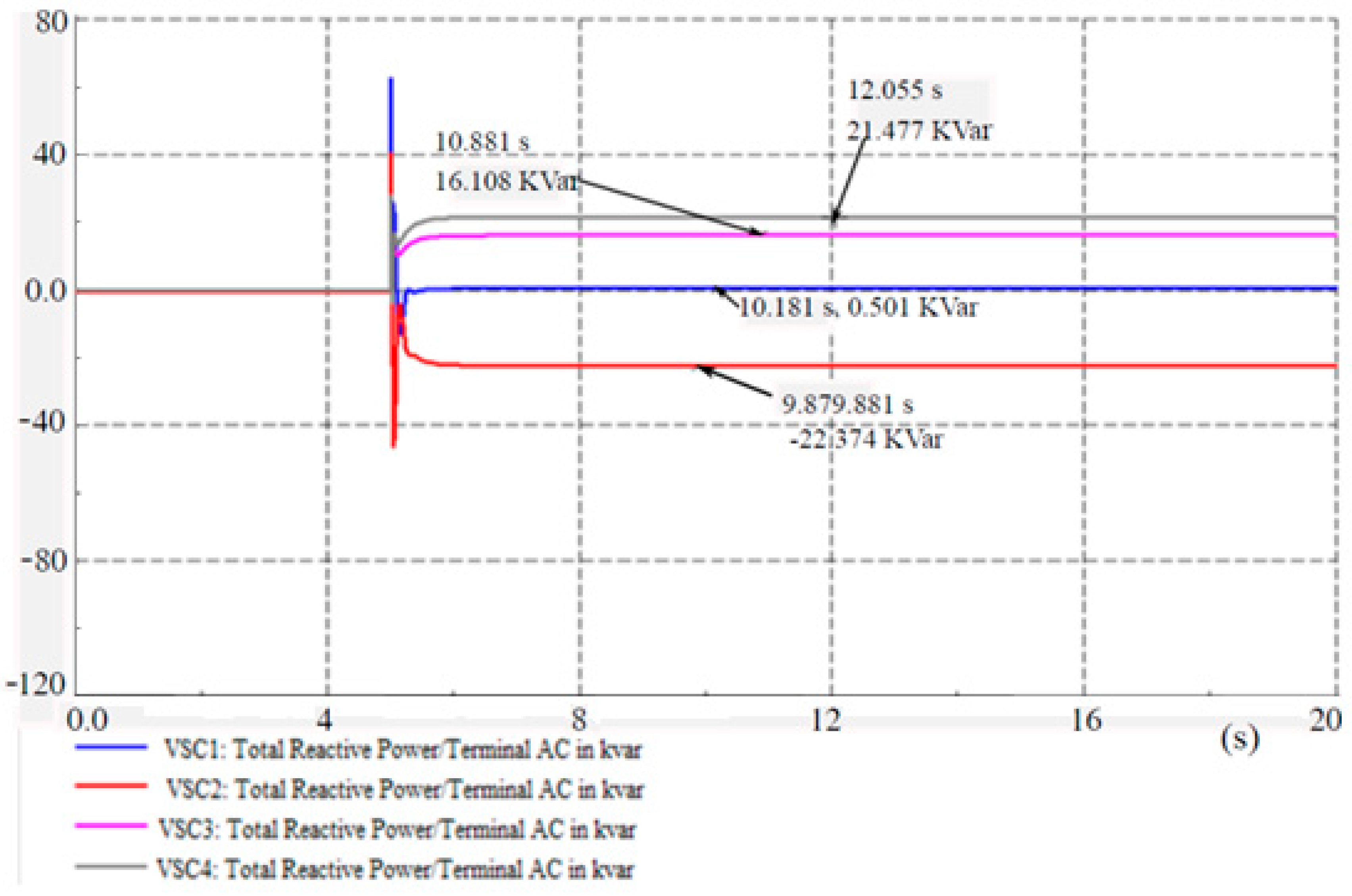
The inverters of battery-based DG units are named VSC1 (i.e., BESS1) and VSC2 (i.e., BESS2) whereas the inverters of PV units are named VSC3 (i.e., PV1) and VSC4 (i.e., PV2). The reactive power injected by the inverters of the existing DG units of the CIGRE network is shown in
Figure 8.
It can be seen in
Figure 8 that all inverters do not inject reactive power in the normal operating conditions. VSC3 and VSC4 inject 16.108 kvar and 21.477 kvar of reactive power, respectively, at the time when the distribution system is islanded. VSC2 absorbs 22.374 kvar in the island condition as shown in
Figure 8, whereas VSC1 injects only 0.501 kvar in island mode because it has been assigned the priority to inject the maximum amount of the active power in order to maintain the network frequency [
7]. Hence, the developed controllers have ensured the constancy of the voltage in the islanded MG.
The frequency of the islanded MG is controlled by providing the active power by the existing inverter-based DG units available in the local MG. The different loads are connected at the different buses in the CIGRE network. Both the batteries charge in the normal operating conditions if they are not fully charged; hence, they act as loads in the grid connected modes.
Table 2 shows the power produced by the power grid and DG units in the normal operating conditions. It also displays the active power consumed by the loads.
When the distribution system enters into islanding, it loses 84.45 kW of power. The lost power must be delivered by the existing DG units available in the local MG in order to maintain the constancy of the frequency there.
Table 3 depicts the power delivered by the DG units and the active power consumed by the loads in the local MG during island conditions.
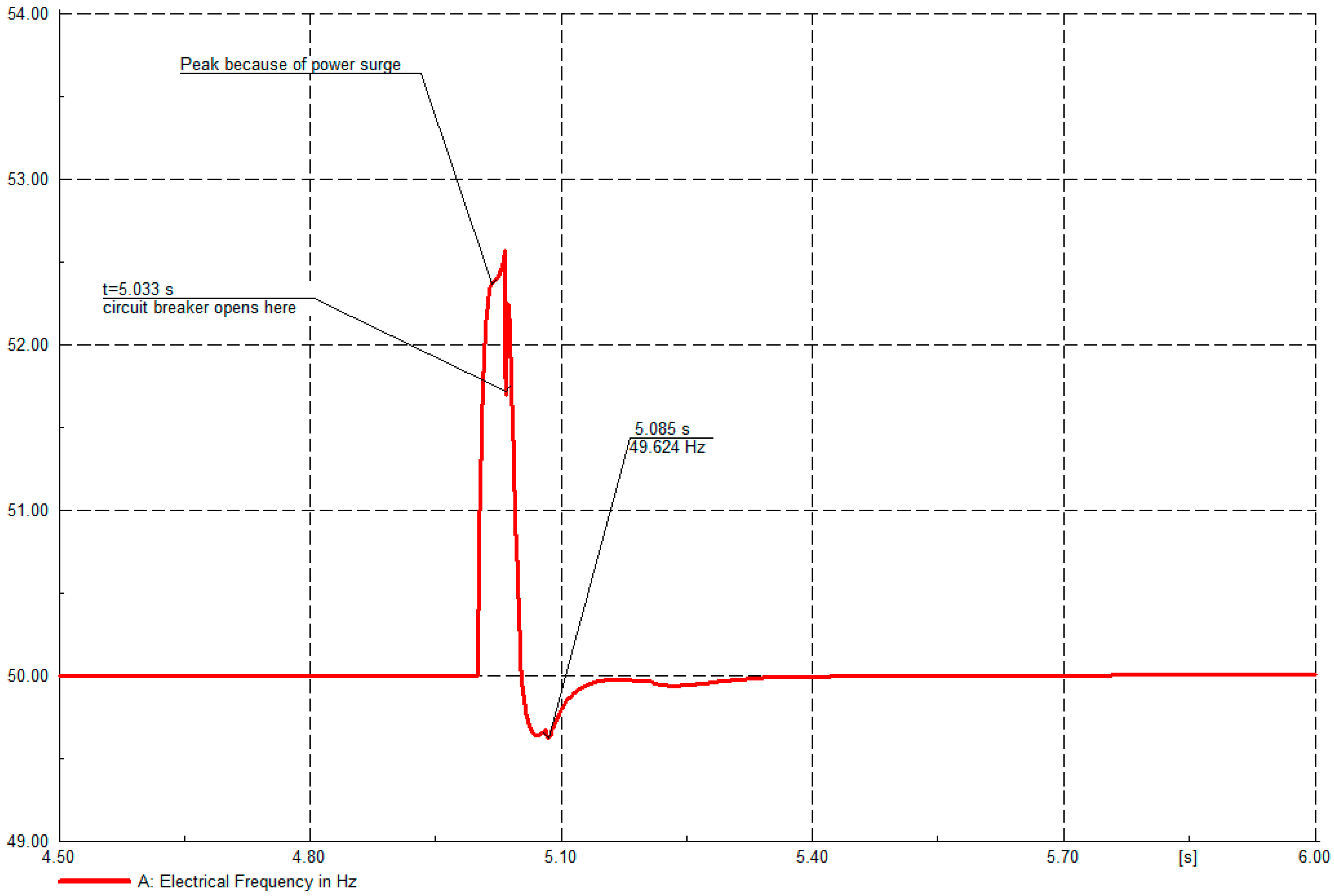
The frequency of the CIGRE distribution network at bus RE in the grid connected and islanded mode is shown in
Figure 9. It can be seen that the frequency of the distribution network is 50 Hz in the normal operating condition. The deviations in the frequency can be seen at the time when the distribution grid is disconnected from the transmission grid and these deviations are controlled within very short periods by using the developed controllers. Even though the developed controllers have ensured the controlled operation of the islanded MG, the islanded operation of the MG is not as efficient as that of the grid connected operation [
27], and batteries run out of energy since they discharge in a relatively short time. Therefore, the islanded portion of the CIGRE network must be reconnected to the grid. This can be done if the voltage, the frequency, and the phases of the two systems (i.e., the transmission grid and the distribution grid) are synchronized [
28]. In order to do so, the control system of BESS1 needs to be switched from VF mode to PQ mode. The switching of the controller from VF to PQ mode is according to grid reconnection detection [
7].
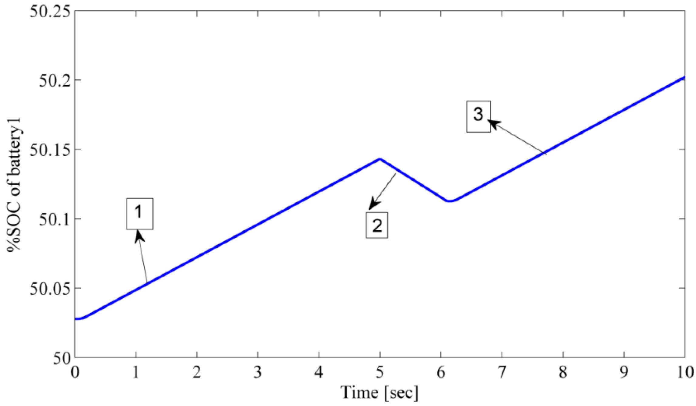
Figure 10 shows the different modes of the operations of BESS1 at different times. The percentage state of charge (SOC) of BESS1 is presented in this figure for the different operating modes. Point 1 in
Figure 10 shows that BESS1 charges for a certain time period (i.e., PQ control mode), Point 2 shows that BESS1 discharges when the distribution grid is islanded from the transmission grid (i.e., VF control mode) as it is responsible for controlling the frequency and the voltage of the network. A VF controller is developed with the frequency control priority so it mainly injects active power in case of islanding [
7]. If the initial percentage SOC of BESS1 is less than the lower activation limit (i.e., 20%), the VF controller cannot be assigned to it because it lacks the specific amount of the active power in order to maintain the frequency. Point 3 in
Figure 10 presents the case when BESS1 is again charging when the controller is switched from the VF mode to PQ mode when the distribution grid is reconnected back to the transmission grid.


