Abstract
Measurement errors of a capacitive voltage transformer (CVT) are relevant to its equivalent parameters for which its capacitive divider contributes the most. In daily operation, dielectric aging, moisture, dielectric breakdown, etc., it will exert mixing effects on a capacitive divider’s insulation characteristics, leading to fluctuation in equivalent parameters which result in the measurement error. This paper proposes an equivalent circuit model to represent a CVT which incorporates insulation characteristics of a capacitive divider. After software simulation and laboratory experiments, the relationship between measurement errors and insulation parameters is obtained. It indicates that variation of insulation parameters in a CVT will cause a reasonable measurement error. From field tests and calculation, equivalent capacitance mainly affects magnitude error, while dielectric loss mainly affects phase error. As capacitance changes 0.2%, magnitude error can reach −0.2%. As dielectric loss factor changes 0.2%, phase error can reach 5′. An increase of equivalent capacitance and dielectric loss factor in the high-voltage capacitor will cause a positive real power measurement error. An increase of equivalent capacitance and dielectric loss factor in the low-voltage capacitor will cause a negative real power measurement error.
1. Introduction
A capacitive voltage transformer (CVT) is widely used in high-voltage (HV) and extra high-voltage (EHV) systems instead of a traditional voltage transformer (VT) [1,2]. A CVT’s structure can be mainly divided into a capacitive divider and an electromagnetic unit. A capacitive divider is comprised of an insulating cylinder and a series capacitors inside of it. An electromagnetic unit is comprised of a compensation reactor, a step-down transformer and a damper. A capacitive divider can first lower the system voltage as an input for an electromagnetic unit. By isolation and reduction of the step-down transformer, the low voltage signals can be used for protection and measurement. Compared with a VT, a CVT has the advantages of smaller size, lower cost, and refrain from ferroresonance [3,4,5]. However, the structure of a CVT is more complicated than a traditional VT which has more measurement accuracy influential parameters, therefore a CVT has more significant measurement error and a higher probability of insulation faults.
Existing research involves CVT measurement errors concerning various factors. Reference [6] uses PSCAD (power systems computer aided design) to simulate the measurement error of CVT under different harmonic conditions. References [7,8] propose a CVT circuit model in harmonic conditions. After simulations and experiments, a relationship between its equivalent parameters and harmonic transfer characteristics is obtained. Reference [9] establishes the steady state CVT circuit model with emphasis on the measurement error caused by system frequency and secondary burden change. Reference [10] focuses on the measurement error caused by hysteresis characteristics of the core. It proposes an algorithm that estimates the voltage across the capacitor and the reactor by considering the effect of the hysteresis characteristics of the core and adds it to the measured secondary voltage to obtain the correct voltage. References [11,12,13] use Maxwell to study the measurement error caused by space field. The conclusions are useful for CVT parameters optimization. Beside measurement errors, plenty of studies are focused on CVT transient response. Reference [14] uses ATP-EMTP (the alternative transients program) to study CVT transient response under both system faults and ferroresonance conditions. The result shows CVT transient response is significantly relevant with CVT component parameters and system conditions. Reference [15] also bases its study on ATP-EMTP simulation and designs an effective electronic ferroresonance circuit which proves to effectively suppress low voltage transients and high voltage ferroresonance oscillations. Reference [16] proposes a new method to reduce the impact of the transient response which is based on a least squares technique. After the case study, it shows this method can minimize the impact of CVT transients.
However, research on measurement errors of a capacitive voltage transformer caused by insulation parameters variation are rarely reported. The insulation parameters of a capacitive divider include equivalent capacitance, dielectric loss factor and surface leakage current. The measurement error of a CVT is directly relevant to a capacitive divider’s insulation parameters. As a capacitive divider is exposed to atmosphere, temperature, moisture, environmental contamination, and humidity it will exert mixing effects on its insulation characteristics, leading to equivalent parameters fluctuation and further resulting in the measurement error. In this paper, a comprehensive circuit model is proposed to characterize a CVT which involves both internal and external insulation characteristics. After simulation and experiments, the relationship between measurement errors and insulation characteristics is obtained.
2. Proposed CVT Circuit Model
The structure of a CVT is shown in Figure 1. CH is the high-voltage capacitor and CL is the low-voltage capacitor. L is the compensation reactor which can be used to compensate the equivalent capacitance of a capacitive voltage divider. T is the step-down transformer and D is the damper.
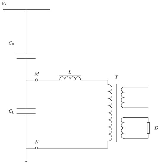
Figure 1.
Structure of capacitive voltage transformer (CVT).
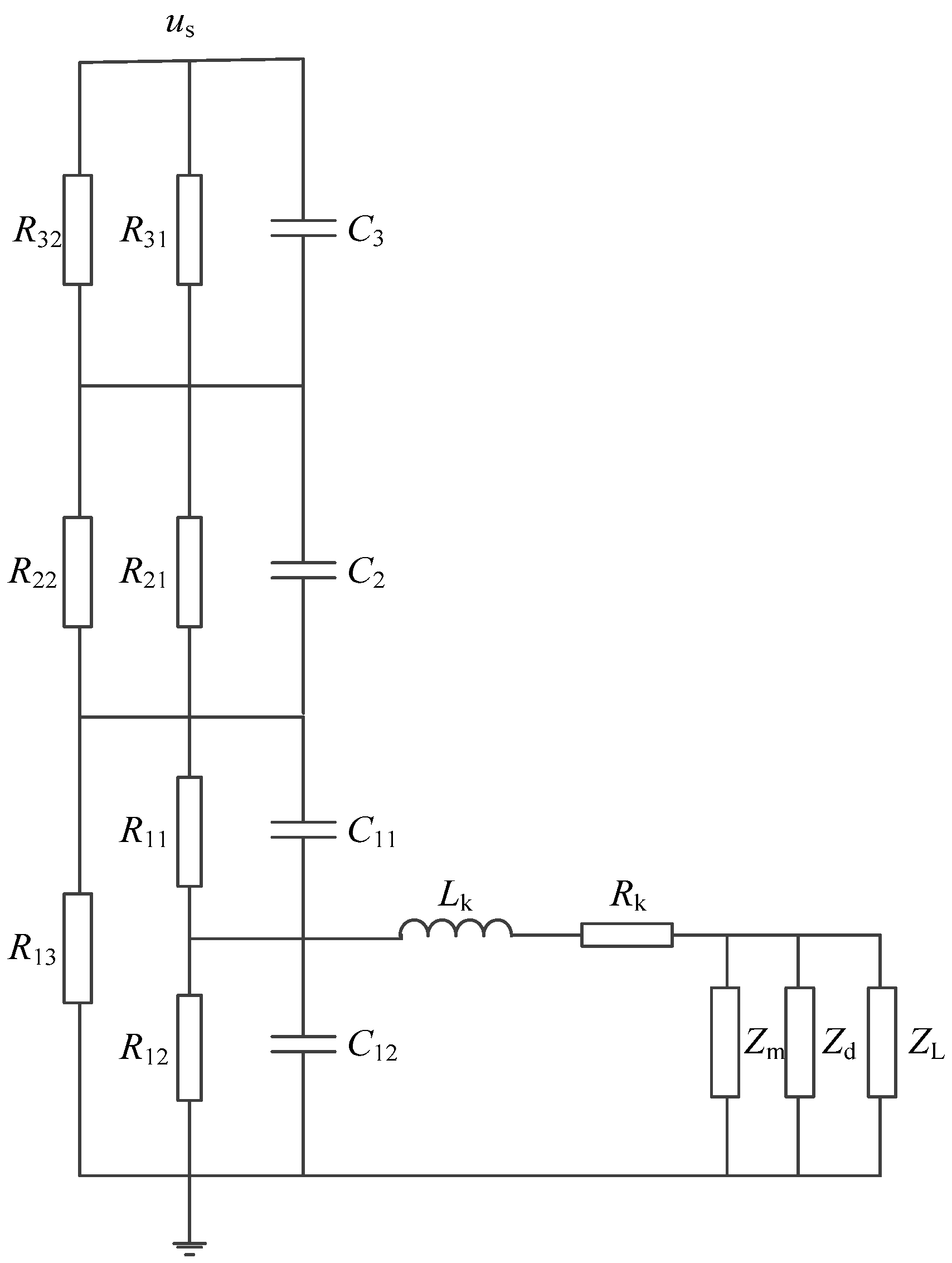
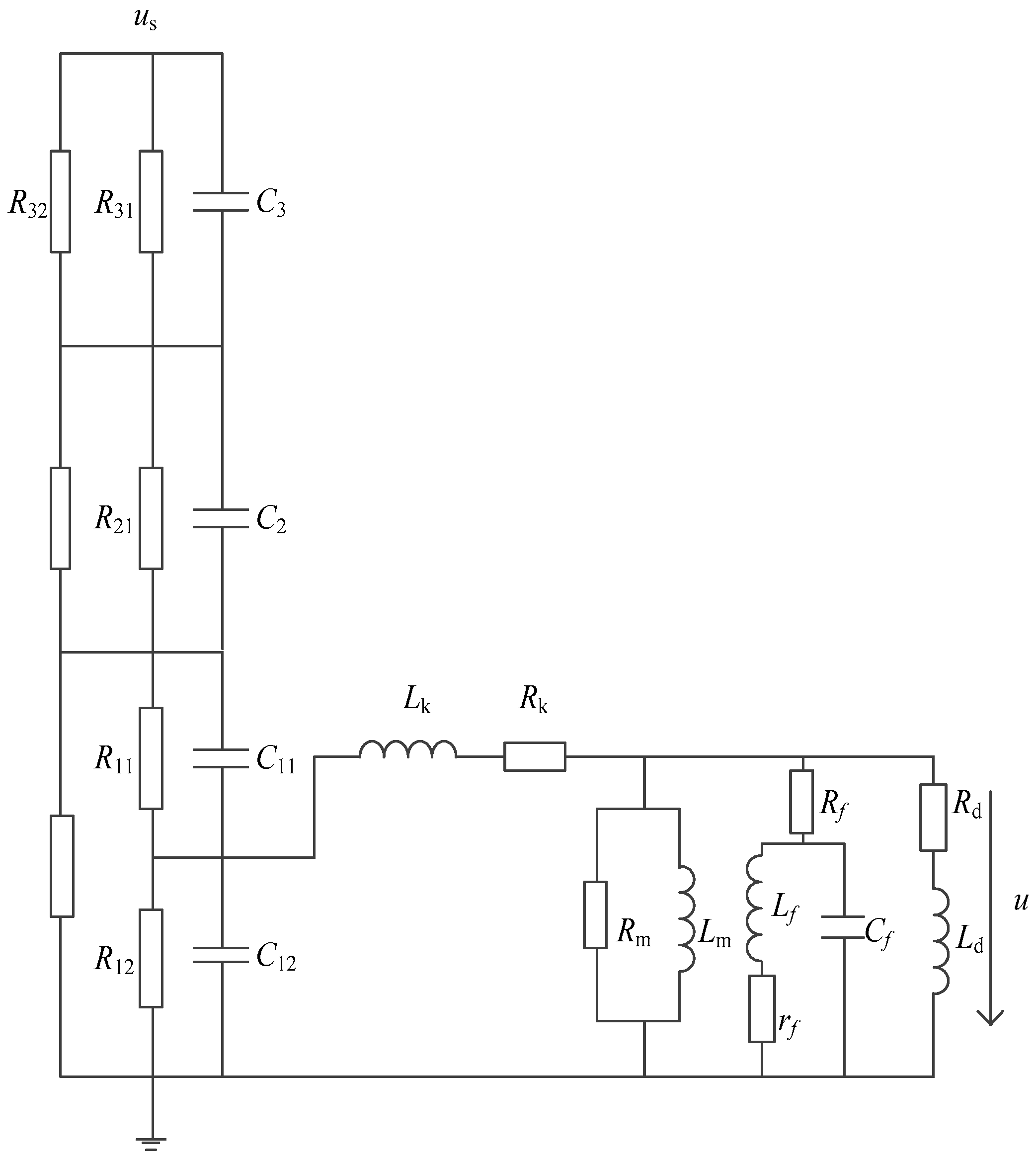
The equivalent model of a CVT’s capacitive divider is actually not purely capacitive since it has inner insulation dielectric loss and outer surface leakage current. Taking these aspects into account, the proposed CVT circuit model is shown in Figure 2.
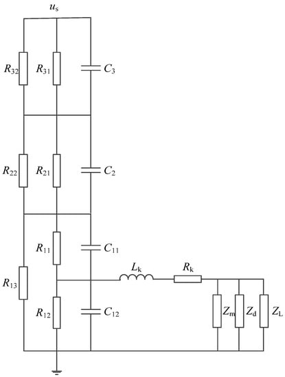
Figure 2.
Proposed circuit model of a CVT.
It is named as first, second, and third capacitor from bottom to the top in the voltage divider respectively. C11, C12, C2, and C3 are the equivalent capacitance of each segment, where C11, C2, and C3 belong to the high-voltage capacitor, and C12 belongs to the low-voltage capacitor. The main factors influencing equivalent capacitance are temperature and dielectric breakdown. Since a CVT capacitor has negative temperature coefficient, equivalent capacitance will decrease when temperature increases. Dielectric breakdown will cause a short circuit in series capacitors, which means equivalent capacitance will increase. R11, R12, R21, and R31 are the insulation resistances of each segment. Increase of the dielectric loss factor represents a decrease in insulating resistance. The main factors influencing insulation resistance are temperature and moisture in the insulation. When temperature increases, the dielectric loss of capacitor will first decrease and then increase. Therefore, the corresponding insulation resistance will first increase and then decrease. Moisture in the insulation will result in a larger dielectric loss, which means the insulation resistance will decrease. R13, R22, and R32 are the surface equivalent resistances. Increase of leakage current represents decrease of surface resistance. The main factors influencing the surface resistance is environmental contamination and humidity. When contamination and humidity in the atmosphere increases, the surface leakage current of a capacitive divider will increase, which represents the decrease in surface resistance. The electromagnetic unit, Lk, is the sum of compensation reactor reactance and leakage reactance of the transformer, which can be used to resonate with equivalent capacitance of the voltage divider C0, . Rk is the sum of tuning reactor resistance and short circuit resistance of the transformer; Zm is the excitation impedance of the transformer; Zd and ZL are the impedance of the damper and load which are recalculated to the primary side of the step-down transformer.
3. Theoretical Analysis of CVT Measurement Error
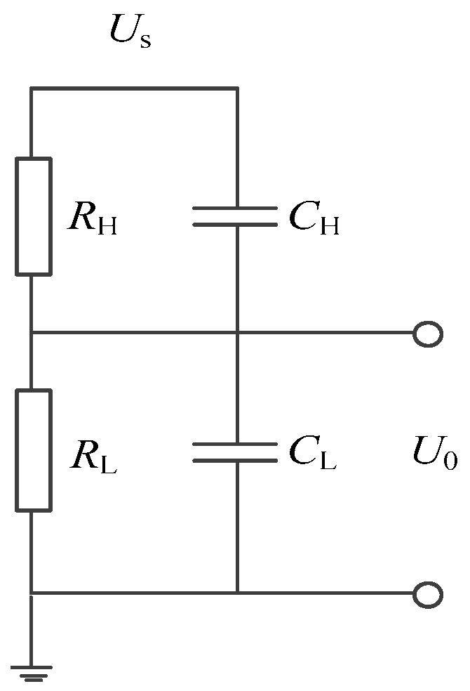
To simplify the analysis model, a high-voltage capacitor model and a low-voltage capacitor model are applied. In Figure 3, CH and RH are the equivalent capacitance and resistance of the high-voltage capacitor and CL and RL are the equivalent capacitance and resistance of the low-voltage capacitor. The Thevenin model of the capacitive divider is in Figure 4.

Figure 3.
Capacitive divider equivalent model.
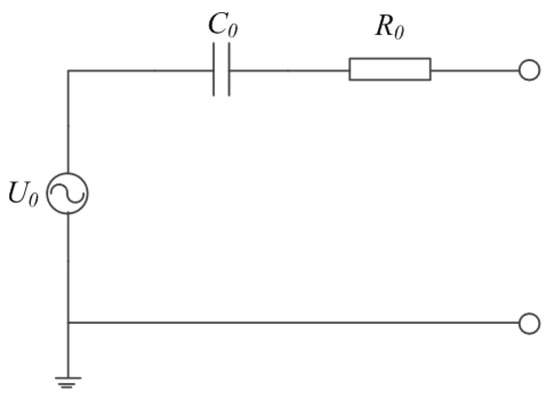
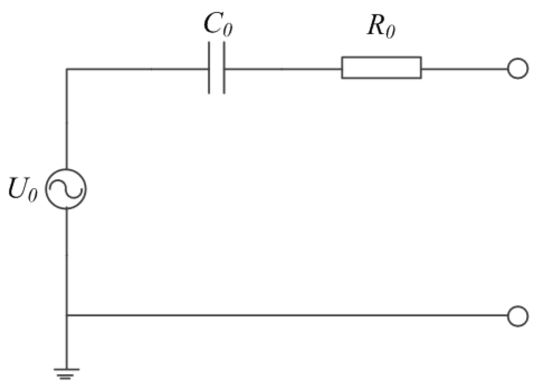
Figure 4.
Thevenin model of the capacitive divider.
Assuming system voltage is Us, the output voltage of the capacitive divider, U0, can be expressed by Equation (1),
is the dielectric loss factor which can be used to characterize the real power loss of insulating material. Substituting into Equation (1), U0 can be expressed by equation (2),
C0 and R0 can be calculated from the capacitive divider equivalent model,
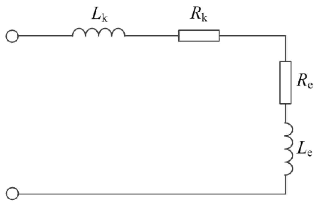
The circuit model of the electromagnetic unit is shown in Figure 5, which can be simplified to Figure 6, where Le and Re are separately the equivalent reactance and resistance of Zm, Zd, and ZL.
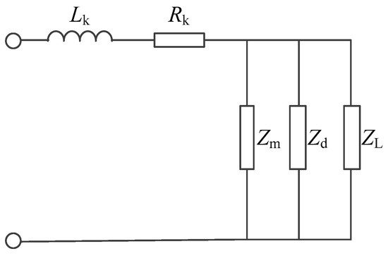
Figure 5.
Circuit model of the electromagnetic unit.

Figure 6.
Equivalent model of the electromagnetic unit.

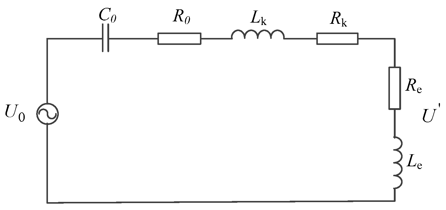
Figure 7.
Equivalent model of the capacitor voltage transformer.
The output voltage of CVT which is recalculated to the primary side of the step-down transformer can be expressed by Equation (5),
Since the main focus of this paper is on the relationship between measurement error and insulation characteristics, and can be treated as constant. If is marked as Zk, and is marked as Ze, Equation (5) can be simplified to Equation (6),
Assuming the voltage ratio of the step-down transformer is N, the output voltage can be expressed by Equation (7),
It can be concluded from Equations (6)–(7) that measurement error of the CVT is relevant with CH, , CL, . Increase of CH and will cause a positive magnitude error while increase of CL, will cause a negative magnitude error. Increase of will cause a negative phase error while increase of will causes a positive phase error. Increase of CH and CL will both cause a negative phase error.
4. Simulation of Measurement Error with Various Insulation Parameters
Since the parameters of a capacitive divider change more significantly than those of an electromagnetic unit in daily operation, the parameters of an electromagnetic unit and load are assumed unchanged in simulation. Assuming external leakage current is 0, the relationship between measurement error and insulation parameters can be obtained as the dielectric loss factor and equivalent capacitance of each capacitor are changed. Figure 8 shows the simulation model of CVT and Table 1 shows the equivalent parameters of the CVT, where parameters of the ferroresonance damping circuit and the load are recalculated to the primary side of the step-down transformer. And the voltage ratio N of the step-down transformer is 330.

Figure 8.
Simulation model of CVT.

Table 1.
CVT simulation parameters [6].
4.1. CVT Measurement Error with Different Dielectric Loss Factor
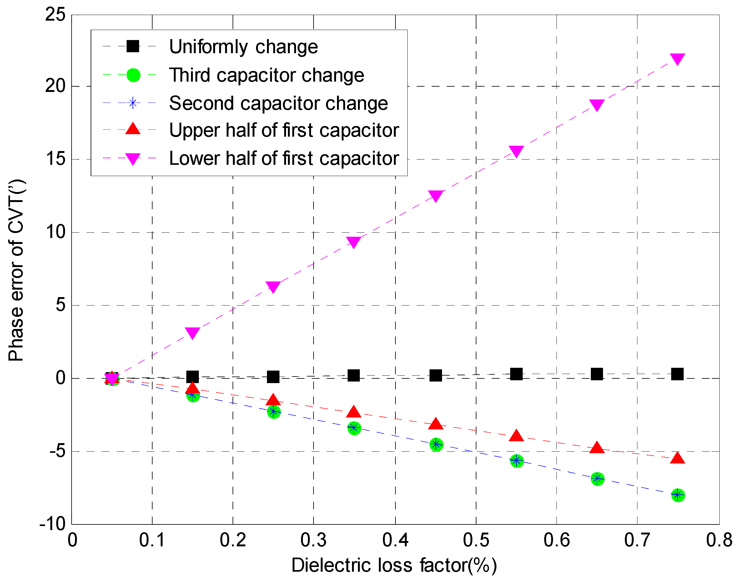
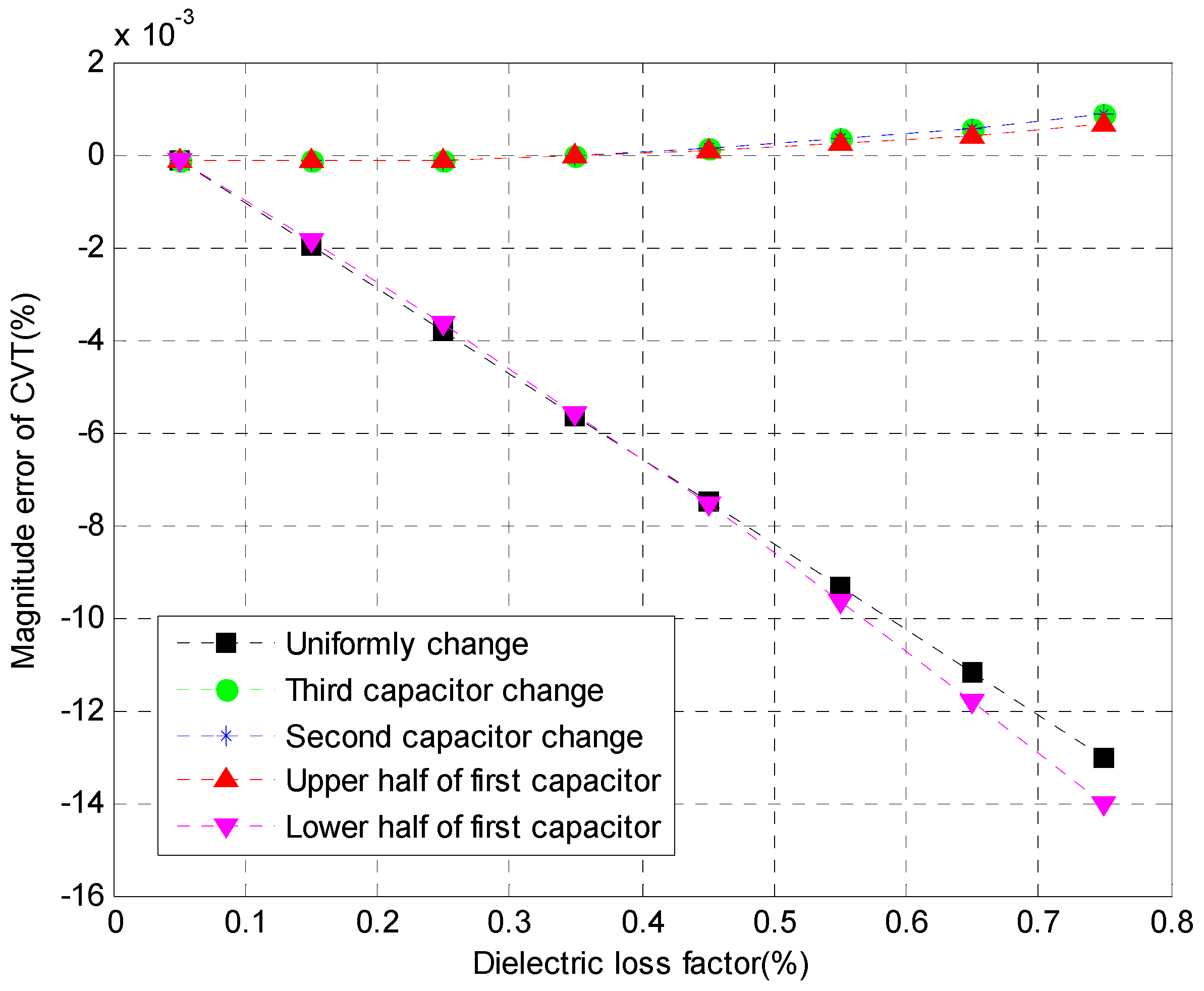
To avoid the measurement error caused by change of equivalent capacitance, the equivalent capacitance of the capacitive divider is set as constant according to Table 1. When the individual capacitor’s dielectric loss factor changes, the dielectric loss factor of other capacitors remain 0.05%. CVT phase and magnitude error with different dielectric loss factors are shown in Figure 9 and Figure 10.
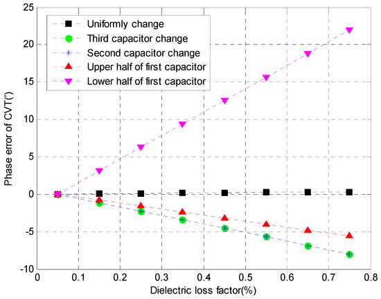
Figure 9.
CVT phase error with different dielectric loss factor.

Figure 10.
CVT magnitude error with different dielectric loss factor.
It can be concluded, that dielectric loss factor mainly affects the phase error. Measurement error caused by dielectric loss factor change in the second and third capacitor is totally the same. Increase of dielectric loss in the second, third, and upper half of the first capacitor will cause a negative phase error and positive magnitude error. Increase of dielectric loss in the lower half of the first capacitor will cause a positive phase error and negative magnitude error.
4.2. CVT Measurement Error with Different Equivalent Capacitance
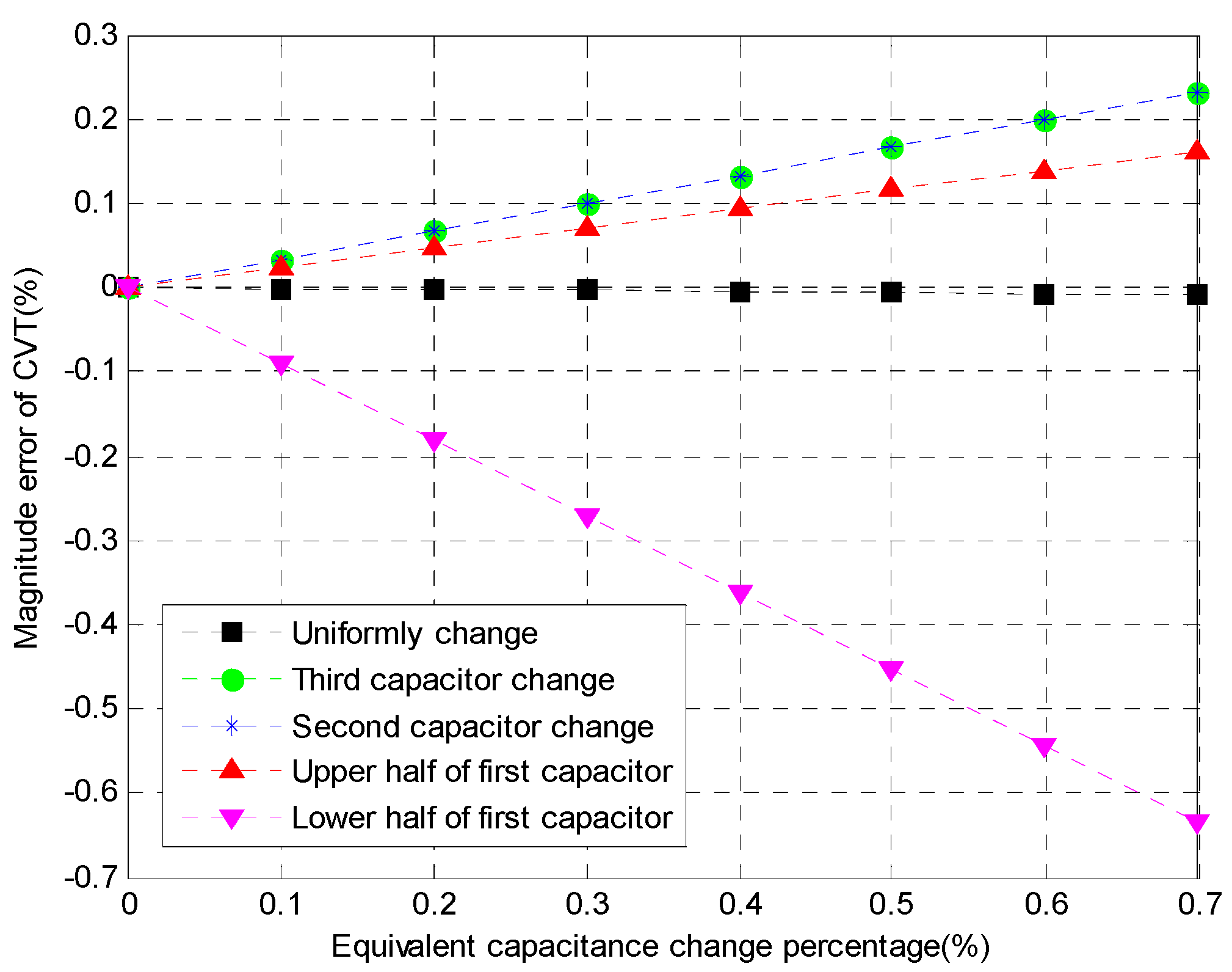
To avoid the measurement error caused by change of the dielectric loss factor, the dielectric loss factor of each capacitor is fixed to 0.05%. When individual capacitor’s equivalent capacitance varies, the equivalent capacitance of other capacitors remains unchanged. CVT measurement error with different equivalent capacitance is shown in Figure 11 and Figure 12.
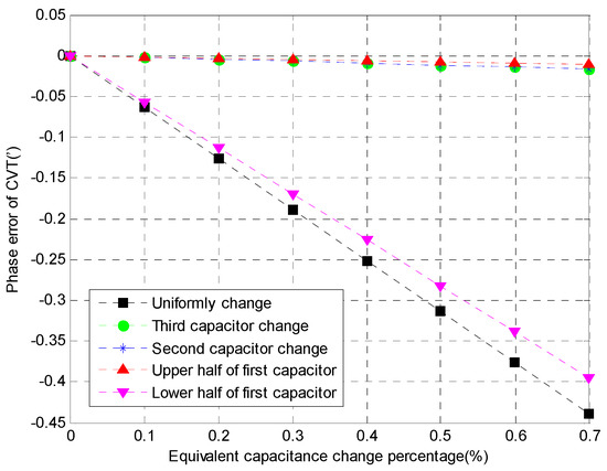
Figure 11.
CVT phase error with different equivalent capacitance.
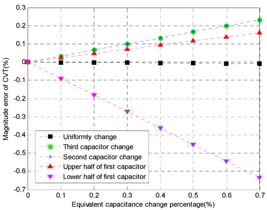
Figure 12.
CVT magnitude error with different equivalent capacitance.
It can be concluded that equivalent capacitance mainly affects the magnitude error. Measurement error caused by equivalent capacitance change in the second and third capacitor is exactly the same. Increase of equivalent capacitance in the second, third, and upper half of first capacitor will cause a negative phase error and positive magnitude error. Increase of equivalent capacitance in the lower half of the first capacitor will cause a negative phase error and negative magnitude error.
4.3. CVT Real Power Measurement Error with Different Insulation Parameters
Once the phase and magnitude error under various insulation parameters is obtained, the real power measurement error of the CVT can also be calculated. Assuming Us and U are the magnitude of the system voltage and the measuring voltage, the magnitude error can be expressed as . The phase error can be expressed as , where is the phase difference between Us and I, and is the phase difference between U and I.
Real power measurement error of the CVT can be expressed by Equation (8),
Substituting and into Equation (8), the real power measurement error of the CVT can be expressed by Equation (9),
It can be seen from Equation (9) that the power measurement error of the CVT is also relevant with the power factor of the system. If the power factor is set to 0.8 lagging, the real power measurement error under various insulation parameters can be calculated. CVT real power measurement error with different dielectric loss factor and equivalent capacitance are shown in Figure 13 and Figure 14.
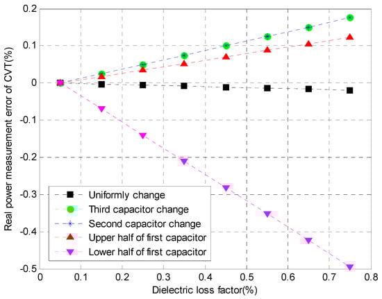
Figure 13.
CVT real power measurement error with different dielectric loss factor.

Figure 14.
CVT real power measurement error with different equivalent capacitance.
5. Experiment
Since the dielectric loss factor of a real CVT is hard to arbitrarily change, in order to better study the relationship between CVT measurement error and insulation parameters with experiments, a low-voltage CVT model is proposed. The structure of the CVT model is shown in Figure 15. Series connected capacitors are put inside an insulation cylinder to simulate the capacitive divider, and series connected resistors are in parallel with the capacitors to represent the equivalent resistive current by dielectric loss. The electromagnetic unit is equaled by the compensation reactor and the step-down transformer both having equivalent parameters. In experiment, the dielectric loss factor of the capacitive divider can easily be altered by adjusting the resistors. Phase and magnitude error of the CVT can be measured by a Lecory HDO6104 12-bit high precision oscilloscope by comparing the voltage of the CVT model and a 3 kV high accuracy class 0.1 reference VT.
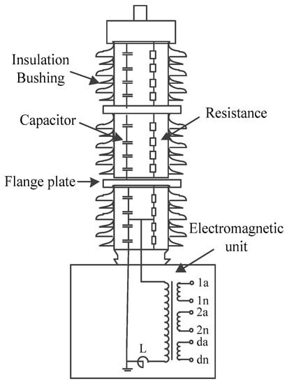
Figure 15.
Structure of low-voltage CVT model.
The real picture of low-voltage CVT model is shown in Figure 16. CVT experiment wiring diagram is shown in Figure 17.
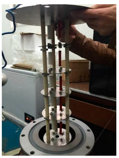
Figure 16.
Capacitive divider of low-voltage CVT model.
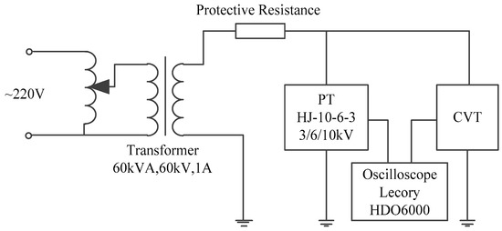
Figure 17.
CVT experiment wiring diagram.
5.1. CVT Measurement Error with Various High-Voltage Capacitor Dielectric Loss Factor
In order to eliminate the measurement error caused by dielectric loss factor change in the low-voltage capacitor, the low-voltage capacitor is fixed to 100 nF with no parallel resistance. The dielectric loss factor of low-voltage capacitor is 0.012% which can be measured with a dielectric loss meter. The high-voltage capacitor is fixed to 25 nF. The dielectric loss factor of the high-voltage capacitor with different parallel resistance is shown in Table 2.
Table 2.
Dielectric loss factor of high-voltage capacitor with different resistance.
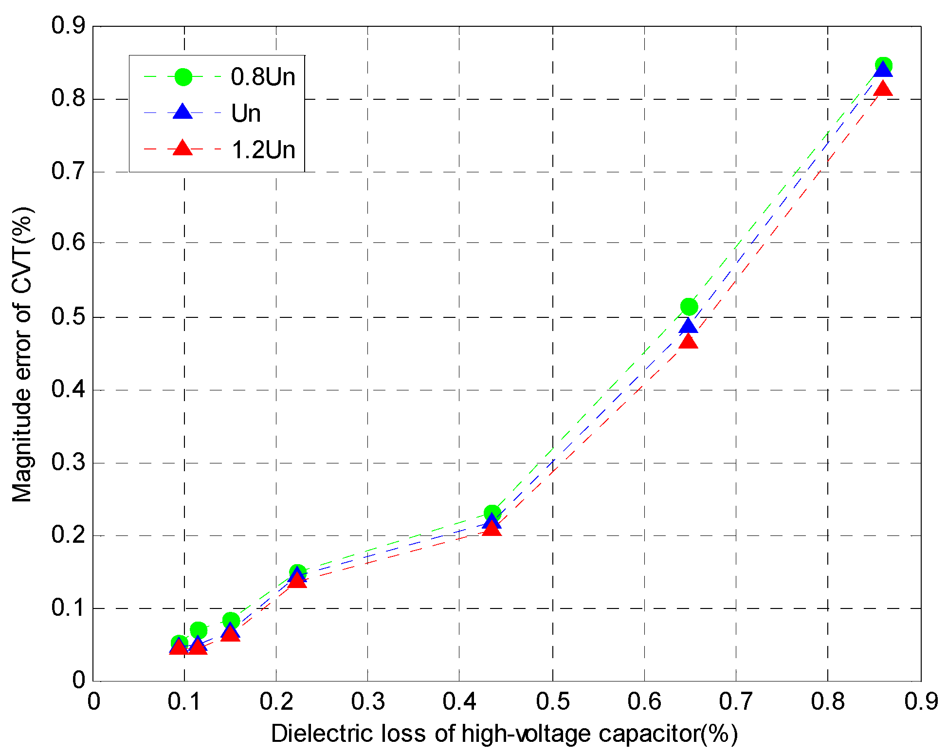
The testing voltage is 0.8, 1, and 1.2 of rated voltage (3 kV). Measurement error under various dielectric loss of the high-voltage capacitor is shown in Figure 18 and Figure 19.
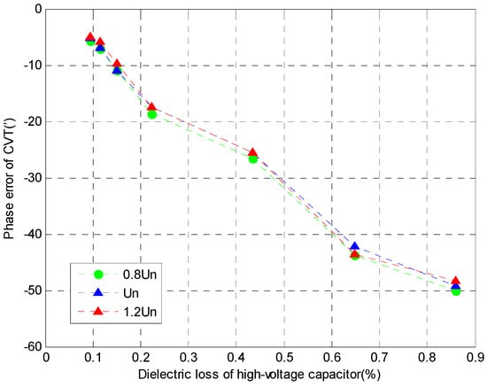
Figure 18.
CVT phase error with different high-voltage capacitor dielectric loss factor.
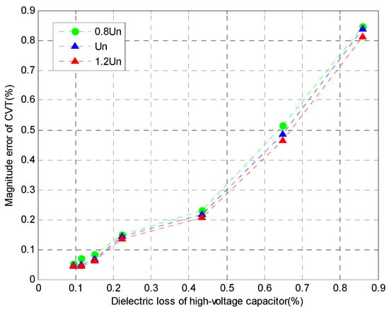
Figure 19.
CVT magnitude error with different high-voltage capacitor dielectric loss factor.
5.2. CVT Measurement Error with Various Low-Voltage Capacitor Dielectric Loss Factor
In order to eliminate the measurement error caused by dielectric loss factor change in the high-voltage capacitor, the high-voltage capacitor is fixed to 25 nF, with no parallel resistance. The dielectric loss factor of the high-voltage capacitor is 0.012% which can be measured by a dielectric loss meter. The low-voltage capacitor is fixed to 100 nF. The dielectric loss factor of the low-voltage capacitor with different parallel resistances is shown in Table 3.
Table 3.
Dielectric loss factor of low-voltage capacitor with different resistance.
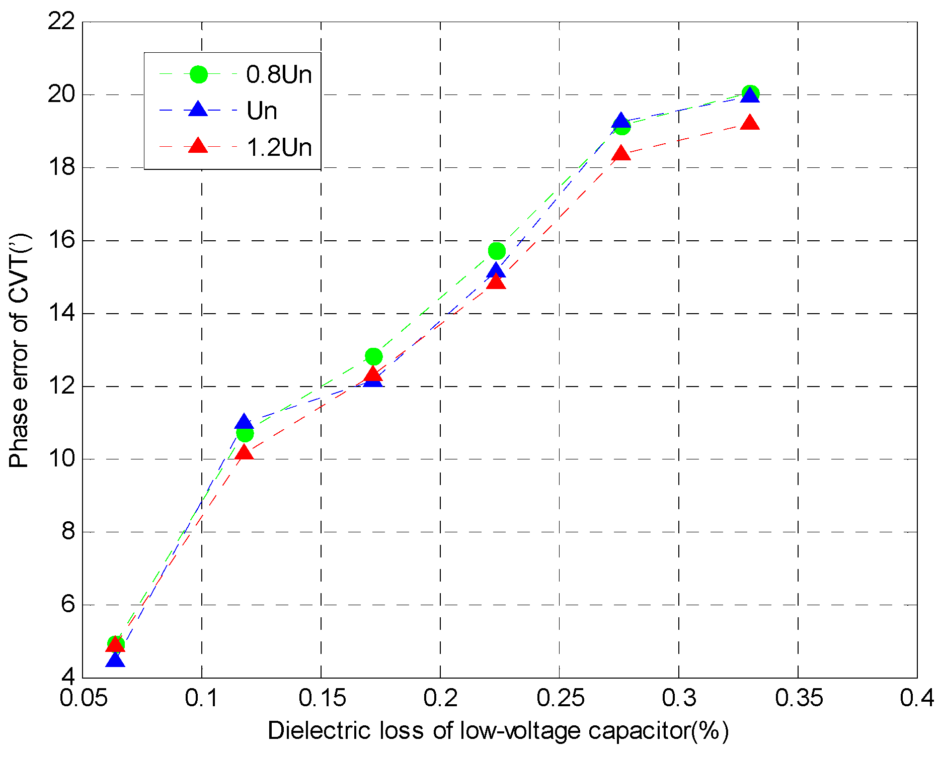
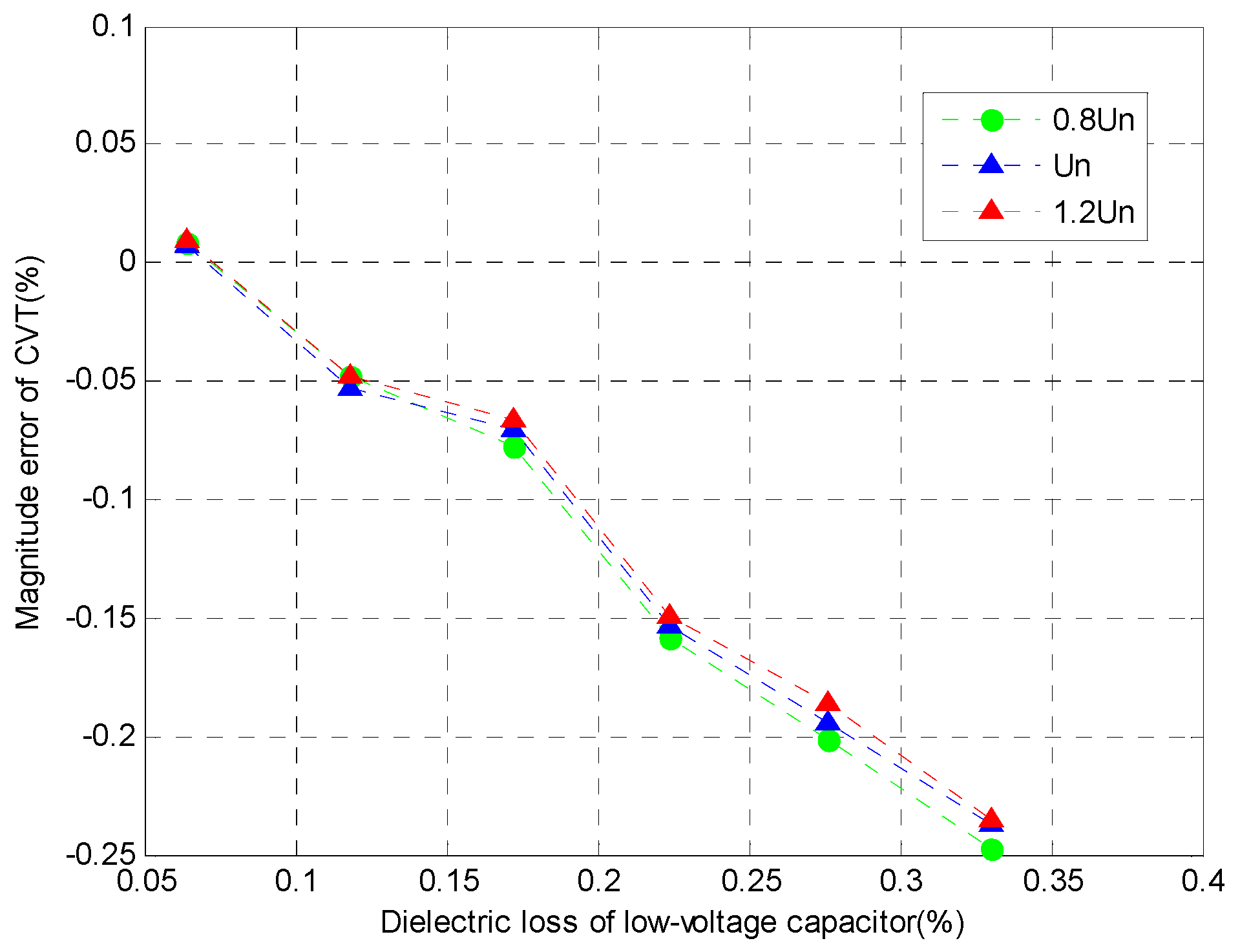
Plots in Figure 20 and Figure 21 coordinate with regulations obtained from simulation. When the dielectric loss factor of the low-voltage capacitor increases, the phase error is increasing in the positive direction while magnitude error is increasing in the negative direction. However, since the insulation parameters in the simulations and experiments are different, the specific value in experiments is not the same as in the simulations.
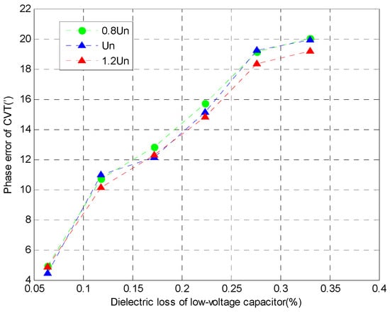
Figure 20.
CVT phase error with different low-voltage capacitor dielectric loss factor.
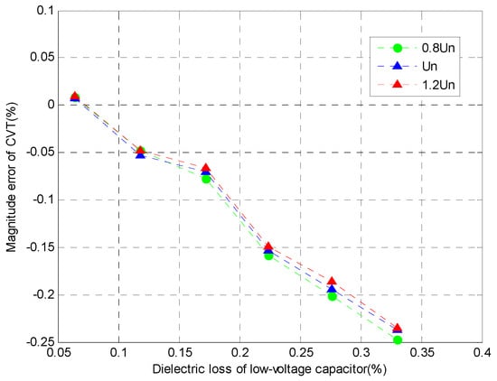
Figure 21.
CVT magnitude error with different low-voltage capacitor dielectric loss factor.
6. Conclusions
This paper proposes an equivalent circuit model to represent a CVT which incorporates the insulation characteristics of a capacitive divider. This simulation model can reflect the measurement error change caused by insulation parameters fluctuation. In order to verify the simulation results, a low-voltage CVT experimental model is proposed. After software simulations and laboratory experiments, the relationship between measurement error and insulation parameters is obtained.
Conclusions are as following. These conclusions are all straightforward in judging how the measurement error of the CVT will change according to the variation of insulation parameters and whether a certain CVT has the possibility to exceed the measurement error limit.
- (1)
- Insulation parameters fluctuation of the CVT’s capacitive divider can contribute a fairly large measurement error. Equivalent capacitance fluctuation mainly affects magnitude error, while dielectric loss factor mainly affects phase error. When equivalent capacitance changes 0.2%, magnitude error can reach −0.2%. When dielectric loss factor changes 0.2%, phase error can reach 5′.
- (2)
- An increase of equivalent capacitance in the high-voltage capacitor will cause a positive magnitude error while that in the low-voltage capacitor will cause a negative magnitude error. An increase of dielectric loss factor in the high-voltage capacitor will cause a negative phase error while that in the low-voltage capacitor will cause a positive phase error.
- (3)
- An increase of equivalent capacitance and dielectric loss factor in the high-voltage capacitor will cause positive real power measurement error. An increase of equivalent capacitance and dielectric loss factor in the low-voltage capacitor will cause negative real power measurement error.
Acknowledgments
The authors acknowledge the Funds for Innovative Research Groups of China (51321063).
Author Contributions
Lin Du, Bin Chen and Feng Yang developed the theory and performed the simulation. Kun Liu, Xianshun Chen and Fuzhou Zhang carried out the experiments. Bin Chen and Lin Du analyzed the data and wrote the paper.
Conflicts of Interest
The authors declare no conflict of interest.
References
- He, B.T.; Li, Y.Q.; Bo, Z.Q. An adaptive distance relay based on transient error estimation of CVT. IEEE Trans. Power Deliv. 2006, 21, 1856–1861. [Google Scholar] [CrossRef]
- Firous, B.A.; Majid, S.P.; Afshin, R.Z.; Reza, I. Analysis and suppression of the coupling capacitor voltage transformer ferroresonance phenomenon. IEEE Trans. Power Deliv. 2009, 24, 1968–1977. [Google Scholar]
- Yu, H.; Yang, G.; Shang, R.Y.; Chen, Y.T.; Lu, Z.M. Fault simulation and diagnostic test for abnormal voltage of secondary coil of capacitor voltage transformer. In Proceedings of the 5th International Conference on Electric Utility Deregulation and Restructuring and Power Technologies (DRPT), Changsha, China, 26–29 November 2015; pp. 1617–1623.
- Wellings, J.G.; Mortlock, J.R.; Mathews, P. Capacitor voltage transformers. Electr. Eng. 1936, 79, 577–584. [Google Scholar] [CrossRef]
- Chakrabarti, R.; Basu, S.K. Steady state theory and design of capacitor voltage transformer. IET J. Mag. 1972, 10, 153–160. [Google Scholar] [CrossRef]
- Yuan, Z.Y.; Zhao, W. Research on the capacitor voltage transformer measurement error under harmonic environment. In Proceedings of the Chinese Automation Congress (CAC), Changsha, China, 7–8 November 2013; pp. 104–109.
- Duan, X.B.; Zhu, M.X.; Hu, W.P.; Zhou, W. Key parameters affecting harmonic transfer characteristics of capacitor voltage transformer. Power Syst. Technol. 2014, 38, 3153–3159. [Google Scholar]
- Feng, Y.; Wang, X.Q.; Chen, X.M.; Wu, S.P.; Mao, A.L. Influence of circuit parameters of capacitor voltage transformer on grid harmonic voltage measurement. Proc. CSEE 2014, 34, 4968–4975. [Google Scholar]
- Sun, J.T.; Wen, X.S.; Lan, L.; Li, X. Steady-state error analysis and digital correction for capacitor voltage transformers. In Proceedings of the International Conference on Electrical Machines and Systems, Wuhan, China, 17–20 October 2008; pp. 769–773.
- Kang, Y.C.; Zheng, T.Y.; Choi, S.W.; Kin, Y.H.; Kim, Y.G.; Jang, S.L.; Kang, S.H. Design and evaluation of a compensating algorithm for the secondary voltage of a coupling capacitor voltage transformer in the time domain. IET Gener. Transm. Distrib. 2009, 3, 793–800. [Google Scholar] [CrossRef]
- Li, Z. The Optimization of Structure Parameters of Electronic Voltage Transformer. Master’s Thesis, Harbin Institute of Technology, Harbin, China, 30 June 2008. [Google Scholar]
- Li, X.; Wang, X.Q.; Wu, S.P.; Yu, C.Y. Study of additional error for capacitor voltage transformer caused by high voltage wire. In Proceedings of the Chinese Society of Electrical Engineering, Beijing, China, 21–24 November 2012; pp. 27–35.
- Feng, S.Z.; Chen, X.S.; Luo, R.X.; He, N.; Zhou, K. Simulation on influence of external electric field on error characteristics of CVT. In Proceedings of the 2016 International Conference on High Voltage Engineering and Application, Chengdu, China, 19–22 September 2016.
- Bakar, A.H.A.; Lim, C.H.; Mekhilef, S. Investigation of transient performance of capacitor voltage transformer. In Proceedings of the IEEE International Power and Energy Conference, Putrajaya, Malaysia, 28–29 November 2006; pp. 509–515.
- Jayachandra, S.; Yesuraj, D.J. Modeling and simulation of capacitor voltage transformer transients using PSCAD/EMTDC. In Proceedings of the 2011 IEEE Trondheim PowerTech, Trondheim, Norway, 19–23 June 2011; pp. 1–8.
- Pajuelo, E.; Ramakrishna, G.; Sachdev, M.S. Phasor estimation technique to reduce the impact of coupling capacitor voltage transformer transients. IET Gener. Transm. Distrib. 2008, 2, 588–599. [Google Scholar] [CrossRef]


© 2017 by the authors. Licensee MDPI, Basel, Switzerland. This article is an open access article distributed under the terms and conditions of the Creative Commons Attribution (CC BY) license ( http://creativecommons.org/licenses/by/4.0/).