Abstract
Increasing demand for rail transportation results in denser and more high-speed usage of the existing railway network, making new and more advanced vehicle safety systems necessary. Furthermore, high traveling speeds and the large weights of trains lead to long braking distances—all of which necessitates a Long-Range Obstacle Detection (LROD) system, capable of detecting humans and other objects more than 1000 m in advance. According to current research, only a few sensor modalities are capable of reaching this far and recording sufficiently accurate data to distinguish individual objects. The limitation of these sensors, such as a 1D-Light Detection and Ranging (LiDAR), is however a very narrow Field of View (FoV), making it necessary to use high-precision means of orienting to target them at possible areas of interest. To close this research gap, this paper presents a high-precision pointing mechanism, for the use in a future novel railway obstacle detection system, capable of targeting a 1D-LiDAR at humans or objects at the required distance. This approach addresses the challenges of a low target price, restricted access to high-precision machinery and equipment as well as unique requirements of our target application. By combining established elements from 3D printers and Computer Numerical Control (CNC) machines with a double-hinged lever system, simple and low-cost components are capable of precisely orienting an arbitrary sensor platform. The system’s actual pointing accuracy has been evaluated using a controlled, in-door, long-range experiment. The device was able to demonstrate a precision of 6.179 mdeg, which is at the limit of the measurable precision of the designed experiment.
1. Introduction
Existing railway networks are reaching their operational capacities due to rising global demand for rail transportation. Reasons for this include increasing international trade and changing consumer behavior due to raising environmental awareness and changes in personal mobility needs. Consequently, upgrades to the existing modes of operation and railway control systems, in the form of safer, more reliable, and more efficient trains, are required to keep up with the current growth. More precisely, new railway operation modes require not only reliable communication between rail vehicles, and continuous, accurate and robust localization (European Train Control System (ETCS) Level 0–2 [1]) of each train, but also environmental awareness in the form of Long-Range Obstacle Detection (LROD). In particular, the early detection of humans, animals, or objects on, or in the vicinity of the railway tracks can not only prevent life-threatening risks to humans but also extensive disruptions to the operation of the railway network. However, due to the high weight and velocity of rail vehicles, and the lower traction limiting the braking force, long distances are required for safe braking [2]. Given these circumstances, obstacle detection systems need to be capable of reliably detecting and positioning possible dangers at long ranges, greater than 1000 m.
Several technologies and solutions are already in use for obstacle detection in different applications, for example, in the automotive industry. However, there are several limitations to all of them restricting their direct transferability to the railway domain, as shown in Figure 1. The visualization highlights the long-range requirements for the application in railway systems in comparison to the capabilities of different sensor modalities, such as stereo vision and Light Detection and Ranging (LiDAR). Two additional solutions for detecting humans and other objects, even in challenging situations, are color and thermal cameras [3]. However, the lack of range information makes it difficult to accurately locate the detected obstacle, reducing the system’s reliability. Data driven methods can aid in providing vision based depth information at impressive ranges, but are highly dependent on training data. Stereo camera setups can provide additional depth information to the system [4] by computing the binocular disparity of an object which is observed by both cameras. As the depth resolution is dependent on the stereo baseline (the distance between the two cameras), a baseline larger than the width of the train would be required to achieve accurate enough depth measurements to be reliable for the obstacle detection process.
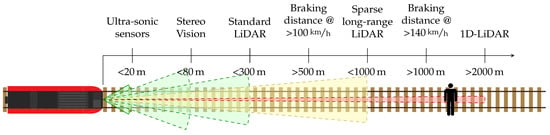
Figure 1.
Sensing range of a variety of sensors commonly used for obstacle detection and autonomous vehicles. Furthermore, braking distances at various velocities are shown. The Field of View (FoV) of the individual sensors is highlighted through their color, ranging from super wide FoVs (green) to single point measurements (red).
Additionally, radar sensors are already in use for automotive driver assistance systems and can achieve measurement ranges above 1000 m. As they rely though on the reflection of emitted radio waves from all target objects, they are limited to special radar reflective materials, such as metal, and sufficiently large targets, and are therefore not suited for detecting generic unknown obstacles at such distances.
Currently available dense LiDAR sensors can sample their environment accurately enough for detecting objects, by emitting multiple beams of light and observing their reflections, but are typically limited to a range under 300 m. Sparse long-range LiDAR systems exist [5], though with reduced measurement density and increased measurement times, making them unsuitable for detecting objects while the sensor is moving at high speed.
The limitations of the aforementioned sensor systems make it clear that, in order to achieve an accurate detection and localization of obstacles at long range, it is necessary to integrate various sensor modalities into a complete detection system.
To address these limitations, we propose to develop a combined camera-LiDAR sensor system capable of providing accurate and reliable obstacle detection and positioning at large distances. The proposed system consists of a wide-angle overview camera observing the train’s entire FoV (the tracks and their immediate vicinity lying ahead of the train), as shown in green in Figure 2. Based on the vision system as well as a known track map, a possible Region of Interest (RoI) can be determined (shown in yellow) within which possible obstacles might be located. Additional cameras and LiDAR sensors are then supposed to detect these obstacles at high range within this RoI. 1D-LiDAR sensors exist with multiple kilometers of range. However, these sensors are only capable of measuring a few points per second and can therefore not detect objects on their own. Instead, we propose to couple such a sensor with a high focal length camera to produce an image with combined depth measurement. Due to the very limited FoV of this setup, as well as the long measurement time of the laser, an active vision approach is required. The system needs to be placed on a gimballing platform capable of orienting the combined sensor setup at possible targets located within the specified RoI. This is shown in the centre of Figure 2 where the FoVs of two sensors are actively being angled at the rail tracks ahead. As especially the FoV of the 1D-LiDAR is severely limited, it is crucial to be able to control the exact orientation of the setup in order to reliably hit targets with the laser beam, even at distances above 1000 m. The actuation system of such an active vision sensor setup is therefore the focus of this research work.
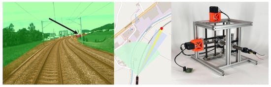
Figure 2.
Long-Range Obstacle Detection systems need to focus their sensors on targeted Regions of Interest, shown in yellow and red (arrow), in the vicinity of the railway track. The change of attitude of individual sensors is shown in the centre image, to focus the sensors on possible obstacles. This can be done using a high precision pointing mechanism as shown on the right.
To realize this, our work consists of the development and evaluation of a novel pointing mechanism suitable to our target application. More precisely, the contributions of our development are the following:
- A novel, high precision, versatile, low-cost pointing mechanism.
- An evaluation of the pointing resolution and accuracy of the developed system, based on extensive indoor tests in a controlled environment using optical equipment, as well as a direct comparison to commercially available gimbals.
- An investigation into the remaining sources of errors, a thorough evaluation of their effects, and proposals for their future mitigation.
- A novel proposal for an integrated sensor solution to Long-Range Obstacle Detection, consisting of custom high-precision hardware and specialized sparse long-range sensors.
The developed pointing mechanism could potentially be used for a variety of applications, ranging from active vision when combined with a camera, such as used in surveillance, astronomy, or cinematography, through measurement tasks, when combined with or Laser or Radar for example for Geomatics, or for communication systems where they orient antennas or lasers for long-range data transmission.
For our target application of Long-Range Obstacle Detection for railway systems, it is important to reliably detect and localize objects at greater distance (>1 km) requiring an orienting system with sufficient precision and accuracy to hit a target using the 1D-LiDAR at these ranges. The major requirement to our developed system is therefore the pointing accuracy and precision. Precision here refers to the spread of the orientation error when aiming at a specific target. Accuracy on the other hand refers to how true the observed orientation of the gimbal is compared to its actual orientation. The average human width at shoulder height (bideltoid shoulder breadth) worldwide exceeds 400 mm for both men and women [6]. A pointing accuracy of at our target range of 1500 m should therefore be a minimum requirement. This translates to a maximum angular accuracy of 7.639 mdeg, rounded down to 7.5 mdeg.
Further technical requirements to the developed system are a range of motion of at least 60 deg to cover the train’s FoV as well as a payload capability of 2 kg. An additional requirement to the overall project of developing this device is the low target price. This is limited to $1000, necessitating the development of a low-cost solution, utilizing mostly common and cheaply available components.
The remainder of the paper is organized as follows: In Section 2, an extensive summary of related work in LROD and high-precision pointing mechanisms is provided. Furthermore, in Section 3, our system for precise pointing is described in detail. Experiments, results, evaluation, and a discussion thereof are given in Section 4 and a brief cost analysis in Section 5. Finally, Section 6 provides a conclusion with an outlook on future work.
2. Related Work
2.1. Railway Obstacle Detection
Long-Range Obstacle Detection for railway applications is an ongoing challenge and the focus of much ongoing research. Many approaches for purely vision-based object detection in the railway domain have been developed [7,8,9,10,11,12,13,14,15,16,17,18,19,20,21]. These typically employ machine learning and computer vision methods for object or anomaly detection or 3D-Vision methods for detecting physical intrusions into the vehicle’s path. However, most of these do not provide any in depth information. Some approaches employ machine learning or data-driven methods for depth estimation with reasonable success [22,23], even for distances over 500 m [24], but this is very much dependent on training data. Another approach is to deduce the distance based on the parallax of the tracks [25,26]. Ristić-Durrant et al. [3] provide an in-depth analysis of purely optical-based object detection systems for railways and compare their performances and limitations. Simple stereo camera setups can provide dense and accurate depth information, but due to the limited baseline only at a short range of approximately 80 m [4,27,28,29]
Ukai [30] employs an active vision approach to extend the range of vision-based approaches. In further research, this is fused with Radar sensors for depth information [31,32]. However, the setup only has a depth estimation range of 200 m with a resolution of over 2.5 m on top of the limitations of Radar regarding target materials, limiting its usability for high-speed railway applications. Similarly, Radar is also fused with fixed cameras or stereo cameras [33].
Several approaches employ thermal cameras as an easy means of detecting a variety of objects in the vicinity of the railway tracks [34,35]. These are especially beneficial in low-light situations or for detecting humans or animals due to their body heat. However, these approaches fail to detect obstacles that have the same temperature as their environment (e.g., fallen trees) and are also unable to provide any depth information. A combination of RGB and thermal cameras can provide more reliable object detections, especially in low light situations, but obtaining range information is still difficult, even when employing machine learning approaches [36].
Ristić-Durrant et al. [37,38,39,40] have developed an advanced sensor setup, by combining a multi-baseline stereo camera setup with a thermal camera and a dense LiDAR scanner to detect objects on the tracks at ranges approaching the 1000 m mark. Fusing a simple camera and a LiDAR scanner [41,42,43,44,45] has shown promising results at ranges between 50 m and 300 m, depending on object sizes.
2.2. Long-Range Obstacle Detection
LROD has also been in development outside the railway industry. For example, it is used in the field of remote sensing, where simple vision-based object detection can be performed at a long range through the use of super-resolution cameras or super-resolution post-processing using deep learning [46]. In this case, challenges arise from the processing of the large, high-resolution images in a timely manner [47,48,49,50].
Prior knowledge about the kind of objects that could be present in the camera’s field of view can significantly improve the long-range detection process, for example, for airplanes on a blue sky [51] or vehicles [52] on land.
Due to their dense depth maps and comparatively cheap hardware setup, stereo cameras are one of the most commonly used methods for tracking objects and their depth. In several setups, ranges between 150 m [53] and 300 m [54,55,56,57] have been be achieved if the camera baseline is sufficiently large. Deep-learning based stereo vision approaches can improve the depth estimation results but are limited in increasing the maximum range [58,59,60].
Detecting far-away objects in LiDAR is challenging, as the point clouds become sparse at long ranges and do not provide a sufficient amount of information to be able to distinguish individual objects.
Fusing camera data with other sensor modalities can equally improve the LROD performance, but this is still limited to the range of either sensor. Various combinations have been tested, such as combining Stereo Vision and LiDAR [61,62] or Radar [63]. Special long-range LiDAR sensors are in development, but still, only rarely reach distances beyond 200 m [5].
1D-LiDAR sensors can measure over much greater distances [64], reaching multiple kilometers. These sensors, however, do not provide enough data to be able to detect objects on their own and therefore need to be intelligently fused with other modalities and orienting mechanisms to provide satisfactory results.
2.3. Pointing Mechanisms
The various uses of pointing mechanisms and their specific requirements have led to the development of a multitude of possible orienting device designs and the respective selection of mechanisms, actuators, and sensors. The multitude of gimbal designs can be classified according to their mechanical setups, their type of actuators, their degrees of freedom or whether they orient the actual sensor, or just the optical path of the sensor setup, for example, through a mirror [65]. Most commonly, orienting devices are classified according to their mechanical setup into serial, parallel, or spherical mechanisms, as described in the following section.
Serial Mechanisms: The most common design in commercial gimballing systems consists of a serial mechanism, which places rotary actuators at the joints, typically on orthogonal axes, to achieve the largest possible workspace, as seen in Figure 3a. The disadvantage of this design is a limited accuracy, as weight and therefore the load on individual joints adds up from stage to stage and errors accumulate. Approaches to creating high-precision serial gimbals are the utilization of high-precision components, such as actuators, bearings, and encoders, materials, and manufacturing techniques. This can result in high pointing accuracy, but also high manufacturing costs [66,67,68,69]. A common problem in such mechanical apertures is the backlash, which occurs when there are small gaps or clearances between mechanical parts, which lead to a loss of motion or no transfer of force from one part to the next. This, for example, is introduced, for example, by reduction gears [70], but can be compensated using springs [71] or flexure hinges [72]. A further mechanical analysis of joint clearance influences is done by Bai et al. [73]. However, these solutions typically result in more expensive manufacturing and higher required actuation forces.
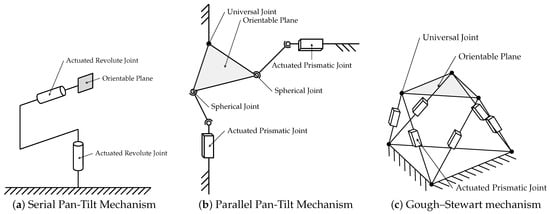
Figure 3.
Kinematic visualization of the most common pointing mechanism designs consisting either of (a) serial or (b,c) parallel mechanisms.
Instead of placing sensors directly on the orientation platform, mirrors can be placed there to only adjust the optical path of the sensors [74,75]. While this lowers required payload capacities and may allow for a larger range of motion, it introduces difficulties in controlling the system and promotes errors through sensor and axis misalignment [76] which need to be compensated for. Additionally, some sensor modalities, such as certain laser based devices, do not work using a mirror. Furthermore, different ways of actuation have been proposed either to save weight or to perform in particular environments, such as underwater. The use of pull-cables to actuate the different gimbal axis has been proposed multiple times [77,78], as well as the use of piezo-actuators for single Degrees of Freedom (DoF) gimbals [79]. However, the typical setup of two or three orthogonal axes has several shortcomings, such as singularities, gimbal-lock [80], and limited space for sensors, whose special designs aim to overcome, for example, through the use of more joints at non-orthogonal angles [81]. These solutions in turn have their own limitations, such as more mechanical joints, which due to their individual clearances may result in larger accumulated errors.
Parallel Mechanisms: parallel variants have been developed in response to the numerous shortcomings of serial pointing mechanisms. In these, several joints and actuators are placed in parallel, resulting in more complex kinematics and control methods, but also the possibility to design specific dynamic capabilities of the system. One example of parallel mechanisms is the OmniWrist III [82], whose kinematics and control have been the focus of extensive research [83,84,85,86,87]. As the proposed application is a laser communication system [88], it has also been proposed to use Bragg Cells for precise beam steering [89,90,91], in combination with the OmniWrist III, to achieve high-precision and a high range of motion [92]. Another variation of these mechanisms places the sensor setup on a universal joint and attaches linear actuators to it either in the form of push rods [93,94,95,96,97] (Figure 3b), pulleys [98,99] or pneumatic muscles [100] to orient the platform.
Flexural hinges, which connect rotary motors to the gimbal platform, can also provide beneficial dynamic properties in such a setup [101], while flexure hinges instead of a universal joint greatly benefit the system’s accuracy by limiting backlash [102,103]. Such a setup can also be extended to stereo vision, where both cameras need to be moved parallel to each other around their centers [104]. Gough–Stewart platforms (Figure 3c) and variations thereof feature more than the two or three DoFs required for a typical pointing mechanism but are equally often used for this purpose [105,106,107,108,109,110,111]. Piezo-actuators in the legs of this type of platform can provide high accuracy, but only a limited range of motion. The combination of multiple actuators in each leg can incorporate the advantages of both [112]. Furthermore, different leg designs for this platform approach, using a variety of actuators and featuring different kinematic characteristics [113,114,115,116,117,118,119,120,121], have been proposed, but few have actually been manufactured and tested [122]. Another possible improvement to the Gough–Stewart platform is the use of flexure hinges to reduce backlash and nonlinear friction [123]. Placing additional constraints on the system, for example, by fixing one of the joints, has also been suggested as a way to improve the controllability of the system [124].
A special set of tip-tilt parallel mechanisms has been developed for the use in satellites, where a high-precision but low range of motion is required. These typically employ flexure hinges, as these provide no friction, backlash, or wear, and a high-accuracy actuation part, such as piezo-actuators [125,126,127], electromagnets [128,129,130] or servos [131]. However, the use of such flexure hinges can also lead to problems such as the distortion of the mirror surface at larger deflections [132]. Using a flexure ring instead of individual hinges attached to the mirror can compensate for this [133].
Further variations on parallel gimbal platforms using various actuating arm designs include the use of three rotating legs to simulate the three DoF motion of human eyes [134], and installing flexure hinges on the actuating legs used to carry the large load of a rocket engine [135]. For underwater usage, it is beneficial to have all actuators in a single physical location to simplify the water-proofing process. To solve this issue, a specific 3DoF gimbal has been developed [136], featuring pan, tilt, and zoom motions, or similarly featuring only 2DoF [137]. Additionally, several more theoretical designs, which have not been tested, have been proposed and their dynamics analyzed [138,139,140,141,142].
Parallel gimbal mechanisms are also often used in Micro-Electromechanical Systems (MEMS) applications [143] to tilt mirrors found in image projectors and LiDAR devices, though again with a very limited range of motion.
Parallel gimbal designs offer the possibility of designing complex kinematic mechanisms for special target applications. However, these designs typically require a larger number of joints and their respective possibilities for backlash and special, expensive actuators, such as piezoelectric actuators or linear motors. Furthermore, their kinematics cannot be easily derived, making precise control mechanismsand active stabilization more complicated.
Spherical Mechanisms: A niche group of pointing mechanisms consists of spherical mechanisms. For the use as an animatronic eye, spherical cameras can be suspended in a fluid and be actuated using electromagnets [144]. This allows a highly dynamic motion but does not feature precise pointing control. Special motor designs with multiple DoFs can also be used as spherical actuators. This can be achieved through special rotor/stator designs [145,146,147,148] or ultrasonic motors [149] but limits the available payload capacity, space for sensors and overall range of motion of the system.
Even though a large variety of gimbal designs exists, most inaccuracies stem from the same sources. Fisk et al. [150] analyze possible sources of error, such as runout of bearings, non-orthogonality of axes, or the misalignment of other positioning sensors. Sweeney et al. [151] provide a set of general design rules for high-precision pointing mechanisms. These focus though on classical serial and parallel mechanisms and mainly focus on utilizing expensive and high-quality components.
The gimbal developed as part of our research can be assigned to the category of serial gimbals, as one actuation stage is based on the other. Through the use of reduction gears and lever mechanisms, the actuator and encoder resolution can be down-stepped significantly, increasing both the system’s accuracy and precision. The separate mounting points for the payload carrying joints, independent of the actuators, partially isolate influences of backlash onto the orienting platform.
A detailed overview of proposed gimballing mechanisms is given in Table 1. This table shows both commercially available orienting mechanisms and proposed mechanisms from the available literature.

Table 1.
Overview of existing gimbal mechanisms from commercial suppliers and research. The individual specifications are compared with our requirements to highlight that no system can fulfill them within the specified price range. For many mechanisms, exact manufacturing costs are not known. Based on the depicted components, a rough price range is estimated as $–$$$. Most systems have different ranges of motion per axis. As pan is the most relevant axis to us, in those cases, only the pan range of motion is listed.
3. Methods
In this section, the developed design is introduced. First, we explain the general kinematic setup, consisting of an XY-Table and a double gimballed sliding lever setup. We then elaborate on our selection of mechanical actuators and transmission mechanisms and derive the overall system kinematics. By using integrated position encoders and custom control electronics, the system can be controlled in a closed-loop manner.
3.1. Proposed Orienting Mechanism
The Computer-Aided Design (CAD) of the most relevant sections of our gimbal is depicted in Figure 4. The central part of our proposed mechanism is the double gimbal lever system, which transforms a 2D translation from our actuators into a full 3D rotation. A solid shaft acts as the major orientation component at the core of this design, rotating around the center gimbal/universal joint while being actuated by the other one. The strength and extension of the rod give few limitations to the available space and carryable weight. Consequently, various sensors can be mounted at the end of the shaft with no interference with the gimbal frame.
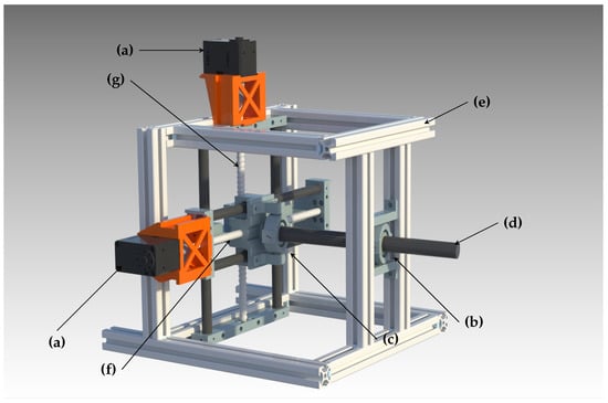
Figure 4.
Full system CAD: (a) Dynamixel servo motors; (b) frontal universal joint with linear sliding bearing; (c) second universal joint; (d) central lever shaft and sensor mounting point; (e) system frame; (f) XY-Table pan axis and ball screw; (g) XY-Table tilt axis and ball screw.
The lever not only performs the task of acting as the rotation platform but also serves the function of a mechanical reduction, reducing a longer low-torque motion into a shorter high-torque motion, thus decreasing the actuated step size and increasing the system’s precision.
The actuation of the proposed double gimbal lever system is performed using the XY-Table, a part commonly found in 3D printers or Computer Numerical Control (CNC) machines. The mechanism consists of two orthogonal linear actuators that translate a working plane along two separate axes. Most commonly, for CNC machines, a workpiece would be mounted to this plane and passed through a mechanical processing procedure, such as a mill or lathe. The widespread use of this mechanism makes it possible to easily obtain high-quality and low-cost price components to assemble this subsystem and integrate it into our design.
The central lever and the XY-Table are combined using the second universal joint, through which the lever endpoint is attached to the actuation plane of the motorized table. As a consequence of this arrangement, one endpoint of the central shaft is always located in the actuation plane, and the rotation point of the lever is locked in the platform frame using the front gimbal, resulting in a rotation motion around the latter. To adjust for the distance variation between the two gimbals, the former includes a sliding bearing that enables the central lever to move inwards and outwards. Additionally, this means that the sensor setup does not perform a pure rotation, but a translation along the pointing axis (a screw motion in total), which can be computed and accounted for in software, and does not significantly impact long-range optical sensing.
A complete kinematic diagram of the mechanism, highlighting the two prismatic joints that form the XY-Table as well as two universal joints for the lever system, is shown in Figure 5.
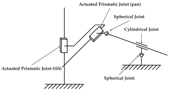
Figure 5.
Kinematic visualization of the proposed high-precision pointing mechanism. The two actuated prismatic joints comprise the XY-table, while the two spherical and the cylindrical joints make up the lever sub-system.
3.2. Actuation and Transmission Mechanism
The kinematic chain that actuates the final sensor mounting platform through the center shaft starts with two simple, commonly available rotary motors. The aim is to precisely control the position over the XY-Table. For this, a conversion from rotary motion to linear is required. An efficient way to achieve this is by using a linear spindle coupled with a ball screw bearing. This solution is widely used in the linear precision industry, for instance, amongst CNC machine makers, where it is generally required to have higher torques and smaller displacements. A spindle is fundamentally characterized by its pitch distance l, which is essentially the displacement of a ball screw after one spindle rotation. The rotation angle of the spindle and linear movement of the ball screw can consequently be linked using the cross-multiplication:
For precision mechanisms, ball screws can be pre-loaded to reduce clearances, backlash and improve accuracy. This is typically done by manufacturing the ball bearing slightly smaller than the balls themselves and press-fitting them into the case. The torque required for movements is increased through this process, but backlash can be reduced to virtually zero. Stabilizing and fixing the moving platform of the XY-Table is done using linear guides and linear polymer bearings for a low-cost but stable and low clearance mounting solution.
As previously described, the transmission mechanism consists of a double gimballed lever system. Placed after the XY-Table, the lever represents an essential system component. With the main task to convert linear motion back to rotary, this element also defines controllability, stability, and overall pointing speed. The lever’s length sets the balance between pointing precision and range of motion. By increasing this parameter, precision increases at the expense of decreasing pointing speed and increasing the frame size.
The central shaft is mounted using two universal joints, which act as gimbals to enable the rod’s pitch and yaw rotation. These joints are realized using 2 round concentric cases, mounted using orthogonally placed ball bearings, permitting the rotation around two axes. Similar pre-loading as described earlier is done through press-fitting to reduce backlashes. This is done equally for both universal joints (see Figure 6).
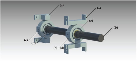
Figure 6.
Double-gimbal lever system for converting a translatory motion into a rotary one: (a) gimbal mounts; (b) central orienting shaft; (c) outer segment of universal joint for pan motion; (d) inner segment of universal joint for tilt motion; (e) circular joint in the form of a linear sliding bearing.
As one universal joint is static, while the other one moves within the actuation plane of the XY-Table, the distance between the two of them varies. A sliding joint is used to provide this extra degree of freedom required while enabling the shaft to freely move through the frontal universal joint. This is implemented using another linear polymer bearing to minimize clearances and backlash introduced into the system.
3.3. Actuator Selection
High-precision actuators can significantly add to a project’s cost, especially when factoring motor drivers, higher-level controllers, and communication interfaces. By using a completely integrated package, great results can be achieved at a low price point. After testing out some options, the system’s motor choice fell to the Dynamixel XL430-W250-T [161].
This motor consists of a completely integrated package, combining a Direct Current (DC)-motor, gearbox, driver, and encoder. Positioning, speed, and acceleration are controlled using a Proportional–Integral–Derivative (PID) closed-loop system that relies on a 4096 step encoder for feedback. Furthermore, the package includes a 258 to 1 reduction gearbox that is placed in-between the DC-motor and position encoder to identify and control any potential backlash.
Several package functions are based on an integrated microcontroller, which also enables a network interface to the outside to provide control commands via a half-duplex asynchronous serial connection. The final connection to a computer for the control interface is achieved using a custom-built Universal Serial Bus (USB) to half-duplex serial interface, which also integrates the power supply unit for the motors. The power supply consists of a simple commercially available buck converter, which reduces any DC input voltage to the required 12 V. Additionally, the manufacturer provides a Software Development Kit (SDK) to interface with the serial connection of the motors via the pre-defined protocol. This SDK is both available for Robot Operating System (ROS) [162], and Arduino to integrate further high-level real-time controls.
Significant characteristics of the selected actuator for the represented use case are stall torque and encoder resolution. The Dynamixel’s built-in 4096 / encoder provides the system with the needed resolution for this application. Furthermore, as precision mechanisms in general, and especially ours, use several press-fittings to reduce joint clearances and backlash, a non-negligible actuation force is required, even through the several reduction gears. The maximum of 1.5 Nm of stall torque can apply a sufficient force to also overcome static friction, even for small and slow movements. Further specifications of the selected actuator can be seen in Table 2.
Table 2.
Dynamixel XL430-W250-T specification according to the manufacturer. Of importance are especially the encoder resolution and the position control range, as well as a sufficient torque.
Using 3D-printed mounts, these motors are directly attached to the mechanism’s overall frame. Custom milled motor fixations attach the motor output directly to the corresponding ball screw without any further gears.
An alternative to using the fully integrated package would be a custom built solution. Significantly higher resolutions, torques, and speeds could be achieved as well using high-quality DC motors combined with harmonic drives [163], which exploit the deformation of gears to achieve high reduction rates and low backlash, as well as high-precision encoders [164]. Even individual components of such a setup will have significantly higher costs than the fully integrated package used for this research, and were therefore deemed over the price limit. A fully integrated motor setup using such high-quality components is the ANYdrive motor [165], but this was again above the target price point.
3.4. System Kinematics
A further in detail description of the kinematic transmission of movement from the integrated DC-motors to the final actuated sensor platform can be seen in Figure 7. According to this serial chain and by separating the individual axes of the mechanism, we can perform a simple analysis of the theoretical resolution and precision of the system, as well as its future movement control.
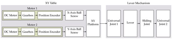
Figure 7.
Block diagram visualization of the kinematic chain of the proposed mechanism, highlighting mechanical components inside the servo motors as well as the two subsystems, the XY-Table as well as the lever mechanism.
Due to the integrated position encoders and the respective PID controllers, both motors can be interpreted as complete and independent subsystems. Their outputs are the respective rotary motor positions and . Using the ball screw lead, which is identical for both ball screws, the x and y positions of the XY-Table can be computed as
on which the first universal joint is placed. The conversion of this linear movement into a rotary pitch () and yaw () is performed by the lever in combination with those two universal joints, as shown in Figure 6. The system’s attitude can then be computed as
where (, ) are the center’s coordinates of the XY-Table, and D the separation of the two universal joints when the lever is not deflected at all. From this, the theoretical pointing resolution
based on the reported Dynamixel motor resolution = 0.08789/step, the ball screw lead l = 5 mm/rev and the lever length can be computed. This accuracy computation is an approximation, assuming the system operates close to its origin. As the system moves further away from the center point, out of the region of linear approximation of the arctan function, the resolution will increase, resulting in smaller and smaller angular step sizes in comparison to the respective motor steps.
The mathematical approximation of the gimbal model enables an understanding of the impact of design changes and component selection on the overall system performance. It can be observed that the pointing resolution is proportional to the motor resolution
The pointing resolution is proportional to the ball screw lead
In addition, the pointing resolution is inversely proportional to the separation of the rotation center to the XY-Table plane
By further analyzing this chain of mechanical components, we can derive a generic kinematic description of the system for classifying it according to its joint placement. The XY-Table consists of two prismatic joints in series, making it a PP-mechanism. The lever mechanism is held in place by two universal joints as well as a cylindrical one to enable the sliding motion. This constitutes a UCU-mechanism. As both parts are placed in series, this results in a PPUCU-mechanism. Some notations place a line above the actuated joints, making this a mechanism.
3.5. Clearance and Error Analysis
Even though our design provides a great down stepping of the original motor’s resolution, the kinematic chain in Figure 7 also highlights many joints and mechanical interactions, which introduce the possibilities of clearances, backlash, bending, and other possible sources of error. The following section highlights an analysis of possible weaknesses of the mechanisms and how much they could potentially impair the system’s precision. An overview is also given in Table 3. Furthermore, we demonstrate approaches that were taken to mitigate possible issues.
Table 3.
From the utilized components and overall system design, several sources of error can be identified and accounted for in the further steps of the system’s design.
3.5.1. Motors
The utilized Dynamixel motors come with an integrated gearbox. As stated in Section 2, georboxes are a frequent source of possible backlash. Some advantages of using the Dynamixel motors are, on the one hand, the precise industrial manufacturing, which already results in very low tolerances in the mechanism, and on the other hand, the backlash compensation happening while controlling the motor’s position due to the rotary encoder being placed at the end of the motor’s kinematic chain.
3.5.2. System Kinematics
The kinematics themselves do not result in a pure rotation, but there is also a falsely introduced translation of the sensor platform. Based on the system geometry shown in Figure 8, this can be calculated to be
using the gimbal to gimbal distance , based on the system’s deflection angles and :
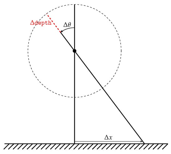
Figure 8.
Translation error introduced through rotation with a fixed-length shaft.
For the target application of LROD, this is not only a negligible deviation but also a predictable one and can therefore be disregarded for further development.
3.5.3. Ball Screws
Ball screws are an excellent option for precision mechanisms, as they can already come pre-loaded by their balls through the respective ball assembly [163]. The advantage of these is very low friction at high torque capabilities, which makes them a common, well-established, and affordable solution. The high-torque capability is especially beneficial due to the resistance created from the pre-loading of bearings within the various components. Sweeney et al. [151] also discusses the utility of ball screws in precision mechanisms, and how these can be utilized effectively.
Ball screws can introduce two possible kinds of play into the mechanism: axial and radial. In our case, radial play is immediately compensated through linear guides mounted parallel to the ball screws. Axial play, however, can affect the accuracy of the system and the manufacturer’s pre-loading of the ball assembly is therefore of high importance [166].
Unfortunately, as the utilized ball bearings were already available in our workshop, no manufacturer information is available about them. There does not seem to be any observable axial play, but the pressure exerted from linear guides on either side can also provide some pre-loading to reduce clearances, should there be any.
3.5.4. Linear Guides
According to the manufacturer’s specifications [167,168], there is a radial fitting tolerance of between the guide shaft and the respective shaft of the linear sliding bearing. A direction change of one axes could result in a backlash in the magnitude of the fitting tolerance, which cannot be ignored. Assuming all other variables remain constant, this could, according to Equation (6), result in a worst-case angular inaccuracy of
This is, however, compensated by several effects:
- Press-fitting the bearings into the respective structural part will result in a more optimal, tighter fit.
- As two linear guides are used in parallel with a very tight fit, both bearings will be pre-loaded thus reducing any possible play [169].
- In addition to the two linear bearings for each axis, there is also the ball screw, fixating the moving platform further and reducing possible backlash.
- By controlling the movement protocol of the XY table, it can be assured that all bearings are always on the same side of their clearances during a backlash and therefore compensating further for possible backlash.
3.5.5. Universal Joints/Gimbals/Ball Bearings
Ball bearings are utilized at various locations throughout the mechanism, especially inside the two universal joints that fixate the orienting lever. Axial play of the balls in these locations could dramatically affect the overall pointing precision of the device. During a simple direction change of motion, this clearance could cause a backlash in both universal joints, having double the effect on the pointing accuracy. Our design utilizes ball bearings by SKF featuring a axial play [170,171]. A deviation of 7 µm in both gimbals could lead according to Equation (6) to an error of
Again, several compensating effects are utilized:
- The most significant compensation action is the pre-loading of any bearing. This can be done in two ways: Simple press-fitting of the bearing onto the shaft and inside the casing will apply a significant force onto it and thus will permanently keep it at one side of the bearing’s clearance and reduce backlash [163].
- Spring-loading is a second method to reduce a bearing’s backlash but is not utilized in our design.
- Finally, again some backlash can be compensated for in the controls and calibration of the mechanism, though this can be unpredictable and might suffer in dynamic environments with high vibrations.
3.5.6. Frontal Linear Guide
The rotation center’s linear guide provides the extra degree of freedom for the system to transform the XY-Table translation into a rotation freely. The main shaft only moves inwards and does not conduct any rotary movement with respect to the linear bearing. The sleeve was purposely lengthened in this location to 20 mm to reduce the effect of any potential radial play. Low clearance and proper compatibility are especially ensured by having both the shaft and its sleeve manufactured by the same company. Furthermore, payload mass and gravity as a restoring force provide a degree of pre-loading onto the bearing, but further measures to reduce possible clearances could be applied in the future.
3.5.7. Bending Moments
The bending of the central shaft or other mounting components could introduce errors to the pointing accuracy. However, most components are milled out of aluminum and significantly over-dimensioned for the expected future payload. Furthermore, it is also assumed that should there be any significant bending effects; these should be constant in static measurement situations and would therefore only introduce a linear offset which can be compensated for in calibration.
3.5.8. Symmetry
Symmetric designs can compensate for many sources of errors like thermal expansion or bending in high-precision mechanisms [172]. As the linear stages, gimbals and chassis are fairly symmetric, the design benefits of symmetry error advantages. The book highlights the good practice of placing measurement axis in symmetry planes, balancing the effects of thermal expansion affecting either side of the symmetric plane equally. This practice has been adopted on many occasions throughout the design, specifically in the linear stages of the XY-Table and gimbals for the lever mechanism, but also the overall system frame.
3.6. Encoder and Position Feedback
In most common pan-tilt serial gimbal mechanisms, the encoder is placed at the rotational joint providing a direct measurement of the current orientation, enabling complete closed-loop control and the capability to adjust for any backlash or other errors. For high-precision measurements, this requires a very high-resolution position encoder, such as an EAM580-B [173]. However, even these expensive encoders only feature 14-bit single turn precision resulting in an angular step resolution of .
Our proposed mechanism utilizes the cheap AS5601 12-bit encoders [174] which are integrated into the motor package. As these are placed earlier in the mechanism in front of several down-stepping mechanisms, we can utilize the encoder over multiple motor turns, achieving a much higher step resolution, resulting in a final angular resolution of . The disadvantage of this placement is that the encoder is not at the end of the kinematic chain (as seen in Figure 7). This means that parts of the mechanism do not provide position feedback and therefore run in open-loop control. In the future application, this can be extended and improved using the sensors available in the to be mounted sensor platform, such as cameras and Inertial Measurement Unit (IMUs).
3.7. Control Systems
The general control systems of the developed pointing mechanism are integrated into the Dynamixel motor package. These motors interface with a control computer using a simple half-serial duplex communication. On the computer side, an interface is created using ROS [175] and the Dynamixel SDK. Transformation functions and the system kinematics can then be easily modeled in ROS to convert angular commands into the respective motor and encoder positions.
Low-level movement controls are handled by the integrated Cortex-M3 microcontroller, which handles position and velocity PID control to precisely steer the gimbal.
As the communication via USB with the computer and ROS and the sending of reactive commands is not a real-time operation, we have developed a second operation mode. In this case, an additional microcontroller in the form of an Arduino Zero [176] is placed in between the computer and the motors. The Arduino is now capable of collecting information from various sensors and sending real-time commands to the motors for precise control. Furthermore, by also running VersaVIS [177] on this microcontroller, the current gimbal positions can be precisely timestamped. High-level commands can still be sent from the computer via ROS and ROSserial [178] to the Arduino, which are processed and sent on to the motors. This allows, for example, the integration of optical limit switches [179], similar to ones found in 3D printers, which can be used for precise calibration of the gimbal parameters and motor encoders. Furthermore, in combination with IMUs, the Arduino could send commands for stabilization and disturbance suppression to the motor, which a computer could not provide in real-time.
4. Experimental Evaluation
To evaluate the pointing accuracy of the developed system, we performed a series of experiments in a controlled environment. In order to perform a direct and fair comparison to commercially available systems, we performed the same experiments using a consumer-level cinematography gimbal.
4.1. Experimental Setup
4.1.1. Environment
The experiments were performed in a controlled lab environment to ensure the highest possible accuracy. The pointing device was placed at one end of a long and empty corridor, with target points placed at the opposite end. To observe the precise movements of the orienting mechanism, a laser diode was mounted in place of the future sensor setup to highlight the targeted position at the end of the measuring range. Individual measurement points of the laser diode were recorded on graph paper located at the opposite end of the corridor. To minimize distortions, the paper was mounted to a flat board that was secured to the wall. The measuring distance between the target area and the pointing mechanism was measured using a Leica Disto D8, a separate construction grade laser distance meter with an accuracy of [180]. It was measured from the center of rotation in the frontal gimbal of the pointing platform to the graph paper sheet and determined to be .
The system was securely mounted to a table using clamps, and all moving parts and cables were securely fixed to the table to prevent any disturbances. The control computer from which an operator can send position commands was placed on a separate table to minimize the interactions with the system.
4.1.2. System Setup
The mechatronic components of the pointing mechanism were controlled from a separate computer via a self-developed control board. On the software side, the servos are controlled using the Dynamixel SDK, provided by the manufacturer, as well as a custom ROS node, to send commands according to the specified experiment protocol. The low-level position control of the gimbal is performed by the Dynamixel internal micro-controller using a PID controller. The values for which were chosen to be: , , .
The visualization of the targeted position is done using a laser diode. This is mounted instead of the sensor platform using a 3D-printed fixture. The utilized diode is a Picotronic DA650-1-5(11X60) [181] and has a focal length of , with a beam diameter of and a beam divergence of . It is possible to visually determine a center of the projected laser point, but ultimately this places a lower limit on the evaluation accuracy of this experiment.
4.1.3. Calibration
The pointing mechanism has a few mechanical parameters which are originally undetermined and can be obtained through a calibration procedure from a set of measurement points. The most significant parameter is the principal point of the mechanism. As the motor encoders set their origin at an arbitrary location, it is necessary to determine the encoder position of the pointing origin when no deflection takes place. As the lever motion does not linearly transform encoder steps into angular steps, this is especially significant. This means that the pointing resolution at the principal point is the lowest (the worst) and increases (improves) towards the edges. This nonlinearity can be used in combination with a set of measurements to determine the principal point relative to the origin of the motor encoders.
Further system calibration parameters stem from various manufacturing inaccuracies. It can be observed, that the axes of the XY-Table are not perfectly perpendicular, but slightly skewed. This defect can be determined through calibration and, therefore, can be compensated for in the experimental setup. A deviation of 0.175 deg has been observed.
4.1.4. Experimental Protocol
The limited space of the long corridor does not permit a high-accuracy evaluation of the system’s full range of motion. The first step of the experiment was, therefore, to determine the maximally available range of motion, which will still result in all projected laser points lying within the target area. This range of motion was determined to be in pan and in tilt. To prevent a human bias in the selection of target points, these were sampled uniformly within the previously determined range.
Furthermore, a control strategy has been implemented to minimize backlash and bending effects. This strategy can shortly be summarized as:
- Input of new target position.
- Orienting mechanism is actuated along the tilt axis to 500 encoder steps on top of the desired target tilt coordinate.
- Orienting mechanism is actuated along the tilt axis to the desired target tilt coordinate.
- Orienting mechanism is actuated along the pan axis to 500 encoder steps on left of the desired target pan coordinate.
- Orienting mechanism is actuated along the pan axis to the desired target pan coordinate.
This strategy ensures that target points are always approached from the same direction (top-left), ensuring that backlash and bending effects always influence the result in the same way and can therefore be controlled.
Before the beginning of the experiment, the PID values of the integrated motor controllers were tuned manually. Convergence speed was not a priority during this experiment, so these values were chosen in order to ensure convergence with minimal overshoot.
The overall experiment protocol for recording data points was therefore:
- Generate a new random target position.
- Actuate the orienting mechanism to the given target position according to the previously defined control strategy.
- On the controller side, the commanded target position is recorded, as well as the continuously reported pointing position as the mechanism acts upon the command. Additionally, the final convergence point is recorded. For later data association, each target position is assigned an ID, which is also assigned to all associated recordings.
- The projected target point on the graph paper is manually recorded with the respective target ID.
At the end of the experiment, the data points are manually read off from the graph paper and added to the digital recording of the controller commands and values. This manual process also limits the evaluation accuracy, as points could only be read off to an approximate accuracy of .
4.2. Results
From the previously described experiment, a total number of 182 corresponding measurement points could be obtained. These lie in a measuring range of along the pan axis and along the tilt axis. Two measurements have been removed, as they were out of the range of the manual recording process. One measurement has been removed, as it is presumed to be a manual measurement error, due to its significant misalignment, resulting in a total of 179 measurement points. The subsequent sections will analyze this data regarding the overall pointing error, and try to recognize individual sources of error within the mechanism. Manual measurement points on the graph paper have been converted to degrees based on the distance measurement to the wall of . Recorded encoder position values have been converted to the corresponding gimbal attitude in degrees based on the previously described system kinematics and a system calibration obtained from a subset of the measurement points. The final measurement points have been aligned with the target points to remove any linear offsets in the mechanism or the experimental setup using least-squares optimization. This would also be part of a complete calibration procedure.
4.2.1. Overall Pointing Error
A first evaluation can be done by comparing the commanded position values to those observed in the experiment. This can be observed in Figure 9 by comparing commanded (blue) and measured (red) point positions. This can be observed to be an Root Mean Square Error (RMSE) of 6.203 mdeg, as well as a maximum error of 18.824 mdeg. Due to the motor’s internal PID-controller, the commanded position is, however, not always identical to the reached position of the motor and therefore the actual gimbal attitude. However, this error is observable through the motor encoders and therefore enables a second evaluation of the gimbal attitude reported by the encoders to the measured values. This RMSE is determined to be 6.179 mdeg with a maximum error of 18.854 mdeg, which is also shown in Table 4. In addition, 83.8% of measuring points were therefore within the required accuracy range of 7.5 mdeg.
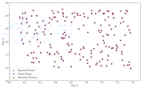
Figure 9.
Representation of commanded (blue) and reported (green) to measured (red) pointing position. Due to good motor controls, the reported position is nearly always covered by the commanded position.
Table 4.
This table highlights the individual pointing errors of each axis as well as the overall pointing error. Both the RMSE () and the maximum pointing error () are shown.
In all further evaluations, the reported value of the motor encoders will be used to determine the relevant gimbal attitude, as this value is not subject to PID-controller tuning or other control mechanisms.
A histogram plot visualizing the distribution of pointing errors can be seen in Figure 10a. This graph also highlights that the majority of all measurement points lie within the required pointing accuracy. The spread of pointing errors throughout the measuring range is visualized using a heatmap in Figure 10b, showing regions of larger or lower error.
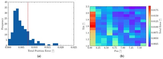
Figure 10.
(a,b) visualize the system’s overall pointing error and its distribution. (a) Histrogram highlighting the distribution of RMSE pointing errors. The red line highlights our overall accuracy requirement (b) Heatmap visualization of pointing errors. Large red-spot due to one large mis-aligned measurement and no further points in that area.
4.2.2. Evaluating Axis Performance
The pan and tilt axis of the mechanism can be regarded as separate from each other, as one does not influence the other and should therefore both be evaluated individually. Figure 11 visualizes the mis-projection of each individual measurement point. The minimum required pointing accuracy is highlighted using the red circle and shows that the majority of measurement points fulfill this requirement.
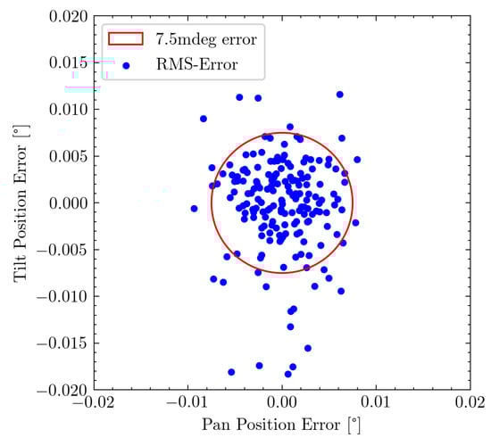
Figure 11.
Relative RMSE of each individual measurement point. The red circle shows our requirement accuracy of 7.5 mdeg.
Figure 12a shows the distribution of orienting errors along each axis. A slightly wider error distribution can be observed for the tilt axis. This is also represented in the RMSE values, where along the pan axis an error of 2.801 mdeg with a maximum of 9.355 mdeg is achieved, while along the tilt axis a RMSE of 3.671 mdeg with a maximum of 18.278 mdeg is observable.
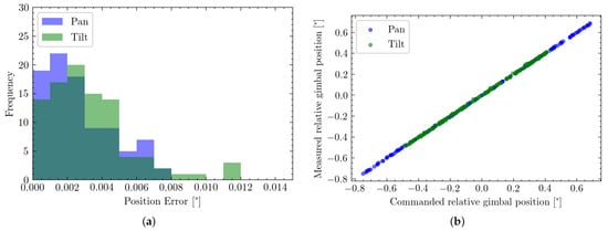
Figure 12.
Evaluating error distribution and system linearity for both the pan (blue) and tilt (green) axis. (a) Histogram of error distribution along the individual axis; (b) Linearity of commanded position to the measured output.
Furthermore, by separating the data into individual axes, a slight skew in the mechanism is observable. This is due to a misalignment of the pan and tilt axis during assembly. A rotation of 0.175 deg of the tilt axis relative to the pan one can be determined. However, this can be compensated for in calibration and has already been included in the previously stated system calibration.
4.2.3. Observing Linearity of Command and Measure Points
An essential factor, especially for later control systems, is the system’s linearity. How well do measured position and target position coincide? This is shown in Figure 12b. From both visualizations, it can be seen that the system expressed a very linear behavior. This can also be quantified by computing the correlation of each set, resulting in a value of for the pan axis, as well as for the tile axis.
4.2.4. Error Source Analysis
Certain types of induced errors can be proportional to the distance travelled, the distance between two consecutive measurement points, of the mechanism. This can for example be friction or bending effects in the mechanism, which accumulate during the motion from one measurement point to the next.
This correlation would not have to be linear, but neither Figure 13 nor the logarithmic version revealed any distinguishable correlation.
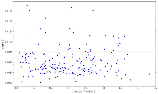
Figure 13.
Comparison of distance travelled between two consecutive measurement points to the respective RMSE of the following measurement point.
This can mostly be accredited to the employed control methods and movement protocols, described in Section 4.1.4, which specifically aimed at reducing such errors.
4.2.5. Commercial Gimbal Comparison
To perform a direct comparison to commercially available solutions in the same price segment, we repeated the same experiment using a DJI RS2 cinematography gimbal. The measurement range was determined to be 46.12 m, but due to the very limited resolution of the gimbal of only 0.1 deg, only very few measurement points could be obtained. In total, 107 points were recorded.
A similar RMSE visualiszation has been created in Figure 14 and the RMSE has been calculated to be 30.93 mdeg.
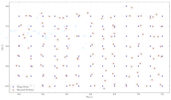
Figure 14.
RMSE evaluation of the DJI RS2.
This error is significantly higher than what would be usable for our target application, but even more, the very limited actuation resolution makes this an unsuitable solution to our problem.
4.3. Discussion
From the reported experimental results, several observations and conclusions can be drawn regarding the system’s precision:
- The observed pointing precision is as close as possible to the evaluation precision of the experimental setup. Over the available measurement range, even deviations of single millimeters cause errors in the range of millidegrees. Therefore, the evaluation accuracy is limited by the laser-pointer’s accuracy, the marking of the experimenter, and the later digitalization of the paper markings.Furthermore, the recording graph paper, which was taped to a pinboard fixed on a wall, is a possible source of error by itself.Effectively, bending of the data recording paper might have caused the measurement distortion seen in the left part of Figure 10b. It is, therefore, hard to conclude with the available measuring equipment, whether the actual pointing accuracy is equal to the observed one or if the system is even more precise but can not be evaluated at the better precision.
- A second observable source of error comes from the linear bearing within the frontal gimbal, responsible for the free movement of the orienting shaft. This bearing has been damaged slightly during assembly, resulting in minimal play. Fortunately, performance is not significantly impacted statically due to the effect of gravity and the large diameter of both the shaft and bearing; nevertheless, the part would need to be replaced for more dynamic scenarios.
- Nonlinear bending effects in 3D printed components like the motor mounts could still impact performance. This could be evaluated using a Finite Element Method (FEM) simulation and their design could be further optimized, for example using generative design methods. Furthermore, adequate control methods could be used to compensate for these effects [182].
- As the calibration of the mechanism’s intrinsic parameters, especially the principal point, is currently done using external experiment data; these are also subject to the same experimental inaccuracies. We are therefore planning to expand the system’s controls using optical limit switches (such as ones found in CNC machines and 3D printers), to perform an automatic self-calibration.
- Furthermore, it can be observed that significantly more projection errors are observable in the tilt axis than the pan axis. This could be caused by the staging in the XY-Table, as the tilt axis has to carry more loads and might be subject to more vibrations from the series of actuators. For our future target application of Long-Range Obstacle Detection, this is not problematic, as the pan axis is more critical for covering the vehicle’s FoV.
- Oscillations during the convergence to a new measurement point due to the motor’s internal PID controls are also a possible source of inaccuracies. These can be reduced using further and more extensive tuning of the PID parameters.
5. Cost Analysis
One of the main goals of this project was to develop a low-cost system. The total cost of the utilized components was $1000 and is broken down in Table 5. Where components were manufactured using available in-house machinery, such as 3D printers and CNC machines, only material costs are listed.
Table 5.
Project cost analysis including purchased components and materials. As manufacturing took place in-house, this is not listed here. Some components were already available in the workshop and their original price is not known; the respective costs were estimated.
The manufacturing cost for a comparable system using a classical serial pan/tilt design, which employs high-precision components, such as harmonic gearboxes, precision motors, encoders, and additional materials, was estimated to amount to approximately $2500.
6. Conclusions
In this paper, we demonstrated a high-precision pointing mechanism for future utilization in a railway Long-Range Obstacle Detection. Due to the low target price point, the system consists of simple and widely available low-cost components as well as in-house manufactured parts. By creating a novel actuation mechanism consisting of a common XY-Table and a double-hinged lever system, a very small rotation resolution was achieved. Various means of pre-loading can keep clearances in the mechanism, and therefore backlash to a minimum, resulting in very high-precision and high accuracy in the device’s pointing performance. We validated our design using a controlled indoor experiment, during which we recorded measurements over a range of nearly 50 m. Our experiment has shown that our system is capable of precisely and accurately targeting individual points at a long range, with an angular resolution comparable to that required for detecting humans at 1500 m using a long-range LiDAR. The achieved pointing precision reached what was possible to evaluate using our available experimental procedure, and highlighted the challenges of testing and calibrating high-precision equipment. For the future target application of LROD, this provides sufficient pointing precision to target and track long-range obstacles reliably. The high pan position accuracy makes this mechanism particularly suitable to explore the train’s FoV. Nevertheless, the impact of vibrations and disturbances from train operations will have to be investigated further in the future.
We plan to continue the development of this mechanism, specifically in the realm of controls, to be able to achieve high-pointing precision under dynamic scenarios, remove possible nonlinear errors from bending or backlash effects, and integrate a self-calibration procedure. Furthermore, we aim to combine this with a suitable long-range sensor setup, consisting of a 1D-LiDAR and several cameras to construct a complete Long-Range Obstacle Detection system.
Author Contributions
Conceptualization: E.H.A., F.T. and R.S.; Data curation: C.v.E.; Formal analysis: C.v.E. and E.H.A.; Design: E.H.A.; Prototyping: E.H.A.; Funding acquisition: F.T., C.C. and R.S.; Investigation: E.H.A., C.v.E. and F.T.; Methodology: E.H.A., C.v.E. and F.T.; Project Administration: F.T., C.C. and R.S.; Resources: C.C. and R.S.; Software: C.v.E.; Supervision: F.T. and C.C.; Validation: E.H.A. and C.v.E.; Visualization: C.v.E.; Writing—original draft: C.v.E.; Writing—review and editing: C.v.E., F.T., C.C. and E.H.A. All authors have read and agreed to the published version of the manuscript.
Funding
This research was funded by the ETH Mobility Initiative under the project LROD.
Institutional Review Board Statement
Not applicable.
Informed Consent Statement
Not applicable.
Data Availability Statement
The data presented in this study are openly available and can be found here: https://projects.asl.ethz.ch/datasets/doku.php?id=high_precision_gimbal (accessed on 31 December 2021).
Acknowledgments
The authors would like to thank Markus Bühler for manufacturing custom aluminium components and the members of the LROD project for their valuable inputs.
Conflicts of Interest
The authors declare no conflict of interest. The funders had no role in the design of the study; in the collection, analyses, or interpretation of data; in the writing of the manuscript, or in the decision to publish the results.
Abbreviations
The following abbreviations are used in this manuscript:
| IMU | Inertial Measurement Unit |
| DoF | Degrees of Freedom |
| FoV | Field of View |
| RMSE | Root Mean Square Error |
| LiDAR | Light Detection and Ranging |
| MEMS | Micro-Electromechanical Systems |
| ETCS | European Train Control System |
| RoI | Region of Interest |
| LROD | Long-Range Obstacle Detection |
| CAD | Computer-Aided Design |
| CNC | Computer Numerical Control |
| USB | Universal Serial Bus |
| SDK | Software Development Kit |
| DC | Direct Current |
| ROS | Robot Operating System |
| PID | Proportional–Integral–Derivative |
| FEM | Finite Element Method |
| RGB | Red, Green and Blue |
References
- Stanley, P. ETCS for Engineers, 1st ed.; TZ-Verl. & Print Gmbh: Roßdorf, Germany, 2011. [Google Scholar]
- Barney, D.; Haley, D.; Nikandros, G. Calculating Train Braking Distance. In Conferences in Research and Practice in Information Technology Series; Australian Computer Society: Darlinghurst, Australia, 2001; Volume 146, p. 7. [Google Scholar] [CrossRef]
- Ristić-Durrant, D.; Franke, M.; Michels, K. A Review of Vision-Based On-Board Obstacle Detection and Distance Estimation in Railways. Sensors 2021, 21, 3452. [Google Scholar] [CrossRef]
- Fel, L.; Zinner, C.; Kadiofsky, T.; Pointner, W.; Weichselbaum, J.; Reisner, C. ODAS—An Anti-Collision Assistance System for Light Rail Vehicles and Further Development. In Proceedings of the 7th Transport Research Arena TRA, Vienna, Austria, 16–19 April 2018; Zenodo: Vienna, Austria, 2018. [Google Scholar] [CrossRef]
- Poulton, C.V.; Byrd, M.J.; Russo, P.; Timurdogan, E.; Khandaker, M.; Vermeulen, D.; Watts, M.R. Long-Range LiDAR and Free-Space Data Communication With High-Performance Optical Phased Arrays. IEEE J. Sel. Top. Quantum Electron. 2019, 25, 1–8. [Google Scholar] [CrossRef]
- Kroemer Elbert, K.E.; Kroemer, H.B.; Kroemer Hoffman, A.D. Size and Mobility of the Human Body. In Ergonomics; Elsevier: Amsterdam, The Netherlands, 2018; pp. 3–44. [Google Scholar] [CrossRef]
- He, D.; Zou, Z.; Chen, Y.; Liu, B.; Yao, X.; Shan, S. Obstacle Detection of Rail Transit Based on Deep Learning. Measurement 2021, 176, 109241. [Google Scholar] [CrossRef]
- Kapoor, R.; Goel, R.; Sharma, A. Deep Learning Based Object and Railway Track Recognition Using Train Mounted Thermal Imaging System. J. Comput. Theor. Nanosci. 2020, 17, 5062–5071. [Google Scholar] [CrossRef]
- Mukojima, H.; Deguchi, D.; Kawanishi, Y.; Ide, I.; Murase, H.; Ukai, M.; Nagamine, N.; Nakasone, R. Moving Camera Background-Subtraction for Obstacle Detection on Railway Tracks. In Proceedings of the 2016 IEEE International Conference on Image Processing (ICIP), Phoenix, AZ, USA, 25–28 September 2016; IEEE: Piscataway, NJ, USA, 2016; pp. 3967–3971. [Google Scholar] [CrossRef]
- Uribe, J.A.; Fonseca, L.; Vargas, J.F. Video Based System for Railroad Collision Warning. In Proceedings of the 2012 IEEE International Carnahan Conference on Security Technology (ICCST), Newton, MA, USA, 15–18 October 2012; IEEE: Piscataway, NJ, USA, 2012; pp. 280–285. [Google Scholar] [CrossRef]
- Nassu, B.T.; Ukai, M. Automatic Recognition of Railway Signs Using SIFT Features. In Proceedings of the 2010 IEEE Intelligent Vehicles Symposium, La Jolla, CA, USA, 21–24 June 2020; IEEE: Piscataway, NJ, USA, 2010; pp. 348–354. [Google Scholar] [CrossRef]
- Manikandan, R.; Balasubramanian, M.; Palanivel, S. Vision based obstacle detection on railway track. Int. J. Pure Appl. Math. 2017, 116, 567–576. [Google Scholar]
- Wang, Z.; Wu, X.; Yu, G.; Li, M. Efficient Rail Area Detection Using Convolutional Neural Network. IEEE Access 2018, 6, 77656–77664. [Google Scholar] [CrossRef]
- Nakasone, R.; Nagamine, N.; Ukai, M.; Mukojima, H.; Deguchi, D.; Murase, H. Frontal Obstacle Detection Using Background Subtraction and Frame Registration. Q. Rep. RTRI 2017, 58, 298–302. [Google Scholar] [CrossRef]
- Saika, S.; Takahashi, S.; Takeuchi, M.; Katto, J. Accuracy Improvement in Human Detection Using HOG Features on Train-Mounted Camera. In Proceedings of the 2016 IEEE 5th Global Conference on Consumer Electronics, Kyoto, Japan, 11–14 October 2016; IEEE: Piscataway, NJ, USA, 2016; pp. 1–2. [Google Scholar] [CrossRef]
- Ye, T.; Wang, B.; Song, P.; Li, J. Automatic Railway Traffic Object Detection System Using Feature Fusion Refine Neural Network under Shunting Mode. Sensors 2018, 18, 1916. [Google Scholar] [CrossRef]
- Fonseca Rodriguez, L.A.; Uribe, J.A.; Vargas Bonilla, J.F. Obstacle Detection over Rails Using Hough Transform. In Proceedings of the 2012 XVII Symposium of Image, Signal Processing, and Artificial Vision (STSIVA), Medellin, Antioquia, Colombia, 2–14 September 2012; IEEE: Piscataway, NJ, USA, 2012; pp. 317–322. [Google Scholar] [CrossRef]
- Yu, M.; Yang, P.; Wei, S. Railway Obstacle Detection Algorithm Using Neural Network. AIP Conf. Proc. 2018, 1967, 040017. [Google Scholar] [CrossRef]
- Ye, T.; Zhang, X.; Zhang, Y.; Liu, J. Railway Traffic Object Detection Using Differential Feature Fusion Convolution Neural Network. IEEE Trans. Intell. Transp. Syst. 2021, 22, 1375–1387. [Google Scholar] [CrossRef]
- Xu, Y.; Gao, C.; Yuan, L.; Tang, S.; Wei, G. Real-Time Obstacle Detection Over Rails Using Deep Convolutional Neural Network. In Proceedings of the 2019 IEEE Intelligent Transportation Systems Conference (ITSC), Auckland, New Zealand, 27–30 October 2019; IEEE: Piscataway, NJ, USA, 2019; pp. 1007–1012. [Google Scholar] [CrossRef]
- Li, J.; Zhou, F.; Ye, T. Real-World Railway Traffic Detection Based on Faster Better Network. IEEE Access 2018, 6, 68730–68739. [Google Scholar] [CrossRef]
- RailVision.IO. Technical Report, RailVision.IO. 2021. Available online: https://railvision.io (accessed on 31 December 2021).
- RailwayPro. Obstacle Detection Systems for SBB Cargo Shunting Locomotives. Article, RailwayPro. 2020. Available online: https://www.railwaypro.com/wp/obstacle-detection-systems-for-sbb-cargo-shunting-locomotives/ (accessed on 31 December 2021).
- Ristić-Durrant, D.; Haseeb, M.A.; Franke, M.; Banić, M.; Simonović, M.; Stamenković, D. Artificial Intelligence for Obstacle Detection in Railways: Project SMART and Beyond. In Dependable Computing—EDCC 2020 Workshops; Bernardi, S., Vittorini, V., Flammini, F., Nardone, R., Marrone, S., Adler, R., Schneider, D., Schleiß, P., Nostro, N., Løvenstein Olsen, R., et al., Eds.; Springer International Publishing: Cham, Switzerland, 2020; Volume 1279, pp. 44–55. [Google Scholar] [CrossRef]
- Kudinov, I.A.; Kholopov, I.S. Perspective-2-Point Solution in the Problem of Indirectly Measuring the Distance to a Wagon. In Proceedings of the 2020 9th Mediterranean Conference on Embedded Computing (MECO), Budva, Montenegro, 8–11 June 2020; IEEE: Piscataway, NJ, USA, 2020; pp. 1–5. [Google Scholar] [CrossRef]
- Fioretti, F.; Ruffaldi, E.; Avizzano, C.A. A Single Camera Inspection System to Detect and Localize Obstacles on Railways Based on Manifold Kalman Filtering. In Proceedings of the 2018 IEEE 23rd International Conference on Emerging Technologies and Factory Automation (ETFA), Turin, Italy, 4–7 September 2018; IEEE: Piscataway, NJ, USA, 2018; pp. 768–775. [Google Scholar] [CrossRef]
- Weichselbaum, J.; Zinner, C.; Gebauer, O.; Pree, W. Accurate 3D-Vision-Based Obstacle Detection for an Autonomous Train. Comput. Ind. 2013, 64, 1209–1220. [Google Scholar] [CrossRef]
- Zhou, X.; Guo, B.; Wei, W. Railway Clearance Intrusion Detection Method with Binocular Stereo Vision. In Young Scientists Forum 2017; Zhuang, S., Chu, J., Pan, J.W., Eds.; SPIE: Shanghai, China, 2018; p. 45. [Google Scholar] [CrossRef]
- Chernov, A.; Butakova, M.; Guda, A.; Shevchuk, P. Development of Intelligent Obstacle Detection System on Railway Tracks for Yard Locomotives Using CNN. In Dependable Computing—EDCC 2020 Workshops; Bernardi, S., Vittorini, V., Flammini, F., Nardone, R., Marrone, S., Adler, R., Schneider, D., Schleiß, P., Nostro, N., Løvenstein Olsen, R., Eds.; Springer International Publishing: Cham, Switzerland, 2020; Volume 1279, pp. 33–43. [Google Scholar] [CrossRef]
- Ukai, M. A New System for Detecting Obstacles in Front of a Train. Railw. Technol. Avalance 2006, 12, 73. [Google Scholar]
- Ukai, M.; Nassu, B.T.; Nagamine, N.; Watanabe, M.; Inaba, T. Obstacle Detection on Railway Track by Fusing Radar and Image Sensor. In Proceedings of the 9th World Congress on Railway Research (WCRR), Paris, France, 22–26 May 2011; p. 12. [Google Scholar]
- Nassu, B.T.; Ukai, M. A Vision-Based Approach for Rail Extraction and Its Application in a Camera Pan–Tilt Control System. IEEE Trans. Intell. Transp. Syst. 2012, 13, 1763–1771. [Google Scholar] [CrossRef]
- Ruder, M.; Mohler, N.; Ahmed, F. An Obstacle Detection System for Automated Trains. In Proceedings of the IEEE IV2003 Intelligent Vehicles Symposium, Columbus, OH, USA, 9–11 June 2003; IEEE: Piscataway, NJ, USA, 2003; pp. 180–185. [Google Scholar] [CrossRef]
- Pavlović, M.; Ćirić, I.; Nikolić, V.; Simonović, M.; Stevanović, J. Thermal image processing for autonomous train operation obstacle detection system. In Proceedings of the XXVII MNTK “ADP-2018”, Sozopol, Bulgaria, 13–15 September 2018; pp. 324–328. [Google Scholar]
- Pavlovic, M.; Ciric, I.; Ristic-Durrant, D.; Nikolic, V.; Simonovic, M.; Ciric, M.; Banic, M. Advanced Thermal Camera Based System for Object Detection on Rail Tracks. Therm. Sci. 2018, 22, 1551–1561. [Google Scholar] [CrossRef]
- Haseeb, M.A.; Ristić-Durrant, D.; Gräser, A. Long-Range Obstacle Detection from a Monocular Camera. In Proceedings of the ACM Computer Science in Cars Symposium (CSCS), Munich, Germany, 6 July 2018; p. 3. [Google Scholar]
- Ristić-Durrant, D.; Haseeb, M.A.; Emami, D.; Gräser, A. Multimodal Sensor Fusion for Reliable Detection of Obstacles on Railway Tracks. J. Mechatron. Autom. Identif. Technol. 2018, 3, 7. [Google Scholar]
- Ristić-Durrant, D.; Haseeb, M.A.; Banić, M.; Stamenković, D.; Simonović, M.; Nikolić, D. SMART On-Board Multi-Sensor Obstacle Detection System for Improvement of Rail Transport Safety. Proc. Inst. Mech. Eng. Part F J. Rail Rapid Transit 2021, 2021, 095440972110327. [Google Scholar] [CrossRef]
- Ristić-Durrant, D.; Haseeb, M.A.; Banić, M.; Stamenković, D.; Simonović, M.; Miltenović, A.; Nikolić, V.; Nikolić, D. Obstacle detection for railways: Lessons learned from project smart. In Proceedings of the XIX International Scientific-Expert Conference on Railways—RAILCON 2020, Niš, Serbia, 15–16 October 2020; p. 9. [Google Scholar]
- Ristić-Durrant, D.; Ćirić, I.; Simonović, M.; Nikolić, V.; Leu, A.; Brindić, B. Towards autonomous obstacle detection in freight railway. In Proceedings of the XVII International Scientific-Expert Conference on Railways, Toronto, ON, Canada, 17–22 July 2016; p. 8. [Google Scholar]
- Zhangyu, W.; Guizhen, Y.; Xinkai, W.; Haoran, L.; Da, L. A Camera and LiDAR Data Fusion Method for Railway Object Detection. IEEE Sens. J. 2021, 21, 13442–13454. [Google Scholar] [CrossRef]
- Mockel, S.; Scherer, F.; Schuster, P. Multi-Sensor Obstacle Detection on Railway Tracks. In Proceedings of the IEEE IV2003 Intelligent Vehicles Symposium, Columbus, OH, USA, 9–11 June 2003; IEEE: Piscataway, NJ, USA, 2003; pp. 42–46. [Google Scholar] [CrossRef]
- Yokoyama, H.; Date, H.; Kanai, S.; Takeda, H. Detection and Classification of Pole-like Objects from Mobile Laser Scanning Data of Urban Environments. Int. J. CAD/CAM 2013, 13, 10. [Google Scholar]
- Karaduman, M. Image Processing Based Obstacle Detection with Laser Measurement in Railways. In Proceedings of the 2017 10th International Conference on Electrical and Electronics Engineering (ELECO), Bursa, Turkey, 30 November–2 December 2017; p. 5. [Google Scholar]
- Yamashita, H.; Iida, Y.; Nakamoto, J.; Koyama, Y.; Sato, M. Development of Railway Obstacle Detection System; Technical Report; Mitsubishi Heavy Industries: Tokyo, Japan, 1996. [Google Scholar]
- Tan, W.; Yan, B.; Bare, B. Feature Super-Resolution: Make Machine See More Clearly. In Proceedings of the IEEE Conference on Computer Vision and Pattern Recognition (CVPR), Salt Lake City, UT, USA, 18–23 June 2018; p. 9. [Google Scholar]
- Ren, Y.; Zhu, C.; Xiao, S. Small Object Detection in Optical Remote Sensing Images via Modified Faster R-CNN. Appl. Sci. 2018, 8, 813. [Google Scholar] [CrossRef]
- Li, Y.; Shi, T.; Zhang, Y.; Chen, W.; Wang, Z.; Li, H. Learning Deep Semantic Segmentation Network under Multiple Weakly-Supervised Constraints for Cross-Domain Remote Sensing Image Semantic Segmentation. ISPRS J. Photogramm. Remote Sens. 2021, 175, 20–33. [Google Scholar] [CrossRef]
- Yang, X.; Wu, W.; Liu, K.; Kim, P.W.; Sangaiah, A.K.; Jeon, G. Long-Distance Object Recognition With Image Super Resolution: A Comparative Study. IEEE Access 2018, 6, 13429–13438. [Google Scholar] [CrossRef]
- Li, K.; Wan, G.; Cheng, G.; Meng, L.; Han, J. Object Detection in Optical Remote Sensing Images: A Survey and a New Benchmark. ISPRS J. Photogramm. Remote Sens. 2020, 159, 296–307. [Google Scholar] [CrossRef]
- James, J.; Ford, J.J.; Molloy, T.L. Learning to Detect Aircraft for Long-Range Vision-Based Sense-and-Avoid Systems. IEEE Robot. Autom. Lett. 2018, 3, 4383–4390. [Google Scholar] [CrossRef]
- van den Hoogen, B.; Uijens, W.; den Hollander, R.J.M.; Huizinga, W.; Dijk, J.; Schutte, K. Long-Range Person and Vehicle Detection. In Artificial Intelligence and Machine Learning in Defense Applications II; Dijk, J., Ed.; SPIE: London, UK, 2020; p. 24. [Google Scholar] [CrossRef]
- Williamson, T.; Thorpe, C. A Trinocular Stereo System for Highway Obstacle Detection. In Proceedings of the 1999 IEEE International Conference on Robotics and Automation (Cat. No. 99CH36288C), Detroit, MI, USA, 10–15 May 1999; IEEE: Piscataway, NJ, USA, 1999; Volume 3, pp. 2267–2273. [Google Scholar] [CrossRef]
- Pinggera, P.; Franke, U.; Mester, R. High-Performance Long Range Obstacle Detection Using Stereo Vision. In Proceedings of the 2015 IEEE/RSJ International Conference on Intelligent Robots and Systems (IROS), Hamburg, Germany, 28 September–3 October 2015; IEEE: Piscataway, NJ, USA, 2015; pp. 1308–1313. [Google Scholar] [CrossRef]
- Wang, H.; Mou, X.; Mou, W.; Yuan, S.; Ulun, S.; Yang, S.; Shin, B.S. Vision Based Long Range Object Detection and Tracking for Unmanned Surface Vehicle. In Proceedings of the 2015 IEEE 7th International Conference on Cybernetics and Intelligent Systems (CIS) and IEEE Conference on Robotics, Automation and Mechatronics (RAM), Siem Reap, Cambodia, 15–17 July 2015; IEEE: Piscataway, NJ, USA, 2015; pp. 101–105. [Google Scholar] [CrossRef]
- Zhang, K.; Xie, J.; Snavely, N.; Chen, Q. Depth Sensing Beyond LiDAR Range. In Proceedings of the 2020 IEEE/CVF Conference on Computer Vision and Pattern Recognition (CVPR), Seattle, WA, USA, 13–19 June 2020; IEEE: Piscataway, NJ, USA, 2020; pp. 1689–1697. [Google Scholar] [CrossRef]
- Dickmanns, E.D. An Advanced Vision System For Ground Vehicles. In Proceedings of the 1st International Workshop on In-Vehicle Cognitive Computer Vision Systems (IVCCVS), Graz, Austria, 3 April 2003; p. 12. [Google Scholar]
- Kendall, A.; Martirosyan, H.; Dasgupta, S.; Henry, P.; Kennedy, R.; Bachrach, A.; Bry, A. End-to-End Learning of Geometry and Context for Deep Stereo Regression. arXiv 2017, arXiv:1703.04309. [Google Scholar]
- Tonioni, A.; Tosi, F.; Poggi, M.; Mattoccia, S.; Di Stefano, L. Real-Time Self-Adaptive Deep Stereo. arXiv 2019, arXiv:1810.05424. [Google Scholar]
- Yang, G.; Zhao, H.; Shi, J.; Deng, Z.; Jia, J. SegStereo: Exploiting Semantic Information for Disparity Estimation. arXiv 2018, arXiv:1807.11699. [Google Scholar]
- Perrollaz, M.; Labayrade, R.; Royere, C.; Hautiere, N.; Aubert, D. Long Range Obstacle Detection Using Laser Scanner and Stereovision. In Proceedings of the 2006 IEEE Intelligent Vehicles Symposium, Meguro-Ku, Japan, 13–15 June 2006; IEEE: Piscataway, NJ, USA, 2006; pp. 182–187. [Google Scholar] [CrossRef]
- Labayrade, R.; Gruyer, D.; Royere, C.; Perrollaz, M.; Aubert, D. Obstacle Detection Based on Fusion Between Stereovision and 2D Laser Scanner. In Mobile Robots: Perception & Navigation; Kolski, S., Ed.; Pro Literatur Verlag: Berlin, Germany; ARS: Linz, Austria, 2007. [Google Scholar] [CrossRef]
- Alessandretti, G.; Broggi, A.; Cerri, P. Vehicle and Guard Rail Detection Using Radar and Vision Data Fusion. IEEE Trans. Intell. Transp. Syst. 2007, 8, 95–105. [Google Scholar] [CrossRef]
- Candan, C.; Tiken, M.; Berberoglu, H.; Orhan, E.; Yeniay, A. Experimental Study on Km-Range Long-Distance Measurement Using Silicon Photomultiplier Sensor with Low Peak Power Laser Pulse. Appl. Sci. 2021, 11, 403. [Google Scholar] [CrossRef]
- Villgrattner, T.; Ulbrich, H. Design and Control of a Compact High-Dynamic Camera-Orientation System. IEEE/ASME Trans. Mechatron. 2011, 16, 221–231. [Google Scholar] [CrossRef]
- Hudgens, J.M.; Cawthon, G.M. Extreme accuracy tracking gimbal for radome measurements. In Proceedings of the Antenna Measurement Techniques Association 25th Annual Meeting & Symposium (AMTA-03), Atlanta, GA, USA, 15–20 October 2003; Volume 3, p. 6. [Google Scholar]
- Li, H.; Han, K.; Wang, X.; He, S.; Wu, Q.; Xu, Z. A Compact and Lightweight Two-Dimensional Gimbal for Inter-Satellite Laser Communication Applications. Opt. Express 2019, 27, 24060. [Google Scholar] [CrossRef]
- Talmor, A.G.; Harding, H.; Chen, C.C. Two-Axis Gimbal for Air-to-Air and Air-to-Ground Laser Communications. In Free-Space Laser Communication and Atmospheric Propagation XXVIII; Hemmati, H., Boroson, D.M., Eds.; SPIE: Bellingham, WA, USA, 2016. [Google Scholar] [CrossRef]
- Bajaj, N.M.; Spiers, A.J.; Dollar, A.M. State of the Art in Prosthetic Wrists: Commercial and Research Devices. In Proceedings of the 2015 IEEE International Conference on Rehabilitation Robotics (ICORR), Singapore, 11–14 August 2015; IEEE: Piscataway, NJ, USA, 2015; pp. 331–338. [Google Scholar] [CrossRef]
- Ferris, M.; Phillips, N. The use and advancement of an affordable, adaptable antenna pointing mechanism. In Proceedings of the 14th European Space Mechanisms & Tribology Symposium, Constance, Germany, 28–30 September 2011; p. 8. [Google Scholar]
- Jiang, X.; Fan, D.; Fan, S.; Xie, X.; Chen, N. High-Precision Gyro-Stabilized Control of a Gear-Driven Platform with a Floating Gear Tension Device. Front. Mech. Eng. 2021. [Google Scholar] [CrossRef]
- Shaffer, R.; Karpenko, M.; Gong, Q. Robust Control of a Flexible Double Gimbal Mechanism. In Proceedings of the 2018 Annual American Control Conference (ACC), Milwaukee, WI, USA, 27–29 June 2018; IEEE: Piscataway, NJ, USA, 2018; pp. 1–4. [Google Scholar] [CrossRef]
- Bai, Z.F.; Zhao, J.J.; Chen, J.; Zhao, Y. Design Optimization of Dual-Axis Driving Mechanism for Satellite Antenna with Two Planar Revolute Clearance Joints. Acta Astronaut. 2018, 144, 80–89. [Google Scholar] [CrossRef]
- Kesner, J.E.; Hinrichs, K.M.; Narkewich, L.E.; Stephens, T. Compact Optical Gimbal as a Conformal Beam Director for Large Field-of-Regard Lasercom Applications. In Free-Space Laser Communication and Atmospheric Propagation XXVII; Hemmati, H., Boroson, D.M., Eds.; SPIE: Bellingham, WA, USA, 2015; p. 93540K. [Google Scholar] [CrossRef]
- Kaymak, Y.; Rojas-Cessa, R.; Feng, J.; Ansari, N.; Zhou, M.; Zhang, T. A Survey on Acquisition, Tracking, and Pointing Mechanisms for Mobile Free-Space Optical Communications. IEEE Commun. Surv. Tutor. 2018, 20, 1104–1123. [Google Scholar] [CrossRef]
- Shi, Z.; Song, H.; Chen, H.; Sun, Y. Research on Measurement Accuracy of Laser Tracking System Based on Spherical Mirror with Rotation Errors of Gimbal Mount Axes. Meas. Sci. Rev. 2018, 18, 13–19. [Google Scholar] [CrossRef]
- Truong, S.N.; Kieffer, J.; Zelinsky, A. A Cable-Driven Pan-Tilt Mechanism’ for Active Vision. In Proceedings of the Australian Conference on Robotics and Automation, Brisbane, Australia, 20 March–1 April 1999; p. 6. [Google Scholar]
- Qiu, C.; Wu, Z.; Kong, S.; Yu, J. An Underwater Micro Cable-Driven Pan-Tilt Binocular Vision System With Spherical Refraction Calibration. IEEE Trans. Instrum. Meas. 2021, 70, 1–13. [Google Scholar] [CrossRef]
- Kim, M.D.; Ueda, J. Dynamics-Based Motion de-Blurring for a PZT-Driven, Compliant Camera Orientation Mechanism. Int. J. Robot. Res. 2015, 34, 653–673. [Google Scholar] [CrossRef]
- Osborne, J.; Hicks, G.; Fuentes, R. Global Analysis of the Double-Gimbal Mechanism. IEEE Control Syst. 2008, 28, 44–64. [Google Scholar] [CrossRef]
- Pertile, M.; Debei, S.; Zaccariotto, M. Accuracy Analysis of a Pointing Mechanism for Communication Applications. IEEE Trans. Instrum. Meas. 2009, 58, 3499–3509. [Google Scholar] [CrossRef]
- Rosheim, M.E.; Sauter, G.F. New High-Angulation Omni-Directional Sensor Mount. In Free-Space Laser Communication and Laser Imaging II; Ricklin, J.C., Voelz, D.G., Eds.; SPIE: Bellingham, WA, USA, 2002; p. 163. [Google Scholar] [CrossRef]
- Nikulin, V.V. Advanced Lyapunov Control of a Novel Laser Beam Tracking System. Opt. Eng. 2005, 44, 056004. [Google Scholar] [CrossRef]
- Sofka, J.; Skormin, V.A.; Nikulin, V.V.; Nicholson, D.J.; Rosheim, M. New Generation of Gimbals Systems for Laser Positioning Applications. In Free-Space Laser Communication and Active Laser Illumination III; Voelz, D.G., Ricklin, J.C., Eds.; SPIE: Bellingham, WA, USA, 2004; p. 182. [Google Scholar] [CrossRef]
- Sofka, J.; Skormin, V.; Nikulin, V.; Nicholson, D. Omni-Wrist III—A New Generation of Pointing Devices. I. Laser Beam Steering Devices—Mathematical Modeling. IEEE Trans. Aerosp. Electron. Syst. 2006, 42, 718–725. [Google Scholar] [CrossRef]
- Sofka, J.; Skormin, V.; Nikulin, V.; Nicholson, D. Omni-Wrist III–A New Generation of Pointing Devices. II. Gimbals Systems-Control. IEEE Trans. Aerosp. Electron. Syst. 2006, 42, 726–734. [Google Scholar] [CrossRef]
- Sofka, J.; Skormin, V. Integrated Approach to Electromechanical Design of a Digitally Controlled High Precision Actuator for Aerospace Applications. In Proceedings of the 2006 IEEE Conference on Computer Aided Control System Design, 2006 IEEE International Conference on Control Applications, 2006 IEEE International Symposium on Intelligent Control, Munich, Germany, 16–18 October 2006; IEEE: Piscataway, NJ, USA, 2006; pp. 261–265. [Google Scholar] [CrossRef]
- Sofka, J.; Nikulin, V.; Skormin, V.; Hughes, D.; Legare, D. Laser Communication Between Mobile Platforms. IEEE Trans. Aerosp. Electron. Syst. 2009, 45, 336–346. [Google Scholar] [CrossRef]
- Nikulin, V.V. Agile Acousto-Optic Tracking System for Free-Space Optical Communications. Opt. Eng. 2008, 47, 064301. [Google Scholar] [CrossRef]
- Oleski, P.J.; Dorrian, K.W.; Busch, T.E. Nonmechanical Laser Beam Steering/Beam Spoiling Methods for Intersatellite Cross Links. In SPIE 2123, Free-Space Laser Communication Technologies VI; Mecherle, G.S., Ed.; SPIE: Bellingham, WA, USA, 1994; pp. 336–347. [Google Scholar] [CrossRef]
- Nikulin, V.V. Modeling of an Acousto-Optic Laser Beam Steering System Intended for Satellite Communication. Opt. Eng. 2001, 40, 2208. [Google Scholar] [CrossRef]
- Sofka, J.; Nikulin, V.V.; Skormin, V.A.; Nicholson, D.J. Hybrid Laser Beam Steerer for Laser Communications Applications. In Free-Space Laser Communication and Active Laser Illumination III; Voelz, D.G., Ricklin, J.C., Eds.; SPIE: Bellingham, WA, USA, 2004; Volume 5160, p. 161. [Google Scholar] [CrossRef]
- Villgrattner, T.; Schneider, E.; Andersch, P.; Ulbrich, H. Compact High Dynamic 3 DoF Camera Orientation System: Development and Control. J. Syst. Des. Dyn. 2011, 5, 819–828. [Google Scholar] [CrossRef]
- Antonello, R.; Branz, F.; Sansone, F.; Cenedese, A.; Francesconi, A. High-Precision Dual-Stage Pointing Mechanism for Miniature Satellite Laser Communication Terminals. IEEE Trans. Ind. Electron. 2021, 68, 776–785. [Google Scholar] [CrossRef]
- Carricato, M.; Parenti-Castelli, V. A Novel Fully Decoupled Two-Degrees-of-Freedom Parallel Wrist. Int. J. Robot. Res. 2004, 23, 661–667. [Google Scholar] [CrossRef]
- Villgrattner, T.; Ulbrich, H. Optimization and Dynamic Simulation of a Parallel Three Degree-of-Freedom Camera Orientation System. In Proceedings of the 2010 IEEE/RSJ International Conference on Intelligent Robots and Systems, Taipei, Taiwan, 18–22 October 2010; IEEE: Piscataway, NJ, USA, 2010; pp. 2829–2836. [Google Scholar] [CrossRef]
- Villgrattner, T.; Ulbrich, H. Piezo-Driven Two-Degree-of-Freedom Camera Orientation System. In Proceedings of the 2008 IEEE International Conference on Industrial Technology, Chengdu, China, 21–24 April 2008; IEEE: Piscataway, NJ, USA, 2008; pp. 1–6. [Google Scholar] [CrossRef]
- Cannata, G.; Maggiali, M. Design of a Humanoid Robot Eye. In Humanoid Robots: New Developments; de Pina Filho, A.C., Ed.; I-Tech Education and Publishing: Houston, TX, USA, 2007. [Google Scholar] [CrossRef]
- Cannata, G.; Maggiali, M. Models for the Design of Bioinspired Robot Eyes. IEEE Trans. Robot. 2008, 24, 27–44. [Google Scholar] [CrossRef]
- Wang, X.Y.; Zhang, Y.; Fu, X.J.; Xiang, G.S. Design and Kinematic Analysis of a Novel Humanoid Robot Eye Using Pneumatic Artificial Muscles. J. Bionic Eng. 2008, 5, 264–270. [Google Scholar] [CrossRef]
- Lee, Y.C.; Lan, C.C.; Chu, C.Y.; Lai, C.M.; Chen, Y.J. A Pan–Tilt Orienting Mechanism With Parallel Axes of Flexural Actuation. IEEE/ASME Trans. Mechatron. 2013, 18, 1100–1112. [Google Scholar] [CrossRef]
- Zelenika, S.; Rohrer, M.; Rossetti, D. Ultra-High Precision Gimbal-Mount for Optical Elements. In Proceedings of the 5th EUSPEN International Conference, Montpellier, France, 8–11 May 2005; p. 5. [Google Scholar]
- Huajun, H.; Bo, P.; Haowei, W.; Haiyuan, W.; Fan, Z.; Jing, S. Design and Analysis of A 2-DOF Parallel Mechanism for Space Large Deployable Antenna. In Proceedings of the 2020 4th International Conference on Vision, Image and Signal Processing, Bangkok, Thailand, 9–11 December 2020; ACM: New York, NY, USA, 2020; pp. 1–5. [Google Scholar] [CrossRef]
- Tsujita, T.; Konno, A.; Uchiyama, M. Design and Development of a High Speed Binocular Camera Head. In Proceedings of the 2005 IEEE International Conference on Robotics and Automation, Barcelona, Spain, 18–22 April 2005; IEEE: Piscataway, NJ, USA, 2005; pp. 785–792. [Google Scholar] [CrossRef]
- Liu, W.W.; Yang, J.F.; Wang, Y.H.; Cai, M.X.; Hu, Y.; Dong, C.J. Kinematic Calibration of a Gough-Stewart Based High-Precision Pointing Mechanism. In Proceedings of the 2020 International Symposium on Autonomous Systems (ISAS), Guangzhou, China, 28–30 May 2020; IEEE: Piscataway, NJ, USA, 2020; pp. 131–136. [Google Scholar] [CrossRef]
- Wang, Y.H.; Yang, J.F.; Cai, M.X.; Huang, Q.; Mo, W.A.; Wang, W.H. Kinematic Modeling and Simulation of a Gough-Stewart Based High-Precision Pointing Mechanism. In Proceedings of the 2020 International Symposium on Autonomous Systems (ISAS), Guangzhou, China, 28–30 May 2020; IEEE: Piscataway, NJ, USA, 2020; pp. 125–130. [Google Scholar] [CrossRef]
- Chen, H.J.; Hospodar, E.; Agrawal, B. Development of a Hexapod Laser-Based Metrology System for Finer Optical Beam Pointing Control. In Proceedings of the 22nd AIAA International Communications Satellite Systems Conference & Exhibit 2004 (ICSSC), Monterey, CA, USA, 9–12 May 2004; American Institute of Aeronautics and Astronautics: Reston, VA, USA, 2004. [Google Scholar] [CrossRef][Green Version]
- McInroy, J.; O’Brien, J.; Neat, G. Precise, Fault-Tolerant Pointing Using a Stewart Platform. IEEE/ASME Trans. Mechatron. 1999, 4, 91–95. [Google Scholar] [CrossRef]
- Chen, H.J.; Bishop, R.; Agrawal, B. Payload Pointing and Active Vibration Isolation Using Hexapod Platforms. In Proceedings of the 44th AIAA/ASME/ASCE/AHS/ASC Structures, Structural Dynamics, and Materials Conference, Norfolk, VA, USA, 7–10 April 2003; American Institute of Aeronautics and Astronautics: Reston, VA, USA, 2003. [Google Scholar] [CrossRef][Green Version]
- Hospodar, E.J. A Laser Metrology System for Precision Pointing. Ph.D. Thesis, Naval Postgraduate School, Monterey, CA, USA, 2003. [Google Scholar]
- Geijo, E.M.; Casalta, J.M.; Canchado, M.; San Andrés, M.; Brú, R.; García, H.; Tomàs, A.; Zago, L.; Jeffers, P. VISTA Secondary Mirror Drive Performance and Test Results. In Proceedings of the SPIE—The International Society for Optical Engineering; Atad-Ettedgui, E., Antebi, J., Lemke, D., Eds.; SPIE: Bellingham, WA, USA, 2006; p. 627338. [Google Scholar] [CrossRef]
- Dong, W.; Sun, L.; Du, Z. Design of a Precision Compliant Parallel Positioner Driven by Dual Piezoelectric Actuators. Sens. Actuators A Phys. 2007, 135, 250–256. [Google Scholar] [CrossRef]
- Gosselin, C.M.; Cloutier, C.; Rancourt, D. Kinematic Analysis of Spherical Two-Degree-of-Freedom Parallel Manipulators. In Proceeding of the International Design Engineering Technical Conferences and Computers and Information in Engineering Conference, Minneapolis, MA, USA, 2–5 August 1994; p. 8. [Google Scholar]
- Majid, M.Z.A.; Huang, Z.; Yao, Y.L. Workspace Analysis of a Six-Degrees of Freedom, Three-Prismatic- Prismatic-Spheric-Revolute Parallel Manipulator. Int. J. Adv. Manuf. Technol. 2000, 16, 441–449. [Google Scholar] [CrossRef]
- Koseki, Y.; Arai, T.; Sugimoto, K.; Takatuji, T.; Goto, M. Design and Accuracy Evaluation of High-Speed and High Precision Parallel Mechanism. In Proceedings of the 1998 IEEE International Conference on Robotics and Automation (Cat. No. 98CH36146), Leuven, Belgium, 20–20 May 1998; IEEE: Piscataway, NJ, USA, 1998; Volume 2, pp. 1340–1345. [Google Scholar] [CrossRef]
- Li, G.; Huang, H.; Li, B. Design and Optimization of a 6-DOF Singularity-Free Parallel Manipulator. Int. J. Robot. Autom. Technol. 2021, 1, 7. [Google Scholar] [CrossRef]
- Di Gregorio, R. A New Parallel Wrist Using Only Revolute Pairs: The 3-RUU Wrist. Robotica 2001, 19, 305–309. [Google Scholar] [CrossRef]
- Stigger, T.; Siegele, J.; Scharler, D.F.; Pfurner, M.; Husty, M.L. Analysis of a 3-RUU Parallel Manipulator. Mech. Mach. Theory 2019, 136, 256–268. [Google Scholar] [CrossRef]
- Zierer, J.J.; Beno, J.H.; Weeks, D.A.; Soukup, I.M.; Good, J.M.; Booth, J.A.; Hill, G.J.; Rafal, M.D. Design, Testing, and Installation of a High-Precision Hexapod for the Hobby-Eberly Telescope Dark Energy Experiment (HETDEX). In Ground-Based and Airborne Telescopes IV; Stepp, L.M., Gilmozzi, R., Hall, H.J., Eds.; SPIE: Bellingham, WA, USA, 2012; Volume 8444, p. 84444O. [Google Scholar] [CrossRef]
- Di Gregorio, R. Kinematics of a New Spherical Parallel Manipulator with Three Equal Legs: The 3-URC Wrist. J. Robot. Syst. 2001, 18, 213–219. [Google Scholar] [CrossRef]
- Hu, Y.; Wan, Z.; Yao, J.; Zhang, J. Singularity and Kinematics Analysis for a Class of PPUU Mobile Parallel Robots. In Proceedings of the 2009 IEEE International Conference on Robotics and Biomimetics (ROBIO), Guilin, China, 19–23 December 2009; IEEE: Piscataway, NJ, USA, 2009; pp. 812–817. [Google Scholar] [CrossRef]
- Huynh, P.; Herve, J.M. Equivalent Kinematic Chains of Three Degree-of-Freedom Tripod Mechanisms With Planar-Spherical Bonds. J. Mech. Des. 2005, 127, 95–102. [Google Scholar] [CrossRef]
- McInroy, J. Modeling and Design of Flexure Jointed Stewart Platforms for Control Purposes. IEEE/ASME Trans. Mechatron. 2002, 7, 95–99. [Google Scholar] [CrossRef]
- Zhang, G.; Guo, J.; Hou, Y.; Zeng, D. Analysis of the PU-2UPS Antenna Parallel Mechanism. J. Mech. Sci. Technol. 2021, 35, 717–728. [Google Scholar] [CrossRef]
- Du, Z.; Shi, R.; Dong, W. A Piezo-Actuated High-Precision Flexible Parallel Pointing Mechanism: Conceptual Design, Development, and Experiments. IEEE Trans. Robot. 2014, 30, 131–137. [Google Scholar] [CrossRef]
- Burger, F.; Eder, J. High-Precision Pointing Device for the LASCO Instrument on SOHO. In Proceedings of the Sixth European Space Mechanisms and Tribology Symposium, Zurich, Switzerland, 4–6 October 1995. [Google Scholar]
- Henein, S.; Schwab, P.; Kjelberg, I.; Giriens, L.; Sa, C.; Greger, R.; Langer, U.; Walz, S. Design and Development of the Point-Ahead Angle Mechanism for the Lase Interferometer Space Antenna (LISA). In Proceedings of the 13th European Space Mechanisms & Tribology Symposium, Vienna, Austria, 23–25 September 2009; p. 5. [Google Scholar]
- Bandera, P. A Fine Pointing Mechanism for Intersatellite Laser Communication. European Space Agency-Publications-ESA SP. p. 6. Available online: https://www.esmats.eu/esmatspapers/pastpapers/pdfs/1999/bandera.pdf (accessed on 31 December 2021).
- Hafez, M.; Sidler, T.; Salathé, R.; Jansen, G.; Compter, J. Design, Simulations and Experimental Investigations of a Compact Single Mirror Tip/Tilt Laser Scanner. Mechatronics 2000, 10, 741–760. [Google Scholar] [CrossRef]
- Aoki, K.; Yanagita, Y.; Kuroda, H.; Shiratama, K. Wide-Range Fine Pointing Mechanism for Free-Space Laser Communications. In Free-Space Laser Communication and Active Laser Illumination III; Voelz, D.G., Ricklin, J.C., Eds.; SPIE: Bellingham, WA, USA, 2004; p. 495. [Google Scholar] [CrossRef]
- Harvison, D.A.; Hardy, B. Precision Pointing Mechanism for Laser Communication Mission. In Space Telescopes and Instruments IV; Bely, P.Y., Breckinridge, J.B., Eds.; SPIE: Bellingham, WA, USA, 1996; Volume 2807, pp. 142–147. [Google Scholar] [CrossRef]
- Chakraborty, P.; Behdinan, K.; Tabarrok, B. A tip-tilt adaptive optics system for amateur astronomers and optimum placement of actuators. J. Sound Vib. 1999, 226, 169–187. [Google Scholar] [CrossRef]
- Shao, B.; Chen, L.; Rong, W.; Ru, C.; Xu, M. Modeling and Design of a Novel Precision Tilt Positioning Mechanism for Inter-Satellite Optical Communication. Smart Mater. Struct. 2009, 18, 035009. [Google Scholar] [CrossRef]
- Gosselin, C.; Hamel, J.F. The Agile Eye: A High-Performance Three-Degree-of-Freedom Camera-Orienting Device. In Proceedings of the 1994 IEEE International Conference on Robotics and Automation, San Diego, CA, USA, 8–13 May 1994; IEEE Computer Society Press: San Diego, CA, USA, 1994; pp. 781–786. [Google Scholar] [CrossRef]
- Merriam, E.G.; Jones, J.E.; Magleby, S.P.; Howell, L.L. Monolithic 2 DOF Fully Compliant Space Pointing Mechanism. Mech. Sci. 2013, 4, 381–390. [Google Scholar] [CrossRef]
- Zoppi, M.; Molfino, R. ArmillEye: Flexible Platform for Underwater Stereo Vision. J. Mech. Des. 2007, 129, 808–815. [Google Scholar] [CrossRef]
- Gosselin, C.; Caron, F. Two Degree-of-Freedom Spherical Orienting Device. U.S. Patent 5,966,991, 19 October 1999. [Google Scholar]
- Gosselin, C.M.; Lavoie, E. On the Kinematic Design of Spherical Three-Degree-of- Freedom Parallel Manipulators. Int. J. Robot. Res. 1993, 12, 394–402. [Google Scholar] [CrossRef]
- Gogu, G. Fully-Isotropic Over-Constrained Parallel Wrists with Two Degrees of Freedom. In Proceedings of the 2005 IEEE International Conference on Robotics and Automation, Barcelona, Spain, 18–22 April 2005; IEEE: Piscataway, NJ, USA, 2005; pp. 4014–4019. [Google Scholar] [CrossRef]
- Li, W.; He, K.; Qu, Y.; Zhang, J.; Du, R. Hemisphere, a fully decoupled parallel 2-DOF spherical mechanism. In Proceedings of the 7th WSEAS International Conference on Robotics, Control & Manufacturing Technology, Hangzhou, China, 15–17 April 2007; pp. 301–306. [Google Scholar]
- Leguay-Durand, S.; Reboulet, C. Optimal Design of Aredundant Spherical Parallel Manipulator. Robotica 1997, 15, 399–405. [Google Scholar] [CrossRef]
- Herve, J. Uncoupled Actuation of Pan-Tilt Wrists. IEEE Trans. Robot. 2006, 22, 56–64. [Google Scholar] [CrossRef]
- Ma, Y.; Islam, S.; Pan, Y.J. Electrostatic Torsional Micromirror With Enhanced Tilting Angle Using Active Control Methods. IEEE/ASME Trans. Mechatron. 2011, 16, 994–1001. [Google Scholar] [CrossRef]
- Bassett, K.; Hammond, M.; Smoot, L. A Fluid-Suspension, Electromagnetically Driven Eye with Video Capability for Animatronic Applications. In Proceedings of the 2009 9th IEEE-RAS International Conference on Humanoid Robots, Paris, France, 7–10 December 2009; IEEE: Piscataway, NJ, USA, 2009; pp. 40–46. [Google Scholar] [CrossRef]
- Bederson, B.; Wallace, R.; Schwartz, E. Control and Design of the Spherical Pointing Motor. In Proceedings of the IEEE International Conference on Robotics and Automation, Atlanta, GA, USA, 2–6 May 1993; IEEE Computer Society Press: Washington, DC, USA, 1993; pp. 630–636. [Google Scholar] [CrossRef]
- Bederson, B.; Wallace, R.; Schwartz, E. A Miniature Pan-Tilt Actuator: The Spherical Pointing Motor. IEEE Trans. Robot. Autom. 1994, 10, 298–308. [Google Scholar] [CrossRef][Green Version]
- Bederson, B.B.; Wallace, R.S.; Schwartz, E. A Miniaturized Space-Variant Active Vision System: Cortex-I. Mach. Vis. Appl. 1995, 8, 101–109. [Google Scholar] [CrossRef]
- Lee, J.-S.; Kim, D.-K.; Baek, S.-W.; Rhyu, S.; Kwon, B. Newly Structured Double Excited Two-Degree-of-Freedom Motor for Security Camera. IEEE Trans. Magn. 2008, 44, 4041–4044. [Google Scholar] [CrossRef]
- Hoshina, M.; Mashimo, T.; Toyama, S. Development of Spherical Ultrasonic Motor as a Camera Actuator for Pipe Inspection Robot. In Proceedings of the 2009 IEEE/RSJ International Conference on Intelligent Robots and Systems, St. Louis, MO, USA, 10–15 October 2009; IEEE: Piscataway, NJ, USA, 2009; pp. 2379–2384. [Google Scholar] [CrossRef]
- Fisk, J.W.; Rue, A.K. Confidence Limits for the Pointing Error of Gimbaled Sensors. IEEE Trans. Aerosp. Electron. Syst. 1966, AES-2, 648–654. [Google Scholar] [CrossRef]
- Sweeney, M.N.; Erdelyi, E.; Ketabchi, M.; Kent, B. Design Considerations for Optical Pointing and Scanning Mechanisms. In Optomechanics 2003; Hatheway, A.E., Ed.; SPIE: Bellingham, WA, USA, 2003; p. 135. [Google Scholar] [CrossRef]
- DJI RS 2—Specifications—DJI. Available online: https://www.dji.com/rs-2/specs (accessed on 31 December 2021).
- DJI Ronin 2—Specifications, FAQs, Videos, Tutorials, Manuals, DJI GO—DJI. Available online: https://www.dji.com/ronin-2/info (accessed on 31 December 2021).
- GREMSY T3V3—Gremsy. Available online: https://gremsy.com/gremsy-t3v3-store# (accessed on 31 December 2021).
- Motorized Goniometers (Gimbal Mounts) for Large Square Optics—Custom Engineering—Catalog—Opto-Mechanical Products—Standa. Available online: https://www.standa.lt/products/catalog/custom_engineering?item=570 (accessed on 31 December 2021).
- Mōvi Pro. Available online: https://freeflysystems.com/movi-pro (accessed on 31 December 2021).
- AMG Direct-Drive Gimbals. Available online: https://www.aerotech.com/product/gimbals-optical-mounts/amg-direct-drive-gimbals/ (accessed on 31 December 2021).
- FG-URS Motorized Full Gimbal System. Available online: https://www.newport.com/p/FG-URS (accessed on 31 December 2021).
- Motorized Two-Axis Pan-Tilt Stage, 60 Mm Diameter). Available online: http://oesincorp.com/motorized-multi-axis-stages/motorized-two-axis-pan-tilt-stage-60mm-diameter.htm (accessed on 31 December 2021).
- FLIR PTU-5 Pan/Tilt for Top-Mounted Payloads up to 5 lbs|Teledyne FLIR. Available online: https://www.flir.eu/products/ptu-5/ (accessed on 31 December 2021).
- Robotis. DYNAMIXEL XL430-W250-T. Datasheet, Robotis. 2021. Available online: https://www.robotis.us/dynamixel-xl430-w250-t/ (accessed on 31 December 2021).
- Son, W.; Dynamixel SDK. Robotis. 2021. Available online: https://github.com/ROBOTIS-GIT/DynamixelSDK (accessed on 31 December 2021).
- Hale, L. Principles and Techniques for Designing Precision Machines. Ph.D. Thesis, Massachusetts Institute of Technology, Cambridge, MA, USA, 1999. [Google Scholar] [CrossRef]
- Baumer. Encoders without Bearings—Absolute/HDmag Flex MQR 3000F. Datasheet MQR 3000F, Baumer. 2021. Available online: https://www.baumer.com/medias/__secure__/Baumer_MQR-3000F_EN_20210127_DS.pdf?mediaPK=9012611907614 (accessed on 31 December 2021).
- ANYbotics. ANYdrive—Modular Joint Units. Technical Report, ANYbotics. 2016. Available online: https://web.archive.org/web/20181004114815/https://www.anybotics.com/anydrive/ (accessed on 31 December 2021).
- Hwang, Y.K.; Lee, C.M. A Review on the Preload Technology of the Rolling Bearing for the Spindle of Machine Tools. Int. J. Precis. Eng. Manuf. 2010, 11, 491–498. [Google Scholar] [CrossRef]
- Selzer, D.R.; Iglide® J/Iglidur® J Datasheet. Datasheet F-2-0034-A, IGUS. 2010. Available online: https://www.igus.com/ContentData/Products/Downloads/iglide_J_product_data_sheet.pdf (accessed on 31 December 2021).
- Selzer, D.R.; Iglidur® W300 Datasheet. Datasheet F-2-0034-A, Igus. 2013. Available online: https://www.igus.com/ContentData/Products/Downloads/iglidur_W300_product_data_sheet2013.pdf (accessed on 31 December 2021).
- Lin, C.Y.; Hung, J.P.; Lo, T.L. Effect of Preload of Linear Guides on Dynamic Characteristics of a Vertical Column–Spindle System. Int. J. Mach. Tools Manuf. 2010, 50, 741–746. [Google Scholar] [CrossRef]
- SKF. W 617/5 Rillenkugellager. Datasheet W 617/5, SKF. 2021. Available online: https://www.skf.com/ch/de/products/rolling-bearings/ball-bearings/deep-groove-ball-bearings/productid-W%20617%2F5 (accessed on 31 December 2021).
- SKF. WBB1-8705 Rillenkugellager. Datasheet WBB1-8705, SKF. 2021. Available online: https://www.skf.com/ch/de/products/rolling-bearings/ball-bearings/deep-groove-ball-bearings/productid-WBB1-8705 (accessed on 31 December 2021).
- Smith, S.T. Foundations of Ultra-Precision Mechanism Design; CRC Press: Boca Raton, FL, USA, 2003; Volume 2. [Google Scholar]
- Baumer. EAM580-B—Absolute Encoders. Technical Report, Baumer. 2019. Available online: https://www.distrelec.ch/Web/Downloads/_t/ds/EAM580-BAC.7YPT.14160.A_eng_tds.pdf (accessed on 31 December 2021).
- AMS. AS5601—12-Bit Programmable Contactless Encoder. Datasheet, AMS. 2016. Available online: https://ams.com/documents/20143/36005/AS5601_DS000395_3-00.pdf/9a58e74f-f6d8-53eb-1fa2-ad62d9911ca4 (accessed on 31 December 2021).
- Quigley, M.; Gerkey, B.; Conley, K.; Faust, J.; Foote, T.; Leibs, J.; Berger, E.; Wheeler, R.; Ng, A. ROS: An Open-Source Robot Operating System. In Proceedings of the ICRA Workshop on Open Source Software, Kobe, Japan, 12–17 May 2009; Volume 3, p. 6. [Google Scholar]
- Arduino, S.r.l.; Arduino ZERO. Technical Report, Arduino S.r.l. 2021. Available online: https://www.arduino.cc/en/Main/ArduinoBoardZero& (accessed on 31 December 2021).
- Tschopp, F.; Riner, M.; Fehr, M.; Bernreiter, L.; Furrer, F.; Novkovic, T.; Pfrunder, A.; Cadena, C.; Siegwart, R.; Nieto, J. VersaVIS: An Open Versatile Multi-Camera Visual-Inertial Sensor Suite. Sensors 2020, 20, 1439. [Google Scholar] [CrossRef] [PubMed]
- Bouchier, P.; Purvis, M.; Ferguson, M. Rosserial. Available online: https://github.com/ros-drivers/rosserial (accessed on 31 December 2021).
- VISHAY. TCST2103—Transmissive Optical Sensor with Phototransistor Output. Datasheet 81147, VISHAY. 2021. Available online: https://www.vishay.com/docs/81147/tcst2103.pdf (accessed on 31 December 2021).
- Leica. Leica_disto_d8_user_manual_767718_en.Pdf. Available online: https://shop.leica-geosystems.com/sites/default/files/2019-03/leica_disto_d8_user_manual_767718_en.pdf (accessed on 31 December 2021).
- Picotronic. Dot Laser, Red, 650 Nm, 1 mW. Datasheet DA650-1-5(11x60), Picotronic. 2013. Available online: https://media.picotronic.de/datasheets/DA650-1-5%2811x60%29.pdf (accessed on 31 December 2021).
- Wang, S.M.; Ehmann, K. Compensation of Geometric and Quasi-Static Deformation Errors of a Multi-Axis Machine. Trans. NAMRI/SME 1994, 22, 283–289. [Google Scholar]
Publisher’s Note: MDPI stays neutral with regard to jurisdictional claims in published maps and institutional affiliations. |
© 2022 by the authors. Licensee MDPI, Basel, Switzerland. This article is an open access article distributed under the terms and conditions of the Creative Commons Attribution (CC BY) license (https://creativecommons.org/licenses/by/4.0/).