
Resonance Analysis and Gain Estimation Using CMA-Based Even Mode Combination Method for Flexible Wideband Antennas


Abstract
1. Introduction
- First, a radiating patch is designed without its ground, substrate, and excitation.
- Then, an analysis of the structure is performed using CMA to determine the even dominant modes. This is completed by observing the electric field (E-field) results throughout the target operating band.
- A suitable substrate is then added to the antenna prior to the excitation of the radiating patch. This antenna is analyzed to calculate the values of its forward gain.
- Estimation of the forward gain of the antenna takes place using the EMC method. The E-field magnitudes of the first two even modes are combined.
- Finally, the resulting maximum gain of this process provides an estimate of the highest gain value attainable over the frequency band of interest.
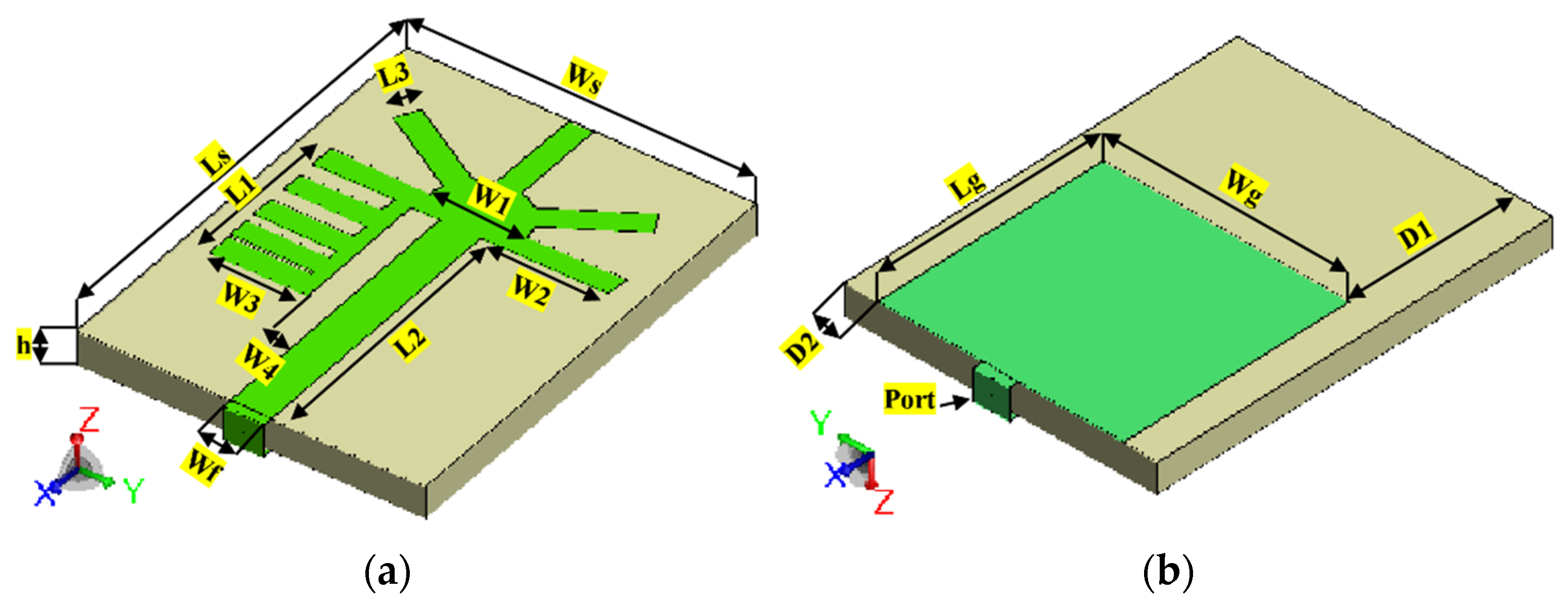
- Antenna 1: a planar monopole with a slotted radiator and fed using a coplanar waveguide (CPW). This antenna was designed on a flexible Kapton polyimide film with a thickness of 0.11 mm, whereas 0.01 mm-thick aluminum foil is used as its conductive sections (radiator, ground plane, and feedline).
- Antenna 2: a planar monopole with a spring-like radiator and fed using a microstrip line. The antenna is designed on textiles, with a 3 mm thick felt as the substrate and ShieldIt conductive textile (0.17 mm thickness) forming the conductive sections.
2. Antenna Configuration
2.1. Antenna 1: Topology
- The antenna has moderate gain and wide bandwidth in free space.
- Additionally, the fabricated antenna demonstrates good radiative properties when operating on both rigid and curved surfaces, making it suitable for different wearable communications applications.

2.1.1. Antenna 1: Design Procedure
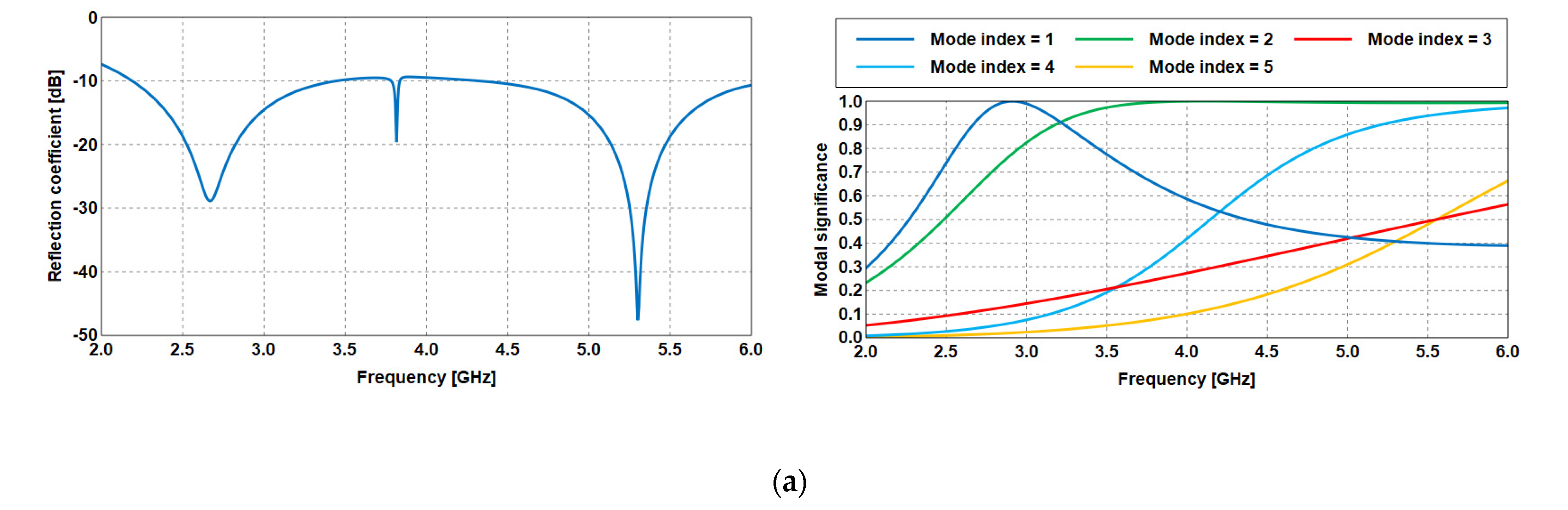
- As the first step, a conventional circular patch antenna is designed. In this iteration, the antenna is not matched at the resonant frequencies from 2 to 2.2 GHz. Similarly, no modes are active to cover this range of frequencies, as illustrated in the MS plot in Figure 3a.
- Next, the antenna in the previous step is modified in step 2. A portion from the upper part of the circular patch is removed to achieve miniaturization at the same resonance, as shown in Figure 3b.
- The antenna is further modified by adding two rectangular parasitic patches on the left and right sides of the radiator. It is observed that the antenna operated with a 10-dB reflection coefficient starting from 2 GHz, which is generated by mode 1, as in Figure 3c. However, the reflection coefficient in this step shows a narrowband around 3 GHz, which does not meet the targeted wideband antenna operation.
- To overcome this, the top side of the patch is extended by connecting a rectangular-shaped resonator. Using this step, the proposed antenna achieved a bandwidth from 2 GHz to 6 GHz, as shown in Figure 3d. Some differences between the estimated operating bandwidth using the MoM and CMA approaches originates from the effect of the excitation process in generating the excited modes.
2.1.2. Results and Discussions
- Antenna Performance in Free Space
- b.
- Gain Estimation using EMC Method based CMA
- i.
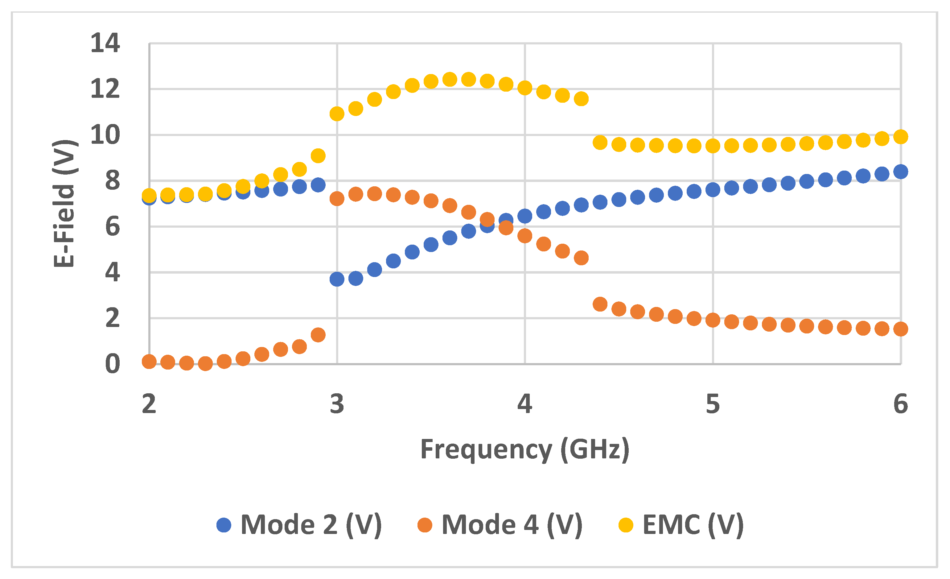
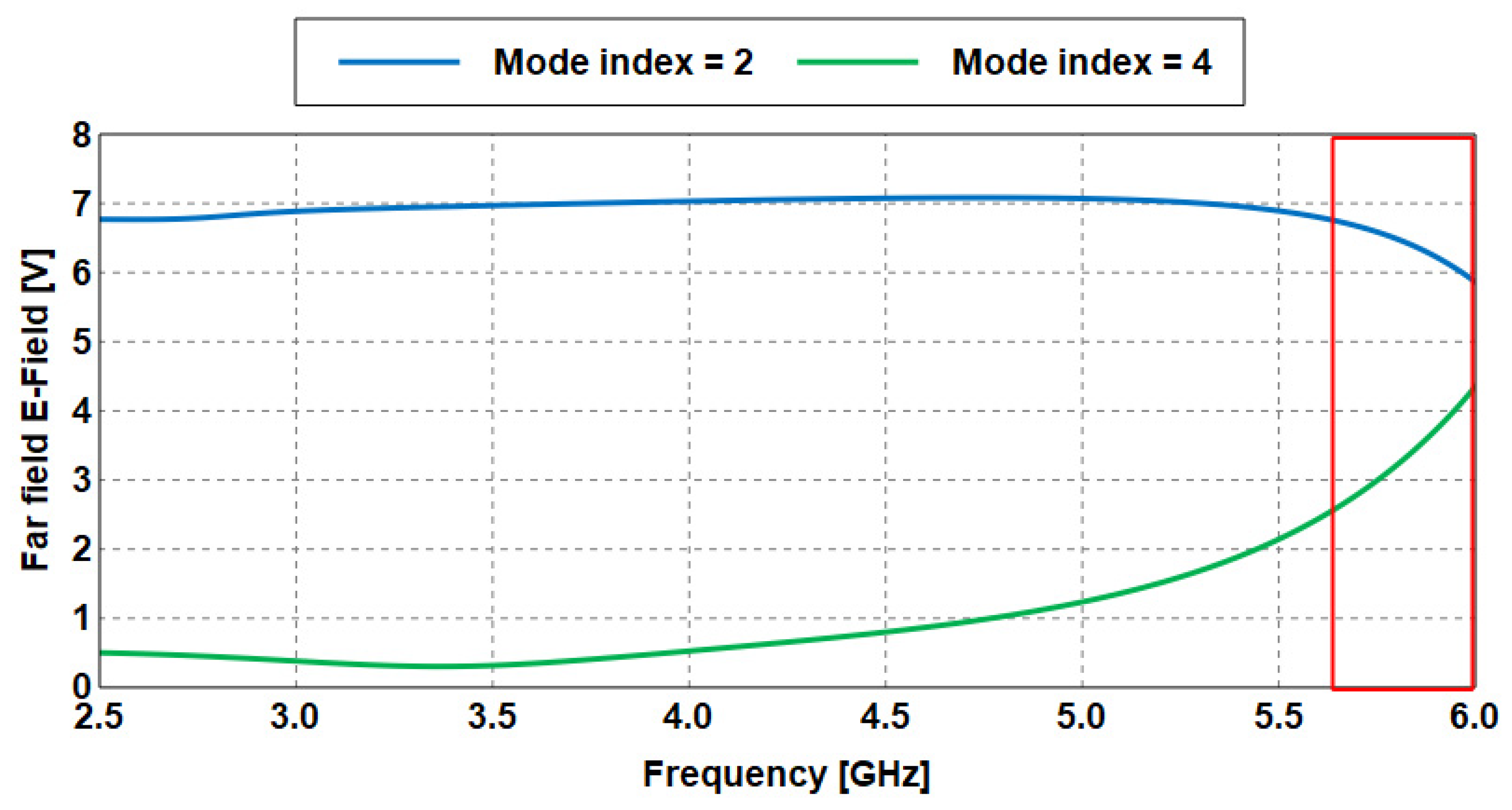
- Based on characteristic mode (CM) theory, the proposed Antenna 1 is first analyzed with only the perfect conductor (patch) and without any substrate, ground, and excitation to determine the natural modes of resonance.
- ii.
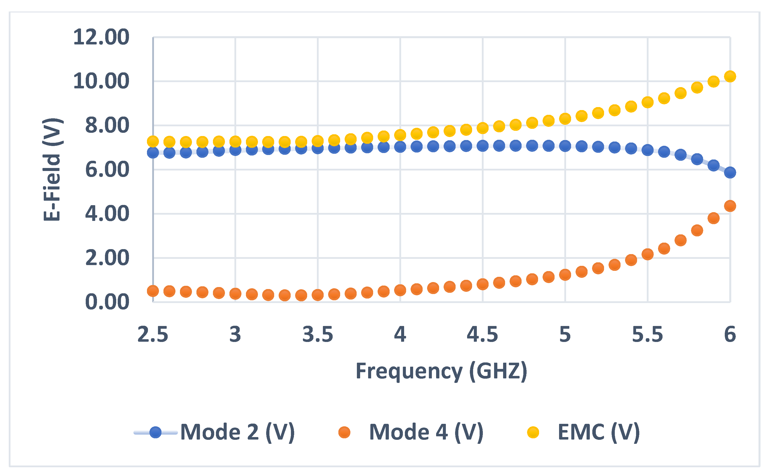
- After the simulation process is performed, the electric field of the first two even modes (mode 2 and mode 4) is obtained from the results, as illustrated in Figure 7.
- iii.
- Next, these two modes are then combined to form a wide specific band (from 2 to 6 GHz) as represented in Equation (1). For example, at 3.7 GHz, the electric field of mode 2 is 5.79 V, whereas it is 6.62 V at mode 4. Then, the EMC method is applied as follows:
- iv.
- The same procedure is performed for the rest of the frequencies. In Table 1, a set of frequencies is selected to verify the proposed method. The results of EMC in the fourth column are arranged in descending order (from the highest value of the electric field to the lowest), as also seen in Figure 8.


- v.
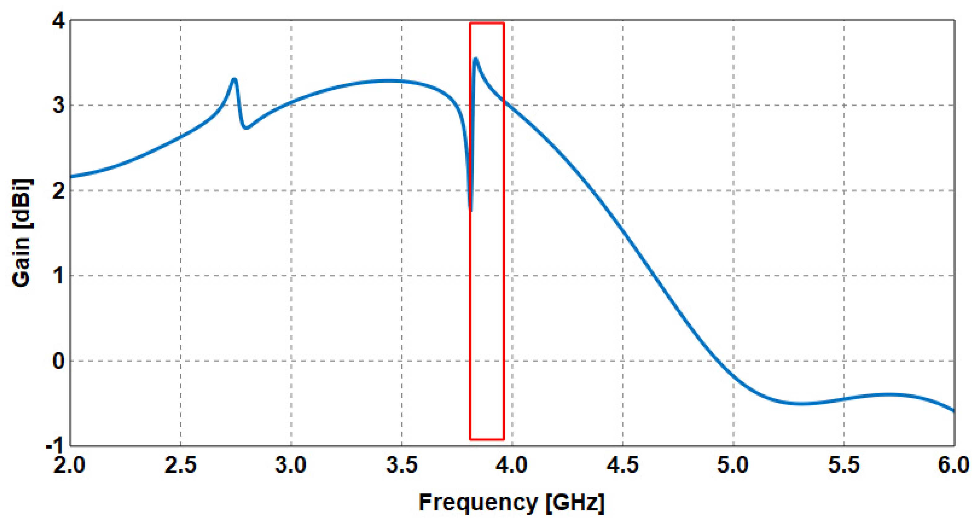
- Finally, the radiating patch is integrated with the substrate and excitation to form the complete antenna. Analysis indicated that the maximum gain of 3.54 dBi is achieved at 3.83 GHz, as indicated in the red box in Figure 9. Note that the frequency at which a maximum electric field was achieved based on the EMC-based CMA method agrees closely with the frequency of the maximum gain of the overall antenna.
2.2. Antenna 2: Topology
- a.
- b.
- c.
- Higher gains are achieved compared with most of the reported antennas in the literature at the relevant frequency (considering the equivalent electrical sizes).
3. Conclusions
Author Contributions
Funding
Data Availability Statement
Conflicts of Interest
References
- Girija, H.S.; Sudhakar, R.; Kadhar, K.M.A.; Priya, T.S.; Ramanathan, S.; Anand, G. PSO Based Microstrip Patch Antenna Design for ISM Band. In Proceedings of the 2020 6th International Conference on Advanced Computing and Communication Systems (ICACCS), Coimbatore, India, 6–7 March 2020; pp. 1209–1214. [Google Scholar] [CrossRef]
- Li, E.; Li, X.J.; Zhao, Q. A Design of Ink-Printable Triband Slot Microstrip Patch Antenna for 5G Applications. In Proceedings of the 4th Australian Microwave Symposium (AMS), Sydney, Australia, 13–14 February 2020. [Google Scholar] [CrossRef]
- Li, T.; Dong, Y.; Fan, P.; Ben Letaief, K. Wireless Communications with RF-Based Energy Harvesting: From Information Theory to Green Systems. IEEE Access 2017, 5, 27538–27550. [Google Scholar] [CrossRef]
- Hussain, N.; Awan, W.A.; Naqvi, S.I.; Ghaffar, A.; Zaidi, A.; Iftikhar, A.; Li, X.J. A Compact Flexible Frequency Reconfigurable Antenna for Heterogeneous Applications. IEEE Access 2020, 8, 173298–173307. [Google Scholar] [CrossRef]
- Soh, P.J.; Vandenbosch, G.; Wee, F.H.; Van den Bosch, A.; Martinez-Vazquez, M.; Schreurs, D. Specific Absorption Rate (SAR) Evaluation of Textile Antennas. IEEE Antennas Propag. Mag. 2015, 57, 229–240. [Google Scholar] [CrossRef]
- Elias, B.B.Q.; Soh, P.J.; Al-Hadi, A.A.; Akkaraekthalin, P.; Vandenbosch, G.A.E. A Review of Antenna Analysis Using Characteristic Modes. IEEE Access 2021, 9, 98833–98862. [Google Scholar] [CrossRef]
- Bauer, J.E.; Gentner, P.K. Characteristic Mode Analysis of a Circular Polarised Rectangular Patch Antenna. In Proceedings of the 2019 13th European Conference on Antennas and Propagation (EuCAP), Krakow, Poland, 31 March–5 April 2019; pp. 1–3. [Google Scholar]
- Mahlaoui, Z.; Antonino-Daviu, E.; Latif, A.; Ferrando-Bataller, M. From the Characteristic Modes Analysis to the Design of a Radiation Pattern Reconfigurable Antenna. In Proceedings of the 2019 13th European Conference on Antennas and Propagation (EuCAP), Krakow, Poland, 31 March–5 April 2019; pp. 1–4. [Google Scholar]
- Phung, Q.Q.; Nguyen, T.H.; Michishita, N.; Sato, H.; Koyanagi, Y.; Morishita, H. Characteristic Mode Analysis of U-Shaped Folded Dipole Antenna for WiMAX. In Proceedings of the 2019 International Workshop on Antenna Technology (iWAT), Miami, FL, USA, 3–6 March 2019; pp. 105–107. [Google Scholar]
- Garbacz, R.; Turpin, R. A generalized expansion for radiated and scattered fields. IEEE Trans. Antennas Propag. 1971, 19, 348–358. [Google Scholar] [CrossRef]
- Harrington, R.; Mautz, J. Computation of characteristic modes for conducting bodies. IEEE Trans. Antennas Propag. 1971, 19, 629–639. [Google Scholar] [CrossRef]
- Harrington, R.; Mautz, J. Theory of characteristic modes for conducting bodies. IEEE Trans. Antennas Propag. 1971, 19, 622–628. [Google Scholar] [CrossRef]
- Singh, M.S.; Ghosh, J.; Ghosh, S.; Sarkhel, A. Miniaturized Dual-Antenna System for Implantable Biotelemetry Application. IEEE Antennas Wirel. Propag. Lett. 2021, 20, 1394–1398. [Google Scholar] [CrossRef]
- Si, L.-M.; Lv, X. CPW-Fed Multi-Band Omni-Directional Planar Microstrip Antenna Using Composite Metamaterial Resonator for Wireless Coomunications. Prog. Electromagn. Res. 2008, 83, 133–146. [Google Scholar] [CrossRef]
- Dwivedi, R.P.; Kommuri, U.K. CPW feed dual band and wideband antennas using crescent shape and T-shape stub for Wi-Fi and WiMAX application. Microw. Opt. Technol. Lett. 2017, 59, 2586–2591. [Google Scholar] [CrossRef]
- Liu, W.-C.; Wu, C.-M.; Chu, N.-C. A Compact CPW-Fed Slotted Patch Antenna for Dual-Band Operation. IEEE Antennas Wirel. Propag. Lett. 2010, 9, 110–113. [Google Scholar] [CrossRef]
- Hua, M.; Wang, P.; Zheng, Y.; Yuan, S. Compact tri-band CPW-fed antenna for WLAN/WiMAX applications. Electron. Lett. 2013, 49, 1118–1119. [Google Scholar] [CrossRef]
- Awan, W.A.; Hussain, N.; Naqvi, S.A.; Iqbal, A.; Striker, R.; Mitra, D.; Braaten, B.D. A miniaturized wideband and multi-band on-demand reconfigurable antenna for compact and portable devices. AEU—Int. J. Electron. Commun. 2020, 122, 153266. [Google Scholar] [CrossRef]
- Wu, R.; Wang, P.; Zheng, Q.; Li, R. Compact CPW-fed triple-band antenna for diversity applications. Electron. Lett. 2015, 51, 735–736. [Google Scholar] [CrossRef]
- Elias, B.Q.; Soh, P.J. Design of a Wideband Spring Textile Antenna for Wearable 5G and IoT Applications Using Characteristic Mode Analysis. Prog. Electromagn. Res. M 2022, 112, 177–189. [Google Scholar] [CrossRef]
- Shi, W.; Gao, J.; Cao, Y.; Yu, Y.; Liu, P.; Ma, Y.; Ni, C.; Yan, S. Gain characteristics estimation of heteromorphic RFID antennas using neuro-space mapping. IET Microw. Antennas Propag. 2020, 14, 1555–1565. [Google Scholar] [CrossRef]
- Guha, D.; Chattopadhya, S.; Siddiqu, J.Y. Estimation of Gain Enhancement Replacing PTFE by Air Substrate in a Microstrip Patch Antenna [Antenna Designer’s Notebook]. IEEE Antennas Propag. Mag. 2010, 52, 92–95. [Google Scholar] [CrossRef]
- Mistry, K.; Lazaridis, P.; Zaharis, Z.; Akinsolu, M.; Liu, B.; Loh, T. Accurate antenna gain estimation using the two-antenna method. In Proceedings of the Antennas and Propagation Conference, Atlanta, GA, USA, 7–12 July 2019; p. 29. [Google Scholar] [CrossRef]
- Reis, A.; Sarrazin, F.; Besnier, P.; Pouliguen, P.; Richalot, E. Contactless Antenna Gain Pattern Estimation from Backscattering Coefficient Measurement Performed within a Reverberation Chamber. IEEE Trans. Antennas Propag. 2021, 70, 2318–2321. [Google Scholar] [CrossRef]
- Wu, S.; Hughes, B.L. A principal-component approach to antenna impedance estimation at MISO receivers. IEEE Commun. Lett. 2023, 27, 288–292. [Google Scholar] [CrossRef]
- Liang, T.; Wang, Z.; Dong, Y. Estimation of axial ratio of single-port dual-mode circularly polarized antenna using reflection coefficient. IEEE Trans. Antennas Propag. 2023, 71, 1706–1715. [Google Scholar] [CrossRef]
- Krouka, W.; Sarrazin, F.; Besnier, P.; Richalot, E. Biased Estimation of Antenna Radiation Efficiency within Reverberation Chambers Due to Unstirred Field: Role of Antenna Stirring. IEEE Trans. Antennas Propag. 2022, 70, 9742–9751. [Google Scholar] [CrossRef]
- Klink, K.; Meyer, P.; Steyn, W. Efficient Yield Estimation of Multiband Patch Antennas Using NLPLS-Based PCE. IEEE Trans. Antennas Propag. 2022, 70, 7037–7045. [Google Scholar] [CrossRef]
- Sharma, R.; Potnis, A.; Chaurasia, V. Modelling of dielectric resonator based filtenna covering 2.5/2.6 (B41/n41) bands using machine learning algorithms. AEU—Int. J. Electron. Commun. 2023, 164, 154642. [Google Scholar] [CrossRef]
- Piltan, O.C.; Kizilay, A.; Belen, M.A.; Mahouti, P. Data driven surrogate modeling of horn antennas for optimal determination of radiation pattern and size using deep learning. Microw. Opt. Technol. Lett. 2023. early view. [Google Scholar] [CrossRef]
- Ali, E.M.; Awan, W.A.; Alzaidi, M.S.; Alzahrani, A.; Elkamchouchi, D.H.; Falcone, F.; Ghoneim, S.S.M. A Shorted Stub Loaded UWB Flexible Antenna for Small IoT Devices. Sensors 2023, 23, 748. [Google Scholar] [CrossRef] [PubMed]
- Yang, H.; Liu, X.; Fan, Y.; Xiong, L. Dual-Band Textile Antenna with Dual Circular Polarizations Using Polarization Rotation AMC for off-Body Communications. IEEE Trans. Antennas Propag. 2022, 70, 4189–4199. [Google Scholar] [CrossRef]
- Li, H.; Du, J.; Yang, X.-X.; Gao, S. Low-Profile All-Textile Multiband Microstrip Circular Patch Antenna for WBAN Applications. IEEE Antennas Wirel. Propag. Lett. 2022, 21, 779–783. [Google Scholar] [CrossRef]
- Yang, H.; Liu, X. Screen-Printed Dual-Band and Dual-Circularly Polarized Textile Antenna for Wearable Applications. In Proceedings of the 15th European Conference on Antennas and Propagation (EuCAP), Dusseldorf, Germany, 22–26 March 2021. [Google Scholar] [CrossRef]
- Zhou, L.; Fang, S.; Jia, X. Dual-band and dual-polarised circular patch textile antenna for on-/off-body WBAN applications. IET Microw. Antennas Propag. 2020, 14, 643–648. [Google Scholar] [CrossRef]
- Yang, H.; Liu, X. Wearable Dual-Band and Dual-Polarized Textile Antenna for on- and off-Body Communications. IEEE Antennas Wirel. Propag. Lett. 2020, 19, 2324–2328. [Google Scholar] [CrossRef]
- Yan, S.; Volskiy, V.; Vandenbosch, G.A.E. Compact Dual-Band Textile PIFA for 433-MHz/2.4-GHz ISM Bands. IEEE Antennas Wirel. Propag. Lett. 2017, 16, 2436–2439. [Google Scholar] [CrossRef]
- Sayem, A.S.M.; Simorangkir, R.B.V.B.; Esselle, K.P.; Hashmi, R.M. Development of Robust Transparent Conformal Antennas Based on Conductive Mesh-Polymer Composite for Unobtrusive Wearable Applications. IEEE Trans. Antennas Propag. 2019, 67, 7216–7224. [Google Scholar] [CrossRef]
- Hamouda, Z.; Wojkiewicz, J.-l.; Pud, A.A.; Kone, L.; Bergheul, S.; Lasri, T. Flexible UWB organic antenna for wearable technologies application. IET Microw. Antennas Propag. 2018, 12, 160–166. [Google Scholar] [CrossRef]
- Simorangkir, R.B.V.B.; Yang, Y.; Matekovits, L.; Esselle, K.P. Dual-Band Dual-Mode Textile Antenna on PDMS Substrate for Body-Centric Communications. IEEE Antennas Wirel. Propag. Lett. 2016, 16, 677–680. [Google Scholar] [CrossRef]


| Frequency (GHz) | Mode 2 (V) | Mode 4 (V) | EMC (V) |
|---|---|---|---|
| 3.7 | 5.79 | 6.62 | 12.42 |
| 3.6 | 5.51 | 6.91 | 12.42 |
| 3.8 | 6.04 | 6.31 | 12.34 |
| 3.5 | 5.21 | 7.12 | 12.33 |
| 3.9 | 6.27 | 5.94 | 12.21 |
| 3.4 | 4.88 | 7.28 | 12.16 |
| 4 | 6.46 | 5.59 | 12.05 |
| 3.3 | 4.49 | 7.38 | 11.88 |
| 4.1 | 6.64 | 5.23 | 11.87 |
| 4.2 | 6.79 | 4.93 | 11.72 |
| 4.3 | 6.93 | 4.63 | 11.57 |
| 3.2 | 4.12 | 7.43 | 11.55 |
| 3.1 | 3.74 | 7.41 | 11.15 |
| 3 | 3.69 | 7.22 | 10.92 |
| 6 | 8.39 | 1.52 | 9.92 |
| 5.9 | 8.29 | 1.54 | 9.83 |
| 5.8 | 8.21 | 1.56 | 9.76 |
| 5.7 | 8.12 | 1.59 | 9.71 |
| 4.4 | 7.05 | 2.61 | 9.67 |
| 5.6 | 8.03 | 1.62 | 9.66 |
| 5.5 | 7.97 | 1.65 | 9.62 |
| 5.4 | 7.89 | 1.69 | 9.58 |
| 4.5 | 7.18 | 2.41 | 9.58 |
| 5.3 | 7.82 | 1.74 | 9.56 |
| 4.6 | 7.27 | 2.28 | 9.55 |
| 5.2 | 7.75 | 1.79 | 9.54 |
| 4.7 | 7.37 | 2.17 | 9.54 |
| 5.1 | 7.68 | 1.85 | 9.53 |
| 4.8 | 7.45 | 2.07 | 9.53 |
| 5 | 7.61 | 1.91 | 9.52 |
| 4.9 | 7.53 | 1.98 | 9.52 |
| 2.9 | 7.82 | 1.27 | 9.08 |
| 2.8 | 7.73 | 0.76 | 8.49 |
| 2.7 | 7.63 | 0.64 | 8.27 |
| 2.6 | 7.56 | 0.42 | 7.99 |
| 2.5 | 7.51 | 0.24 | 7.74 |
| 2.4 | 7.45 | 0.11 | 7.57 |
| 2.3 | 7.39 | 0.02 | 7.42 |
| 2.2 | 7.34 | 0.04 | 7.39 |
| 2.1 | 7.29 | 0.08 | 7.37 |
| 2 | 7.24 | 0.11 | 7.35 |
| Frequency (GHz) | Mode 2 (V) | Mode 4 (V) | EMC (V) |
|---|---|---|---|
| 6 | 5.86 | 4.35 | 10.22 |
| 5.9 | 6.19 | 3.80 | 9.99 |
| 5.8 | 6.47 | 3.25 | 9.72 |
| 5.7 | 6.67 | 2.79 | 9.46 |
| 5.6 | 6.81 | 2.42 | 9.23 |
| 5.5 | 6.89 | 2.16 | 9.05 |
| 5.4 | 6.96 | 1.90 | 8.86 |
| 5.3 | 7.00 | 1.68 | 8.69 |
| 5.2 | 7.03 | 1.53 | 8.56 |
| 5.1 | 7.06 | 1.37 | 8.43 |
| 5 | 7.07 | 1.23 | 8.30 |
| 4.9 | 7.08 | 1.14 | 8.21 |
| 4.8 | 7.08 | 1.03 | 8.11 |
| 4.7 | 7.08 | 0.94 | 8.03 |
| 4.6 | 7.08 | 0.88 | 7.96 |
| 4.5 | 7.08 | 0.80 | 7.88 |
| 4.4 | 7.07 | 0.74 | 7.81 |
| 4.3 | 7.06 | 0.69 | 7.75 |
| 4.2 | 7.05 | 0.63 | 7.68 |
| 4.1 | 7.04 | 0.58 | 7.62 |
| 4 | 7.03 | 0.53 | 7.57 |
| 3.9 | 7.02 | 0.48 | 7.50 |
| 3.8 | 7.01 | 0.43 | 7.44 |
| 3.7 | 6.99 | 0.38 | 7.38 |
| 3.6 | 6.98 | 0.35 | 7.33 |
| 3.5 | 6.97 | 0.32 | 7.29 |
| 2.5 | 6.77 | 0.50 | 7.27 |
| 3 | 6.89 | 0.38 | 7.27 |
| 2.9 | 6.85 | 0.41 | 7.27 |
| 3.4 | 6.96 | 0.30 | 7.26 |
| 3.1 | 6.91 | 0.35 | 7.26 |
| 2.6 | 6.77 | 0.49 | 7.25 |
| 2.8 | 6.81 | 0.44 | 7.25 |
| 3.2 | 6.93 | 0.32 | 7.25 |
| 3.3 | 6.94 | 0.31 | 7.25 |
| 2.7 | 6.78 | 0.47 | 7.24 |
| Ref | Study | Method Used | Advantages |
|---|---|---|---|
| [21] | Gain characteristics estimation of heteromorphic RFID antennas using neurospace mapping. | Gain estimation method for heteromorphic RF identification (RFID) antennas, built on the basis of neuro-SM technique. | Effectively reduces time consumption and avoids laborsome measurement processes. |
| [22] | Estimation of gain enhancement replacing PTFE by air substrate in a microstrip patch antenna. | Replacing PTFE by air substrate. | Very handy and useful to a designer dealing with air-substrate microstrip antennas. |
| [23] | Accurate antenna gain estimation using the two-antenna method. | Two-antenna gain determination method using Friis equation. | Eliminates the need to perform the measurement at various separation distances. |
| [24] | Contactless gain pattern estimation from backscattering coefficient measurement performed within a reverberation chamber. | Evaluated for the first time from the backscattering coefficient measured within a reverberation chamber. | The antenna backscattering coefficient is measured for two load conditions, namely, an open circuit and a 50 load. This distinguishes the radiation and structural modes from the total backscattered field. |
| [25] | A principal-component approach to antenna impedance estimation at MISO receivers. | Study the antenna impedance estimation at MISO receivers over Rayleigh fading channels and derive the optimal ML estimator in closed-form. | Numerical results suggest a computationally efficient, principal-components approach that estimates antenna impedance in real-time and shows sizable improvement against a reference estimator at low SNR. |
| [26] | Estimation of the axial ratio of the single-port dual-mode circularly polarized antenna using reflection coefficient. | The estimation method applies to a single-port CP antenna that is composed of two resonant modes with orthogonal polarization and 90° phase difference. | Simple way to can estimate the axial ratio (AR) of a circularly polarized (CP) antenna Illustrates the source of estimation errors and proves that the method reaches acceptable AR estimation without time-consuming microwave chamber measurement Provides a new perspective to high-speed pre-test and tuning for volume production of CP antennas. |
| [27] | Biased estimation of antenna radiation efficiency within reverberation chambers due to the unstirred field: role of antenna stirring. | Four measurement campaigns were successively performed: without antenna stirring, with platform stirring only, with source stirring only, and with a combined stirring of both antennas. | An extensive study on the role of antenna stirring in the retrieved radiation efficiency. Performing only source stirring or platform stirring leads to a biased estimation of the radiation efficiency. |
| [28] | Efficient yield estimation of multiband patch antennas using NLPLS-based PCE. | The tolerances associated with the fabrication process are applied to the statistically significant system parameters, and a Monte Carlo (MC) simulation is completed to accurately estimate the yield. | NLPLS-based PCE effectively reduces the system dimensionality using NLPLS and simultaneously extracts the statistical information on the same sample set (yield) using PCE. A solution for complex antenna yields analysis. |
| [29] | Modelling of dielectric resonator based filtenna for 2.5/2.6 (B41/n41) bands using machine learning algorithms. | Different parameters of the proposed antenna, such as reflection coefficient and gain, are optimized and predicted using different machine learning (ML) techniques, i.e., deep neural network (DNN), random forest, and XG boost. | An optimized value obtained from various ML algorithms is compared with the value obtained HFSS EM simulator and experimental result. Good agreement is obtained among all of them. |
| [30] | Data-driven surrogate modeling of horn antennas for optimal determination of radiation pattern and size using deep learning. | The geometrical design variables, operation frequency, and radiation direction of the design taken as the input, while the realized gain of the design is taken as the output of the surrogate model. Series of powerful and commonly used artificial intelligence algorithms, including deep learning, had been used to create a data-driven surrogate model. | Achieve a computationally efficient design optimization process for horn antennas with high radiation performance, besides being small in or within the limits of the desired application. A total of 80% computational cost reduction was obtained via the proposed approach. |
| This work | Resonance analysis and gain estimation of a wideband antenna using CMA. | EMC method based on characteristic mode analysis. | Estimates the gain of the antenna without using substrate, ground, and excitation, offering efficient time cost in the simulation process. |
| Ref | Size of the Antenna (λg) | Substrate Material | Operating Frequency (GHz) | Bandwidth (%) | Gain (dBi) | Flexible? | Year |
|---|---|---|---|---|---|---|---|
| [31] | 0.27 × 0.2 × 0.003 | Rogers 5880 | 3.5/6.8/9 | 112 | >2.5 | Yes | 2023 |
| [32] | 0.83 × 0.83 × 0.073 | Felt | 3.5/5.8 | 11.7/9.1 | 6.6/7.2 | Yes | 2022 |
| [33] | 0.64 × 0.64 × 0.0125 | Denim | 2.45/3.32/ 3.93/5.8 | 3.7/5.7/ 5.85/9.8 | −0.81/−2.81/−1.16/2.83 | Yes | 2022 |
| [34] | 0.83 × 0.83 × 0.053 | Felt | 3.5/5.8 | 12.5/11.6 | 6/5.8 | Yes | 2021 |
| [35] | 0.89 × 0.89 × 0.018 | Felt | 2.45/5.8 | 4.9/3.8 | 5.93/6.02 | Yes | 2020 |
| [36] | 0.63 × 0.63 × 0.018 | Felt | 2.38/3.5 | 4.1/7.0 | 1.38/7.7 | Yes | 2020 |
| [37] | 1.3 × 0.74 × 0.059 | Felt | 0.433/2.45 | 8.1/12.6 | −0.5/6.1 | Yes | 2017 |
| [38] | 0.79 × 0.68 × 0.041 | PDMS | 2.43/5.15 | 8.2/17.5 | 2.2/3.02 | Yes | 2019 |
| [39] | 0.3 × 0.21 × 0.0006 | conductive polymer (PANI/MWCNTs) | 2.2/5.3 | 45/60 | 3.1 dBi at 5.8 GHz | Yes | 2018 |
| [40] | 0.48 × 0.48π × 0.041 | PDMS | 2.45/5.8 | 3.3/4.17 | 4.16/4.34 | Yes | 2017 |
| Prop. | 0.69 × 0.69 × 0.001 | Kapton polyimide film | 2.45/3.6/5.5/5.8 Wideband (2–6 GHz) | 100 | 5/8/4/4 | Yes | 2023 |
Disclaimer/Publisher’s Note: The statements, opinions and data contained in all publications are solely those of the individual author(s) and contributor(s) and not of MDPI and/or the editor(s). MDPI and/or the editor(s) disclaim responsibility for any injury to people or property resulting from any ideas, methods, instructions or products referred to in the content. |
© 2023 by the authors. Licensee MDPI, Basel, Switzerland. This article is an open access article distributed under the terms and conditions of the Creative Commons Attribution (CC BY) license (https://creativecommons.org/licenses/by/4.0/).
Share and Cite
Qas Elias, B.B.; Soh, P.J. Resonance Analysis and Gain Estimation Using CMA-Based Even Mode Combination Method for Flexible Wideband Antennas. Sensors 2023, 23, 5297. https://doi.org/10.3390/s23115297
Qas Elias BB, Soh PJ. Resonance Analysis and Gain Estimation Using CMA-Based Even Mode Combination Method for Flexible Wideband Antennas. Sensors. 2023; 23(11):5297. https://doi.org/10.3390/s23115297
Chicago/Turabian StyleQas Elias, Bashar Bahaa, and Ping Jack Soh. 2023. "Resonance Analysis and Gain Estimation Using CMA-Based Even Mode Combination Method for Flexible Wideband Antennas" Sensors 23, no. 11: 5297. https://doi.org/10.3390/s23115297
APA StyleQas Elias, B. B., & Soh, P. J. (2023). Resonance Analysis and Gain Estimation Using CMA-Based Even Mode Combination Method for Flexible Wideband Antennas. Sensors, 23(11), 5297. https://doi.org/10.3390/s23115297