Abstract
This paper proposes a device that can change the payload of an unpowered lower-limb exoskeleton supporting the weights of humans and loads. Our previous exoskeletons used a cam–follower structure with a spring applied to the hip joint. This exoskeleton showed satisfying performance within the payload; however, the performance decreased when the payload was exceeded. Therefore, a payload adjustment device that can adjust the wearer’s required torque by easily applying it to the cam–follower structure was developed. An exoskeleton dynamic equation that can calculate a person’s required joint torque given the required payload and the wearer’s posture was derived. This dynamic equation provides a guideline for designing a device that can adjust the allowable joint torque range of an unpowered exoskeleton. In the Adams simulation environment, the payload adjustment device is applied to the cam–follower structure to show that the payload of the exoskeleton can be changed. User convenience and mass production were taken into account in the design of this device. This payload adjustment device should flexibly change the payload of the level desired by the wearer because it can quickly change the payload of the exoskeleton.
Keywords:
human assistance; unpowered; exoskeleton; payload; variable stiffness; torque compensation 1. Introduction
Exoskeletons have been studied to assist humans and have been developed for strengthening the wearer’s muscles and rehabilitation treatment [1,2,3,4,5,6,7,8]. Exoskeletons can also be classified according to their structure. First, a free-joint-type exoskeleton has a joint stiffness of 0, as measured at the joint [9,10,11,12,13]. This exoskeleton has the advantage of moving freely because there is no element hindering the wearer’s movement, but there is a limitation in that it cannot compensate for the external force acting on a person. Second, a rigid-joint-type exoskeleton has exceptionally high joint stiffness measured at the joint [14,15,16,17,18], effectively limiting joint movement. It is mainly applied to exoskeletons for rehabilitation because it can restrain the wearer’s unnecessary movements. Third, in an active-joint-type exoskeleton, actuators are applied to the joints to work in synchronization with the wearer’s intention [19,20,21,22,23,24,25,26,27]. The exoskeleton needs a battery to drive, and the actuator’s output torque must be large because the actuator must assist human movement. Finally, a quasi-passive joint type exoskeleton refers to an exoskeleton to which elements with specific stiffness are applied to the joint [28,29,30,31,32,33,34,35]. This exoskeleton has elastic elements, such as springs used to generate joint torque, and the stiffness of these elastic elements can be adjusted using an actuator.
The exoskeleton requires a large joint torque capacity to assist humans. The active-joint-type exoskeleton must apply a reducer with a high reduction ratio to the actuator to realize a large torque capacity. By using a speed reducer with a high reduction ratio, a tradeoff occurs between the torque and speed relationship and reduces the performance of the exoskeleton’s backdrivability. Therefore, the exoskeleton is prevented from responding quickly to situations where the supply power of the actuator used in the exoskeleton is cut off or a person must move rapidly [36] (e.g., a situation where the actuator does not work properly while walking, so the wearer must quickly step into a stable position or a situation where a person suddenly changes the direction of walking). This is causally related to the safety problem for the user.
Regarding an active-joint-type exoskeleton, it is known that stability and speed are indirectly proportional [37]. In other words, it can be said that the active-joint-type exoskeleton has difficulty coping with a person’s sudden movement. As a way to solve these problems to some extent, the passive-joint-type exoskeleton or the quasi-passive joint type exoskeleton can be one way to overcome this safety issue [38]. A variable stiffness actuator (VSA) has been developed to increase the allowable joint torque of a quasi-passive joint type exoskeleton [39,40,41]. The exoskeleton with a VSA can increase the torque that can be generated in the exoskeleton’s joints by controlling stiffness through an actuator. However, the quasi-passive joint type exoskeleton with a VSA requires a power source because it uses an actuator; therefore, stiffness cannot be adjusted when the power source is cut off. If the power is cut off when the stiffness is increased, the same problems as in the active-joint-type exoskeleton are caused. Additionally, using the power source requires additional components, thereby increasing the complexity of the system. Furthermore, it is not energy efficient and economical, as it consumes additional energy.
An active-joint-type exoskeleton will inevitably cause the aforementioned safety issue, is structurally complex, and has a high price [37,38]. Because actuators are also used in the quasi-passive joint type exoskeleton, problems that occur in the active-joint-type exoskeleton may also occur and increase the structural complexity due to the addition of an actuator. Considering the safety issues of the active-joint-type exoskeleton and the economy of the quasi-passive joint type exoskeleton, a passive-joint-type unpowered exoskeleton without actuators and power supplies was designed. In previous studies, it is confirmed that this designed exoskeleton has sufficient torque compensation when a person is standing or walking with an object [42]. However, in this exoskeleton system, because the payload change is not considered, it has a limitation that it cannot flexibly respond to the user’s requested payload change. Therefore, an unpowered payload adjustment device that can quickly change this payload was developed.
To design a payload adjustment device, a dynamic equation that can calculate the exoskeleton joint torque required by the wearer according to the required payload and the exoskeleton’s current posture is derived. A design guideline for fabricating an unpowered exoskeleton using this dynamic equation is proposed. In the Adams simulation environment, the validity of the dynamic equation derived was verified, and it was confirmed that the proposed payload adjustment device enables the payload adjustment.
2. Approach Method
2.1. Design Goal
Figure 1 shows the exoskeleton designed in the previous study (Figure 1a) and the exoskeleton to which the payload adjustment device proposed in this paper is applied (Figure 1b). In Figure 1a, the exoskeleton has a hip joint, knee joint, and ankle joint and is in front of the person. Figure 1b shows the figure in which the red payload adjustment device is applied to the exoskeleton shown in Figure 1a and is an enlarged view of the hip joint shown in Figure 1a.
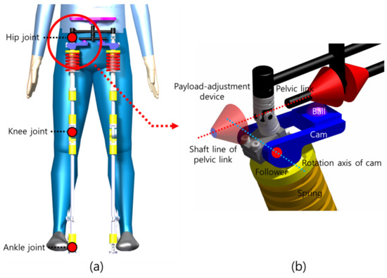
Figure 1.
Schematic of the exoskeleton: (a) previous model; (b) new model with a payload adjustment device.
In Figure 1b, the exoskeleton consists of a black pelvic link, blue cam, yellow follower, spring in contact with the follower, and red payload adjustment device. The payload adjustment device can be disassembled and combined along the axis of the pelvic link. The ball mounted on the cam is in contact with the pelvic link to which the payload adjustment device is applied, and the cam rotates based on the cam’s rotation axis. This structured system creates degrees of freedom for the hip joint and enables reaction force generation through the cam–follower structure.
The only method to change the payload of the exoskeleton proposed in the previous study was to change the shape of the cam or the spring constant. Changing the spring constant has the disadvantage that it takes longer to disassemble and assemble the part, and changing the shape of the cam has the disadvantage that the structural design becomes complicated. Therefore, the design goal is set in a direction that does not increase the complexity of the design so that users can easily disassemble and assemble it.
To achieve this design goal, the reaction force generated at the contact point of the pelvic link and ball instead of changing the conventional cam shape and spring stiffness was focused on. Like the red part shown in Figure 1b, the reaction force can be changed by changing the shape of the pelvic link. The changed reaction force changes the force applied to the spring and, consequently, the payload of the exoskeleton. The red payload adjustment device in Figure 1b is combined with the shaft of the pelvic link and has no direction to the shaft line; therefore, it is easy for the exoskeleton wearer to quickly disassemble and assemble. Furthermore, this device is economical because of its uncomplicated structure and easy processing.
2.2. Derivation of Dynamic Equations
To determine the shape of the payload adjustment device proposed in Section 2.1, the relationship between the shape of the payload adjustment device and the joint torque is derived. Figure 2 shows the exoskeleton to which the payload adjustment device is applied. The device is cone-shaped, and the inclination angle is set to . The exoskeleton’s hip adduction angle is defined as . represents the center of rotation of the exoskeleton’s hip joint, and and represent the cam’s center of rotation before and after hip adduction of the exoskeleton, respectively. and represent the center of the ball before and after hip adduction of the exoskeleton, respectively, and and represent the contact point between the ball and the pelvic link before and after hip adduction of the exoskeleton, respectively. represents the angle between and the thigh link, and represents . To derive the dynamic equation of this system, and should first be defined. The kinematic equations are
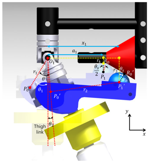
Figure 2.
Kinematic system in the proposed exoskeleton.
Therefore, and are defined using Equations (1) and (2). Here represents , and represents . represents the -axis distance from to , and represents the -axis distance from to . represents the radius of the ball. represents the -axis distance from to when the hip adduction angle () is 0 rad, and represents the -axis distance from to when the hip adduction angle is rad ( ≠ 0 rad).
Figure 3 shows the force generated at the joint and contact point when the exoskeleton’s hip adduction angle is . represents the contact point of the cam and follower, and represents the cam’s center of mass. represents the pelvic link’s center of mass. represents , and represents . represents the -axis reaction force generated in , represents the -axis reaction force generated in , and represents the -axis reaction torque generated in . represents the -axis reaction force generated in , and represents the -axis reaction force generated in . represents the weight of the cam acting on . represents the spring force acting on . represents the reaction force generated at . represents the weight of an object carried by a person acting on , and represents the weight of one leg of the exoskeleton.
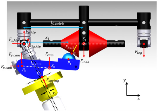
Figure 3.
Dynamic system in the proposed exoskeleton.
The single support phase that requires the most energy when a person walks is focused on, and the system shown in Figure 3 is a model assuming this situation. Compared to , is assumed to be the point mass because the force is small. The hip abduction torque () for the hip adduction angle () is defined as
Therefore, the hip abduction torque () for the hip adduction angle () according to the inclination angle () is defined using Equation (3).
2.3. Assembly Process of the Proposed Device
Figure 4a–d shows the assembly diagram of the payload adjustment device. The assembly sequence proceeds sequentially. Figure 4a shows the exoskeleton before the payload adjustment device is applied. Because there is no constraint between the ball and the pelvic link in this system, it is not difficult to perform hip abduction at the hip joint of the exoskeleton. After hip abduction of the exoskeleton is performed, there is a space between the hip joint and the pelvic link to assemble the payload adjustment device (Figure 4b). After that, coupling is performed by matching the axis of the payload adjustment device with the axis of the pelvic link (Figure 4c). Finally, when the payload adjustment device is positioned near the center of the pelvic link and the exoskeleton is positioned before hip abduction, the assembly of the payload adjustment device is completed (Figure 4d).
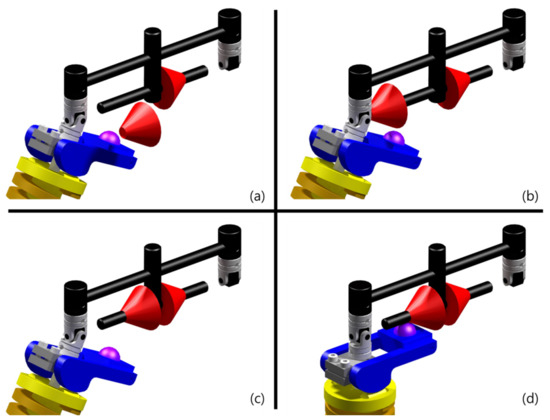
Figure 4.
Assembly diagram of the payload adjustment device: (a) a step before the payload adjustment device is applied; (b) axial alignment of the axis of the pelvic link and the payload adjustment device; (c) coupling of the pelvic link and the payload adjustment device; (d) a step after the payload adjustment device is applied.
3. Simulation
A dynamics simulation in the Adams environment to prove the validity of the calculated dynamics equations was performed. Similar to Section 2.2, the experimental environment was constructed, assuming a single support phase during the human gait cycle (Figure 5). To evaluate the hip abduction torque measured in the roll direction, the movement in the pitch direction was limited, and consequently, the simulation was performed by excluding the knee joint. In the simulation environment, the spring constant was set to 551 N/mm, the angular velocity at the time of hip adduction was set to 9π/180 rad/s, and the time to perform hip adduction was set to 1 s. For the pelvic link to move horizontally to the ground, the angular velocity of the ankle joint was also set to 9π/180 rad/s, and the time was set to 1 s. was set to 300 N. Figure 6 shows the result of the derived dynamic equation and the Adams simulation result. The percentage error equation was used to check the error between the two result values, and this equation is
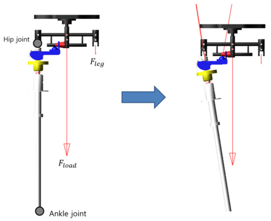
Figure 5.
Adams simulation environment.
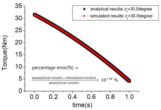
Figure 6.
Comparison of analytical and simulated results.
From Equation (4), the percentage error was less than , which is negligible. Therefore, it was verified that the dynamic equation was properly derived.
Figure 7 is a graph showing versus time according to . represents the difference between the maximum and minimum values of hip abduction torque according to . Therefore, the higher this value is, the higher the payload of the exoskeleton. When is 0.0 degrees, it indicates the model to which the payload adjustment device is not applied. As shown in Figure 7, it was confirmed that increased as increased. Therefore, when the hip adduction angle is the same, the large means that the weight of the load that the spring can support is large. It was calculated as and , showing a maximum torque increase rate of ~85.1%. That is, if the payload adjustment device was applied, the torque increase rate was up to 85.1%.
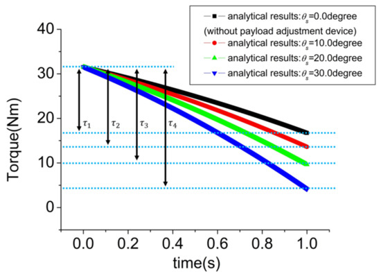
Figure 7.
Hip joint torques when the exoskeleton with a payload adjustment device performs hip adduction.
4. Discussion
Previously designed exoskeletons have shown that despite being unpowered, they can provide sufficient assistance for a person when standing or walking with objects. However, because the change of the exoskeleton’s payload was not considered in this system, there was a limit to the reduction in the exoskeleton’s performance for objects exceeding the payload. Therefore, a payload adjustment device that can flexibly change the payload of the unpowered exoskeleton was developed. Considering the safety issue when the power is cut off, this device is also designed on an unpowered basis.
Figure 4a shows the exoskeleton to which the payload adjustment device is not applied. Figure 4c shows the exoskeleton to which the payload adjustment device is applied. To increase the payload of this exoskeleton without using a payload adjustment device, it is necessary to change the cam with a different shape or change the spring constant. Both of these methods have a disadvantage in that the adaptation time is long because decomposition and coupling are complicated. However, as shown in Figure 4, the payload adjustment device proposed in this paper is considerably easier to disassemble and combine than the above-mentioned method and also has advantages in terms of cost and time for processing this device because of its simple structure. Therefore, based on these advantages, the payload adjustment device is economical and has high utility because it can quickly respond to changes in the environment.
An Adams simulation environment was constructed to verify the effectiveness of the payload adjustment device, and it was confirmed that the difference in hip abduction torque can occur up to 85.1% depending on whether the payload adjustment device is used or not. That is, it can be judged that the payload of the exoskeleton is increased. As mentioned above, the payload adjustment device proposed in this paper is easy to disassemble and assemble, so it can be replaced immediately according to the user’s usage environment. Therefore, despite the passive-joint-type exoskeleton, it can respond to various environments and can be judged to have the advantage of minimizing safety issues that occur in the active-joint-type exoskeleton.
The payload adjustment device presented in this paper has a limitation in that it cannot obtain a fully optimized torque profile because is constant with time. generated in the exoskeleton to which the payload adjustment device is applied can be expressed as follows.
If and are assumed to be measurable variables, generated in the exoskeleton can be calculated. In addition, if can be changed during hip adduction, it is expected that can be optimized according to the human gait cycle and the weight of the load.
5. Conclusions
A device that can quickly change the payload of a previously designed unpowered exoskeleton was developed. Our former exoskeleton within the payload provided sufficient assistance to a person when standing or walking with an object. However, this exoskeleton had a limit where it was difficult to change the payload. To devise a device that can flexibly change this payload, a dynamic equation from the previously designed exoskeleton with a new design variable added was derived. Experiments were conducted in an Adams simulation environment to prove the validity of the newly derived equation. Finally, the validity of the proposed kinetic equation was verified, and it was confirmed that the joint torque of the exoskeleton was controlled according to the design variable . Therefore, it was confirmed that this could be implemented by changing to generate the wearer’s required level of torque. Our device can be flexibly changed according to the wearer’s working environment because disassembly and assembly can be performed quickly. Our exoskeleton, to which this device is applied, does not have an additional actuator and power supply; therefore, it is highly safe and economical. Furthermore, this device could be applied to legged robots and exoskeleton systems to control joint torque.
In future work, the proposed device is planned to be applied to the previously developed exoskeleton, and as mentioned in the discussion section, research on optimizing the shape of the proposed device according to the human gait cycle and the load is planned.
Author Contributions
Conceptualization, J.Y., O.K. and H.-M.J.; methodology, J.Y., O.K. and H.-M.J.; software, J.Y.; validation, J.Y.; formal analysis, J.Y.; investigation, J.Y.; resources, J.Y.; data curation, J.Y.; writing—original draft preparation, J.Y.; writing—review and editing, H.-M.J.; visualization, J.Y.; supervision, H.-M.J.; project administration, H.-M.J.; funding acquisition, O.K. All authors have read and agreed to the published version of the manuscript.
Funding
This work was supported by the National Research Foundation (NRF), Korea, under project BK21 FOUR. This work was also supported by the National Research Foundation of Korea (NRF) grant funded by the Korean government (Ministry of Science and ICT) (2020R1G1A1101767).
Institutional Review Board Statement
Not applicable.
Informed Consent Statement
Not applicable.
Data Availability Statement
Not applicable.
Conflicts of Interest
The authors declare no conflict of interest.
Nomenclature
| The -axis distance from to | |
| The distance from thigh link to | |
| (0.03265 m) | |
| (0.067469 m) | |
| The -axis distance from to | |
| The -axis distance from to (0.005 m) | |
| The radius of the ball (0.005 m) | |
| The -axis distance from to (0.051 m) | |
| The exoskeleton’s hip adduction angle | |
| The inclination angle of the payload adjustment device | |
| The angle between and the thigh link (0.477345 rad) | |
| (0.0875 m) | |
| The -axis reaction force generated in | |
| The -axis reaction force generated in | |
| The -axis reaction torque generated in | |
| The -axis reaction force generated in | |
| The -axis reaction force generated in | |
| The weight of the cam acting on | |
| The spring force acting on | |
| The reaction force generated at | |
| The weight of an object carried by a person acting on (300 N) | |
| The weight of one leg of the exoskeleton | |
| Mass moment of inertia of the pelvic link () | |
| The second derivative of with respect to time | |
| The difference between the maximum and minimum values of hip abduction torque according to |
References
- Yang, C.; Zhang, J.; Chen, Y.; Dong, Y.; Zhang, Y. A review of exoskeleton-type systems and their key technologies. Proc. Inst. Mech. Eng. H 2008, 222, 1599–1612. [Google Scholar] [CrossRef]
- Hill, D.; Holloway, C.S.; Ramirez, D.Z.M.; Smitham, P.; Pappas, Y. What are user perspectives of exoskeleton technology? A literature review. Int. J. Technol. Assess. Health Care 2017, 33, 160–167. [Google Scholar] [CrossRef]
- Hong, Y.; King, Y.; Yeo, W.; Ting, C.; Chuah, Y.; Lee, J.; Chok, E. Lower extremity exoskeleton: Review and challenges surrounding the technology and its role in rehabilitation of lower limbs. Aust. J. Basic Appl. Sci. 2013, 7, 520–524. [Google Scholar]
- Shi, D.; Zhang, W.; Zhang, W.; Ding, X. A review on lower limb rehabilitation exoskeleton robots. Chin. J. Mech. Eng. 2019, 32, 1–11. [Google Scholar] [CrossRef]
- Li, N.; Yan, L.; Qian, H.; Wu, H.; Wu, J.; Men, S. Review on lower extremity exoskeleton robot. Open Autom. Control Syst. J. 2015, 7, 441–453. [Google Scholar]
- Pesenti, M.; Antonietti, A.; Gandolla, M.; Pedrocchi, A. Towards a functional performance validation standard for industrial low-back exoskeletons: State of the art review. Sensors 2021, 21, 808. [Google Scholar] [CrossRef] [PubMed]
- Lee, T.; Lee, D.; Song, B.; Baek, Y. Design and control of a polycentric knee exoskeleton using an electro-hydraulic actuator. Sensors 2020, 20, 211. [Google Scholar] [CrossRef] [PubMed]
- Chen, B.; Lanotte, F.; Grazi, L.; Vitiello, N.; Crea, S. Classification of lifting techniques for application of a robotic hip exoskeleton. Sensors 2019, 19, 963. [Google Scholar] [CrossRef] [PubMed]
- Şahin, Y.; Botsalı, F.M.; Kalyoncu, M.; Tınkır, M.; Önen, Ü.; Yılmaz, N.; Çakan, A. Mechanical design of lower extremity exoskeleton assisting walking of load carrying human. Appl. Mech. Mater. 2014, 598, 141–145. [Google Scholar] [CrossRef]
- Yu, S.; Lee, H.; Kim, W.; Han, C. Development of an underactuated exoskeleton for effective walking and load-carrying assist. Adv. Robot. 2016, 30, 535–551. [Google Scholar] [CrossRef]
- Hyun, D.; Lim, H.; Park, S.; Nam, S. Singular wire-driven series elastic actuation with force control for a waist assistive exoskeleton, H-WEXv2. IEEE ASME Trans. Mechatron. 2020, 25, 1026–1035. [Google Scholar] [CrossRef]
- Yu, S.; Huang, T.; Yang, X.; Jiao, C.; Yang, J.; Chen, Y.; Yi, J.; Su, H. Quasi-Direct drive actuation for a lightweight hip exoskeleton with high backdrivability and high bandwidth. IEEE ASME Trans. Mechatron. 2020, 25, 1794–1802. [Google Scholar] [CrossRef] [PubMed]
- Xie, L.; Huang, G.; Huang, L.; Cai, S.; Li, X. An unpowered flexible lower limb exoskeleton: Walking assisting and energy harvesting. IEEE ASME Trans. Mechatron. 2019, 24, 2236–2247. [Google Scholar] [CrossRef]
- Neuhaus, P.D.; Noorden, J.H.; Craig, T.J.; Torres, T.; Kirschbaum, J.; Pratt, J.E. Design and evaluation of Mina: A robotic orthosis for paraplegics. In Proceedings of the IEEE International Conference on Rehabilitation Robotics (ICORR), Zurich, Switzerland, 19 June 2011; pp. 1–8. [Google Scholar]
- Strausser, K.A.; Swift, T.A.; Zoss, A.B.; Kazerooni, H.; Bennett, B.C. Mobile exoskeleton for spinal cord injury: Development and testing. In Proceedings of the Dynamic Systems and Control Conference (DSCC), Arlington, VA, USA, 31 October 2011; pp. 419–425. [Google Scholar]
- Tanabe, S.; Saitoh, E.; Hirano, S.; Katoh, M.; Takemitsu, T.; Uno, A.; Shimizu, Y.; Muraoka, Y.; Suzuki, T. Design of the wearable power-assist locomotor (WPAL) for paraplegic gait reconstruction. Disabil. Rehabil. Assist. Technol. 2013, 8, 84–91. [Google Scholar] [CrossRef] [PubMed]
- Li, Y.; Guan, X.; Han, X.; Tang, Z.; Meng, K.; Shi, Z.; Penzlin, B.; Yang, Y.; Ren, J.; Yang, Z.; et al. Design and preliminary validation of a lower limb exoskeleton with compact and modular actuation. IEEE Access 2020, 8, 66338–66352. [Google Scholar] [CrossRef]
- Sanz-Merodio, D.; Cestari, M.; Arevalo, J.C.; Garcia, E. A lower-limb exoskeleton for gait assistance in quadriplegia. In Proceedings of the IEEE International Conference on Robotics and Biomimetics (ROBIO), Guangzhou, China, 11 December 2012; pp. 122–127. [Google Scholar]
- Zoss, A.B.; Kazerooni, H.; Chu, A. Biomechanical design of the Berkeley lower extremity exoskeleton (BLEEX). IEEE ASME Trans. Mechatron. 2006, 11, 128–138. [Google Scholar] [CrossRef]
- Zhang, T.; Tran, M.; Huang, H. Design and experimental verification of hip exoskeleton with balance capacities for walking assistance. IEEE ASME Trans. Mechatron. 2018, 23, 274–285. [Google Scholar] [CrossRef]
- Aphiratsakun, N.; Parnichkun, M. Balancing control of AIT leg exoskeleton using ZMP based FLC. Int. J. Adv. Robot. Syst. 2009, 6, 319–328. [Google Scholar] [CrossRef]
- Lee, Y.; Lee, J.; Choi, B.; Lee, M.; Roh, S.; Kim, K.; Seo, K.; Kim, Y.; Shim, Y. Flexible gait enhancing mechatronics system for lower limb assistance (GEMS L-type). IEEE ASME Trans. Mechatron. 2019, 24, 1520–1531. [Google Scholar] [CrossRef]
- Kwa, H.K.; Noorden, J.H.; Missel, M.; Craig, T.; Pratt, J.E.; Neuhaus, P.D. Development of the IHMC mobility assist exoskeleton. In Proceedings of the IEEE International Conference on Robotics and Automation (ICRA), Kobe, Japan, 12 May 2009; pp. 2556–2562. [Google Scholar]
- Miao, Y.; Gao, F.; Pan, D. Mechanical design of a hybrid leg exoskeleton to augment load-carrying for walking. Int. J. Adv. Robot. Syst. 2013, 10, 1–11. [Google Scholar] [CrossRef]
- Costa, N.R.S.; Caldwell, D.G. Control of a biomimetic “soft-actuated” lower body 10dof exoskeleton. IFAC Proc. Vol. 2006, 39, 785–790. [Google Scholar] [CrossRef]
- Ganguly, A.; Sanz-Merodio, D.; Puyuelo, G.; Goñi, A.; Garces, E.; Garcia, E. Wearable pediatric gait exoskeleton: A feasibility study. In Proceedings of the IEEE International Workshop on Intelligent Robots and Systems (IROS), Madrid, Spain, 1 October 2018; pp. 4667–4672. [Google Scholar]
- Wang, S.; Wang, L.; Meijneke, C.; Asseldonk, E.V.; Hoellinger, T.; Cheron, G.; Ivanenko, Y.; Scaleia, V.L.; Sylos-Labini, F.; Molinari, M.; et al. Design and control of the MINDWALKER exoskeleton. IEEE Trans. Neural Syst. Rehabil. Eng. 2015, 23, 277–286. [Google Scholar] [CrossRef]
- Kim, H.; Lee, J.; Jang, J.; Park, S.; Han, C. Design of an exoskeleton with minimized energy consumption based on using elastic and dissipative elements. Int. J. Control Autom. Syst. 2015, 13, 463–474. [Google Scholar] [CrossRef]
- Kim, H.; Shin, Y.J.; Kim, J. Design and locomotion control of a hydraulic lower extremity exoskeleton for mobility augmentation. Mechatronics 2017, 46, 32–45. [Google Scholar] [CrossRef]
- Cao, H.; Ling, Z.; Zhu, J.; Wang, Y.; Wang, W. Design frame of a leg exoskeleton for load-carrying augmentation. In Proceedings of the IEEE International Conference on Robotics and Biomimetics (ROBIO), Guilin, China, 19 December 2009; pp. 426–431. [Google Scholar]
- Baser, O.; Kizilhan, H.; Kilic, E. Biomimetic compliant lower limb exoskeleton (BioComEx) and its experimental evaluation. J. Braz. Soc. Mech. Sci. Eng. 2019, 41, 1–15. [Google Scholar] [CrossRef]
- Long, Y.; Du, Z.; Chen, C.; Wang, W.; He, L.; Mao, X.; Xu, G.; Zhao, G.; Li, X.; Dong, W. Development and analysis of an electrically actuated lower extremity assistive exoskeleton. J. Bionic Eng. 2017, 14, 272–283. [Google Scholar] [CrossRef]
- Low, K.H.; Liu, X.; Yu, H. Development of NTU wearable exoskeleton system for assistive technologies. In Proceedings of the IEEE International Conference on Mechatronics and Automation, Niagara Falls, ON, Canada, 29 July 2005; pp. 1099–1106. [Google Scholar]
- Walsh, C.J.; Endo, K.; Herr, H. A quasi-passive leg exoskeleton for load-carrying augmentation. Int. J. Hum. Robot. 2007, 4, 487–506. [Google Scholar] [CrossRef]
- Sánchez-Manchola, M.; Gómez-Vargas, D.; Casas-Bocanegra, D.; Múnera, M.; Cifuentes, C.A. Development of a robotic lower-limb exoskeleton for gait rehabilitation: AGoRA exoskeleton. In Proceedings of the IEEE ANDESCON, Santiago de Cali, Colombia, 22 August 2018; pp. 1–6. [Google Scholar]
- Nef, T.; Lum, P. Improving backdrivability in geared rehabilitation robots. Med. Biol. Eng. Comput. 2009, 47, 441–447. [Google Scholar] [CrossRef][Green Version]
- Gardner, A.D.; Potgieter, J.; Noble, F.K. A review of commercially available exoskeletons’ capabilities. In Proceedings of the International Conference on Mechatronics and Machine Vision in Practice (M2VIP), Auckland, New Zealand, 21 November 2017; pp. 1–5. [Google Scholar]
- Li, Z.; Xie, H.; Li, W.; Yao, Z. Proceeding of human exoskeleton technology and discussions on future research. Chin. J. Mech. Eng. 2014, 27, 437–447. [Google Scholar] [CrossRef]
- Schrade, S.O.; Dätwyler, K.; Stücheli, M.; Studer, K.; Türk, D.; Meboldt, M.; Gassert, R.; Lambercy, O. Development of VariLeg, an exoskeleton with variable stiffness actuation: First results and user evaluation from the CYBATHLON 2016. J. Neuroeng. Rehabil. 2018, 15, 1–18. [Google Scholar] [CrossRef] [PubMed]
- Zhang, Y.; Guo, S.; Cao, G.; Zhang, S.; Liu, Y. A novel variable stiffness actuator-based exoskeleton device for home rehabilitation. In Proceedings of the IEEE International Conference on Mechatronics and Automation, Harbin, China, 7 August 2016; pp. 878–883. [Google Scholar]
- Mghames, S.; Laghi, M.; Santina, C.D.; Garabini, M.; Catalano, M.; Grioli, G.; Bicchi, A. Design, control and validation of the variable stiffness exoskeleton FLExo. In Proceedings of the IEEE International Conference on Rehabilitation Robotics (ICORR), London, UK, 17 July 2017; pp. 539–546. [Google Scholar]
- Kang, O.; Yun, J.; Seo, S.; Joe, H.; Yi, H.; Lee, S. Design and implementation f spring mechanism with cam-follower for unpowered exoskeleton. IEEE ASME Trans. Mechatron. 2021, 1–11, under review. [Google Scholar] [CrossRef]
Publisher’s Note: MDPI stays neutral with regard to jurisdictional claims in published maps and institutional affiliations. |
© 2021 by the authors. Licensee MDPI, Basel, Switzerland. This article is an open access article distributed under the terms and conditions of the Creative Commons Attribution (CC BY) license (https://creativecommons.org/licenses/by/4.0/).