Abstract
The time delay of seekers has grown to be a serious issue for tactical missile guidance with the development of flight vehicle technologies. To address the problem, a measurement compensation system for the seeker, with lags and delays based on predictive active disturbance rejection control, is proposed. In addition, to eliminate the effects of target maneuvers to the tactical missile guidance, an adaptive finite-time convergent sliding mode guidance law, based on super-twisting algorithm, is proposed in three-dimensional missile-target engagement kinematics. Specifically, the compensation system consists of a predictive tracking structure and an active disturbance rejection control system, which could follow a virtual measurement without lags and delays. The compensation system has advantages in disturbance rejection and model inaccuracy addressing, compared with existing compensation methods for seeker measurement. As for the sliding mode guidance law design, the proposed approach is based on an improved super-twisting algorithm with fast convergent adaptive gains, which has advantages in addressing unknown but bounded target maneuvers and avoiding chattering of the classical sliding mode control. As a result, the measurement compensation system and the adaptive sliding mode guidance law is verified robust and effective under the proposed constraints by the simulation examples.
1. Introduction
For tactical missiles, seeker (or detector) measurement and precision guidance are two key technologies, which would influence homing performance significantly. In practice, due to the seeker and filter dynamics, the complex information processing method and the target detection algorithm, significant seeker lags and delays always exist in the missile system. Consequently, the lags and delays may lead to the degradation of the guidance precision or even missing targets, as studied in [1].
This problem motivates researchers to develop data compensation methods for the time-delay seeker. The general goal of these methods is to estimate the ideal measurement utilizing the undesirable output. Some researchers assumed the seeker dynamics model as a first-order lag system [2,3,4,5], and achieved adequate outcomes for many purposes. However, in many real situations, there exists both dynamics lags and pure time delays in the seeker system [6,7]. In the literatures considering this problem, the compensation or estimation approaches can be broadly divided into two directions:
- Approaches based on a Kalman filter [8,9,10,11,12];
- Approaches based on a predictor observer [13].
The former type of approach aims to obtain the estimation of time delays by fusing the system state variable and the measurement variable. Reference [8] developed a Kalman filter insensitive to modeling errors to compensate one-sample delay in arrival of line-of-sight angle measurements. Additionally, [9,10], also based on Kalman filters, proposed feedback structures to model and estimate the delayed and lost measurements in the guidance systems, employing command to line-of-sight strategy. In [11], a seeker time-delay model and a filter for obtaining the look angle rate in the feedback signal loop, based on the concept of the model matching technique, were introduced. Similarly, [12] suggested a novel Kalman filter dynamic for time-delayed and noisy measurements of optical sensors, and analyzed the robustness of the delayed pointing error measurements. In general, these approaches build simple feedback loops and utilize filters to estimate the delayed state variables. However, these methods require an accurate delayed seeker model or target engagement model, which are always inaccurate in practice. Consequently, these approaches might have poor effectiveness and robustness under the uncertain situations.
For the second strategy, in [13], a classical predictor observer was introduced, which had considerable engineering significance for linear time-delayed seeker systems. The proposed predictor observer consists of two components: a classical predictor feedback and a Luenberger observer. Though the proposed observer can also be implemented as a Kalman filter result from the identical structure, this approach was the first step in studying the application of predictor feedback to a time-delay missile guidance system. However, there is also much room for improvement. The predictor observer still has a strong requirement for accurate system models, including exact seeker delays. Additionally, the structure of the predictor leads to a conflict between increasing tracking speed and improving disturbances rejection.
In the engineering domain, there are other advanced approaches addressing the time-delay problem. In [14,15], cascade observers were employed for output-feedback control under parametric uncertainties, disturbances, and arbitrary sensor delays. On the basis of a predictor and sliding mode control, [16] proposed a sliding mode predictive control for linear uncertain systems with time delays. Reference [17] utilized disturbance observers to design a prediction-based control for multi-area interconnected power systems with input time delays. In addition, many time-delay compensation control strategies implementing active disturbance rejection control (ADRC) have been studied [18,19,20,21,22,23]. References [19,20] proposed modified ADRC structures by adding a time-delay loop and reconstructing a Smith predictor, respectively. Combined with a Smith predictor, [21] proposed a fast self-learning ADRC algorithm, while [22] transferred the system into a two-degree-freedom feedback control structure and used an internal model control for the delayed processes. Moreover, [23] developed a novel higher-order ADRC method with a selectable response smoothing degree based on integrator-plus-dead-time models, which give better results in time-delayed compensation than simpler solutions [19,20]. Overall, the predictive ADRC method has adequate performances and properties in addressing time-delay system and rejecting disturbances, and it shows strong robustness under uncertain system modelling. However, this approach has not been applied in the problem of tactical missile guidance with time-delay seeker.
As for the development of guidance laws, sliding mode control (SMC) theory has been regarded as a powerful tool to design guidance laws with constraints. By constructing the sliding manifold with the first-order states (LOS angle) and second-order states (LOS angular rate), SMC method can reach global stabilization, where the sliding mode surface converges to zero [24,25]. In [26], a nonsingular terminal sliding mode guidance law was implemented, which considered the impact angle constraint. Reference [27] proposed an adaptive guidance law for obtaining a specified impact angle, and applied into a hypersonic vehicle. Adding a second-order sliding mode observer, [28] proposed a robust guidance law with autopilot lag consideration. Reference [29] presented an integral sliding mode guidance law which could resolve the steady-state error problem of the traditional SMC. An optimization design with the neural network was designed to improve the fuzzy variable structure of sliding mode in [30]. However, the discontinuity of sliding mode controllers may cause an undesirable chattering of the system with fast actuators. Furthermore, the SMC guidance laws require certain target maneuvers, which are always unavailable in practice.
Thus, the adaptive super-twisting algorithm (STA) [31] controller became popular due to its excellent property of eliminating chattering and disturbances. The main goal of adaptive controller design is to ensure a dynamical adaption of the control gains in order to be as small as possible while still sufficient to counteract the disturbances and ensure a sliding mode [32,33,34]. In [35], an adaptive STA guidance law which could converge in finite time was designed based on the increasing STA gains, as proposed in [32]. There is a distinct disadvantage in that the gain will not decrease; as a consequence, the controller will not follow the disturbance when it is decreasing. To address this problem, reference [36] utilized an equivalent control strategy, as proposed in [33], and designed a STA-like guidance law with actuator faults constraint. Considering the target maneuvering as system disturbance, the guidance laws based on STA control have a smooth output without obtaining target maneuvering. However, due to the linear error form between the adaptive gain and the disturbance [33,36], the convergence speed of the error is slow and results in slow, even false, adaptive gains.
Inspired by above works, this study proposes a measurement compensation method based on predictive ADRC for time-delay seeker and a three-dimensional adaptive guidance law based on SMC and adaptive STA control. The main contributions of this paper can be concluded as follows:
- A predictive ADRC method is first introduced into the tactical missile system to compensate the seeker lags and delays, which can achieve satisfied results under the approximate delay assumption and noisy measurement;
- In order to design the sliding mode guidance law, a modified adaptive STA controller is applied to the tactical system to obtain adaptive gains with a faster convergence error form, and the stability of the control system is also analyzed.
The rest of the paper is organized as follows: Section 2 states the missile-target engagement kinematics and preliminaries; Section 3 builds a time-delay seeker measurement compensation system based on predictive ADRC; Section 4 designs a sliding mode guidance law based on the compensation measurement and adaptive STA control; Section 5 discusses the effectiveness of the proposed methods, utilizing several simulation examples.
2. Problem Statement
In this section, kinematics model of missile-target guidance system and first-order seeker lag during the engagement phase are presented for the later guidance design law design. Moreover, some preliminaries are also considered for further application to facilitate the design.
2.1. Missile-Target Engagement Kinematics
As illustrated in Figure 1, the three-dimensional pursuit geometry relationship between missile and target in inertial coordinate system . With two-times rotation of the inertial coordinate, the line-of-sight (LOS) coordinate system could be obtained, where , and are the relative distance between the point masses of missile and target, the azimuth, and elevation angles of the LOS, respectively. The process of the rotation could be formulated as
where is the component of the unit vectors of the LOS coordinate system, and is the two-times rotation matrix, which is given by
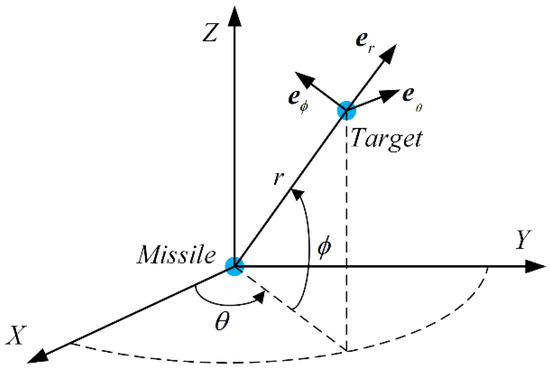
Figure 1.
Three-dimension schematic diagram of missile-target engagement.
The relative velocity in LOS coordinate system V satisfies the following differential form
where ; and represent the absolute derivative of in inertial coordinate system, and the relative derivative of in LOS coordinate system, respectively; and represent the accelerations of the target and missile, respectively; and represents the relative rotation angular velocity of LOS coordinate system relative to inertial coordinate, which is given by
Substituting Equations (2) and (4) into the Equation (3), the three-dimension missile-target engagement kinematic could be described as
Remark 1.
From Equation (5), it can be observed that and are singular points. However, due to the physical shapes of the missile and target in real practice, the relative distance converges in a neighborhood of zero, which means does not occur throughout the detection and guidance process. In addition, regular points have been proven unstable in [26]. Hence, the control system just crosses these points without stay.
During the design of guidance law, desired LOS terminal angles and are always considered to be the constraint. Denoting and as the control variables, Equation (5) can be rewritten as
where
2.2. Preliminaries
Notation 1.
For any given vector , denote its absolute value as , its time derivative as , its sign function as , its second power as , and its 2-norm as . For any positive definite matrix , denote and to represent the minimum and maximum eigenvalues of , respectively, and satisfying following inequation: . In addition, denote operation symbol “” as the Hadamard product symbol, denote operation symbol “” as the Kronecker product symbol.
Assumption 1.
Assume the target accelerations and are unknown but bounded, continuous, and differentiable. Additionally, is unknown but bounded, continuous, and differentiable and is unknown but bounded and continuous. Assume the absolute values of and satisfy following inequation
where and are positive constants.
Assumption 2.
The seeker time delay is an approximate known positive constant.
Lemma 1.
For a first-order nonlinear system , . Assume there exists continuous and positive definite function satisfies the following inequality [37]
where , and are constants. Then, there exists a region such that any starting from this region can reach in a finite time , which is formulated as
where is the initial value of .
3. Measurement Compensation System for Time-Delay Seeker Based on Predictive ADRC
In this section, a seeker measurement model with lags and delays is formulated. Following this, based on predictive ADRC theory, a measurement compensation system is reconstructed, and the calculation process is given.
3.1. Modelling for Time-Delay Seeker Considering Lag Dynamics
In the process of homing missile guidance, the guidance loop needs to obtain the real-time LOS angles and LOS angular rates. Denoting and are the measured azimuth and elevation angles of the seeker, respectively. Then, considering first-order seeker dynamics and time delay, and can be formulated as
where is the time scale of the seeker dynamics and is the pure time delay of the seeker, which is an unknown but positive constant. Based on Equation (11), Figure 2a,b show the trend of LOS angles and LOS angular rates measurement, respectively, in respect to the flight time of missiles under different pure time delays.
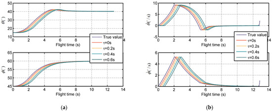
Figure 2.
The seeker measurements under different time delays: (a) The measured LOS angles with lags and delays; (b) The measured LOS angular rates with lags and delays.
For Equation (11), denoting , , and , rewrite it as
From Equation (12), one can observe that the input variable is the LOS angle without time delay and dynamics lag, which is ideal for the missile guidance system. To estimate and reconstruct the seeker measurements, the following analysis is based on S-domain for convenience. Denoting as the complex variable, the S-domain transfer function of system (12) can be formulated as
Introduce a virtual output variable which is given by
It is obvious that has no time delay, implying that if we could track its value we could eliminate the effects of time delay. Inspired by [18], this paper proposes a novel measurement reconstruction system based on tracking differentiator and active disturbance rejection control theory to track and reject disturbance.
3.2. Measurement Compensation System Design
Figure 3 shows the entire measurement reconstruction structure for the seeker. The reconstruction process can be divided into two parts:
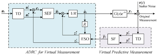
Figure 3.
The ADRC compensation structure for seeker.
- 1.
- Predictive tracking for virtual measurement
This part is formed from an optimal tracking differentiator (TD) and a state feedback (SF) controller. The discrete TD equation can be formulated as
where and are previous time mark and current time mark, respectively; is sample time; and are designed positive constants, higher leads to higher tracking speed, and higher leads to better filtering effect to the system; and are the output of TD, which tracks and , respectively; and function is given by
It can be concluded that TD in the form of Equation (15) has the property to filter noises due to its first-order differentiation loop. Then the SF controller in a classical predictor observer can be described as
However, is an approximate known constant based on Assumption 2. Thus, rewrite above equation as
where and are designed constants.
- 2.
- ADRC for virtual measurement
In the process of predictive tracking for virtual measurement , approximate delay parameters are used, which add uncertainty to the system. In addition, noises and lags occur in the seeker detection process, and disturbances also exist when has dynamic changes. To compensate lag, and reject the uncertainty and disturbances including noises, an ADRC system is introduced, which consists of three subsystems: TD, extended state observer (ESO), and state error feedback (SEF).
- Transient process based on TD
The TD is utilized to track and , which is given by
where and are the output of TD, which tracks and , respectively; function fhan is given in Equation (16).
- State and disturbance estimation based on ESO
The ESO is used to eliminate disturbances and estimate the real value of , which is formulated as
where input gain is a positive constant; error gains and are positive constants; is the observed quantity of ; is the error between the estimated and real value of ; and are the output values of the ESO, which represent the estimation of and error, respectively; and is error function, which is given by
where and are constants, which represent order and boundary of , respectively.
Remark 2.
The stabilization of ESO systems has been proven in [18], which clarified that when the observer gains are selected appropriately, the errors of the ESO could converge to neighborhood of zero in finite time.
- Input estimation based on SEF
The SEF can calculate the error between and , which is given by
where is the error feedback; is positive constant. Thus, can be formulated as
As a result, using Equations (15)–(22), the input estimation can be calculated. Meanwhile, the delayed measurement is compensated, and the LOS angle is reconstructed during the process.
Remark 3.
The reconstruction of LOS angular rate can be described by the difference of LOS angle, which is given by
where and are the estimations of azimuth and elevation angular rates at current time, respectively.
4. Adaptive Guidance Law Design Considering Terminal Angle Constraint
In this section, a fast convergent nonsingular sliding manifold variable is introduced. An adaptive sliding mode guidance law, regardless of target maneuvers and based on STA, is proposed, and the stabilization of the guidance law is studied based on Lyapunov theory.
4.1. Design of Adaptive Sliding Mode Guidance Law Based on STA
Considering both convergence speed and nonsingularity, the following sliding manifold for system (6) is proposed, which is given by
where is the sliding manifold vector; and are positive constants; and term is formulated as
where ; constants , ; and are designed to keep continuous, which satisfies
Then the time derivative of can be formulated as
where term is given by
According to Equations (15)–(23), denote
Then Substituting Equation (6) into Equation (27) and replacing , and with , and yields
where
In order to eliminate the chattering of the sliding mode control and ensure the effectiveness of the guidance law facing maneuvering target. The adaptive STA control method is utilized in this paper. On the bases of adaptive super-twisting control theory and the nonlinear sliding manifold, regarding as the system disturbance, a target-independent guidance law with adaptive gains based on STA can be formulated as
where
where , , , and are positive constants. In reference [33], to compensate the objective system uncertainty, an equivalent control variable and its error variable are introduced, which satisfies
where is a constant, satisfies ; is a positive constant; and is small and positive, which satisfies .
In Equation (34), the equivalent control variable is based on a first-order low pass filter, to filter the discontinuous injection signal , and the error variable is designed to satisfy , as . Hence, to improve the filtering performance and the convergent speed of the error variable, a novel equivalent control variable and its error variable are formulated as
where and are positive constants, and . Compared with Equation (34), the error variable in Equation (35) has a fast convergence form which can drive the value of the adaptive gain to counteract the equivalent control variable of disturbance in faster speed.
Then, the adaptive time-varying gain is given by
where is the initial value of ; is the initial value of ; and is a positive constant.
Proposition 1.
Following Equations (34)–(36), the STA adaptive gain satisfies in finite time.
Proof of Proposition 1.
See Appendix B. □
4.2. Stability Analysis of The Proposed Guidance Law
The main conclusion of this part is summarized as following theorem.
Theorem 1.
Consider the three-dimension missile-target engagement system with terminal angle constraint (Equation (6)), the proposed adaptive STA guidance law (Equation (32)) can drive the sliding surface converge to a small neighborhood around zero in finite time , if the adaptive gain factors are governed as
and is given by
where and are denoted in Equation (58).
Proof of Theorem 1.
Substituting Equation (32) into Equation (30) and replacing by yields
In order to simplify the Hadamard product operations, consider the adaptive gain as a scalar quantity form , and Equation (39) can be rewritten as
Introduce an auxiliary vector , which is formulated as
Then, the derivative of is given by
Consider following Lyapunov function candidate
where
From Equation (43), one can conclude that
Taking the derivative of into time yields
where
Denote and . Thus, can be written as
where
It can be concluded that Equations (48)–(50) satisfy
where
Then, the derivative of the Lyapunov function satisfy the following inequality
where
It can be concluded that and are positive definite matrices under condition (37). Thus, satisfy
Considering (45) and (55), the following condition holds
Substituting (51), (52) and (56) into (54) yields
where
Letting
It can be found that and are positive in finite time under Proposition 1. And based on Lemma 1, the proposed guidance law is stabilized in finite time. □
5. Simulation
In this section, several simulation situations are designed to study the effectiveness of the proposed measurement compensation system and guidance law. First, the effectiveness of the compensation system based on predictive ADRC is discussed; next, variable desired terminal angles are taken in consideration to test the performance of the proposed guidance law with the compensation system. Finally, compared with other guidance laws, the property of the proposed guidance law with measurement compensation system is demonstrated further. All the simulations are supported by MATLAB platform due to its adequate libraries and powerful matrix calculation ability. Throughout the simulations, a fourth-order Runge-Kutta solver with a fixed step size is used.
5.1. Simulation of The Predicrive ADRC Compensation System
A simulation example of missile-target engagement guidance is investigated to verify the effectiveness of the proposed predictive ADRC compensation system (Equations (15)–(23)). In addition, this example is simulated on the basis of the proposed guidance law (Equation (32)).
Since the capacity of actuator dynamics is limited in real practice, the maximum lateral acceleration is limited as follows
This paper selects throughout the simulations.
To address the discontinuity problem of the sign function sign(x), a sigmoid function is utilized to replace it during the simulation, which is formulated as
The simulation example is set up as follows: (1) the initial missile-target engagement condition: , , , , , and ; (2) the target maneuver condition: , and ; (3) the seeker parameters: , , output noise is zero-mean Gaussian white noise with power spectral density , and its variance is 0.0001 °/s considering narrow band; (4) the parameters of measurement compensation system are given in Table 1; (5) the parameters of sliding mode manifold and adaptive STA are given in Table 2; and (6) the fixed step size of the fourth-order Runge-Kutta solver is 0.001 s.

Table 1.
The parameters of measurement compensation system.
Table 2.
The parameters of sliding mode manifold and adaptive STA.
The simulation results are illustrated in Figure 4. Figure 4a,c show the LOS angle and LOS angular rate estimations of predictive ADRC compensation system, respectively. The estimation could track the true value calculated by the missile-target engagement dynamics in the overall guidance process. The original value detected by the time-delay seeker is also given as a comparison. Moreover, the errors between them are shown in Figure 4b,d, which illustrates the good performance of the predictive ADRC compensation system quantitively. The error ranges of LOS angles and are (−0.5° to −0.1°) and (−0.2° to −0.2°), respectively, and that of LOS angular rates and are (−0.4 °/s to 0.2 °/s) and (−0.1 °/s to −0.1 °/s), respectively.
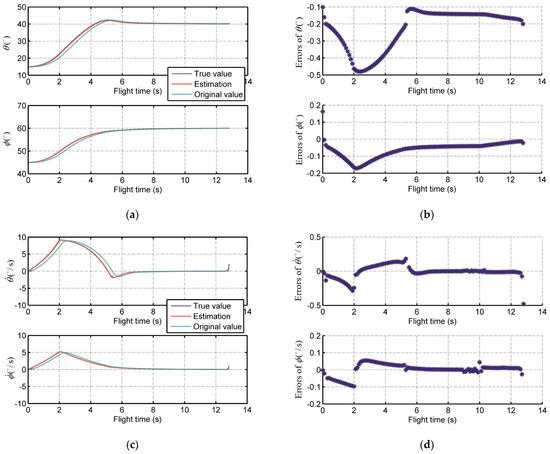
Figure 4.
The performance of the proposed predictive ADRC compensation system for seeker lag and time delay: (a) True value, estimation, and original value of LOS angle; (b) Errors between true value and estimation of LOS angle; (c) True value, estimation, and original value of LOS angular rate; (d) Errors between true value and estimation of LOS angular rate.
Figure 5 shows the Monte Carlo simulation result, where the single scatter point represents the average value of the errors between estimation values and true values during the entire flight time in one Monte Carlo run. Excluding a few large error scatters, the range of the error mean value can be governed. The mean value error ranges of LOS angles and are (−0.6° to 0°) and (−0.3° to 0.1°), respectively, and that of LOS angular rates and are (−0.015 °/s to 0.006 °/s) and (−0.015 °/s to −0.004 °/s), respectively. Those small errors demonstrate the strong property of robustness of the proposed predictive ADRC compensation system.
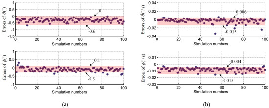
Figure 5.
The Monte Carlo simulation result of the errors: (a) The LOS angle errors in 100-times simulation; (b) The LOS angular rate errors in 100-times simulation.
5.2. Simulation of Different Terminal Angle Constraints
In order to test the terminal angle constraint properties of the proposed guidance law with the ADRC predictor observer, a simulation example of missile-target engagement guidance is investigated. The missile is expected to hit the target in the desired terminal angles: = 70°, 60°, 50°, 30°, and 20°, when = 45°; = 45°, 30°, 20°, 0°, and −15°, when = 15°. Other initial conditions and system parameters are the same as in Section 5.1.
The simulation results are illustrated in Figure 6 and Figure 7. Figure 6a and Figure 7a show the trajectories of missile target relative distances in the inertial coordinate system when = 45° and = 15°. We see that all the trajectories converge to zero, which implies that the missile can catch up with the target in finite time without obtaining target acceleration information. Figure 6b and Figure 7b show the trend of LOS angle over flight time in the two conditions. In this sample, the LOS angles and can reach the desired terminal angle within 7 s and 10 s, respectively, and then maintain it. This phenomenon verifies the terminal angle and seeker delay constraint properties of the proposed guidance law. Moreover, the convergence time and flight time are subject to the difference between the initial LOS angle and desired terminal angle. Larger gaps could lead to longer trajectories and longer convergence time.
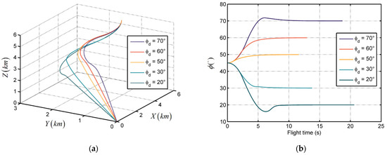
Figure 6.
The performance of the proposed guidance law with different desired terminal azimuth angles: (a) Relative distance trajectories; and (b) LOS angles.
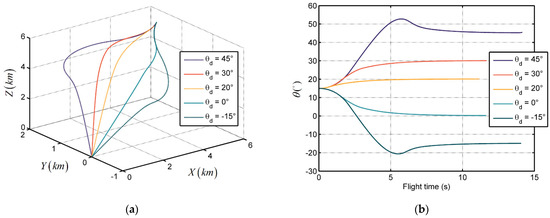
Figure 7.
The performance of the proposed guidance law with different desired terminal elevation angles: (a) Relative distance trajectories; and (b) LOS angles.
5.3. Compared with Other Guidance Laws
The fixed-gain STA-based sliding mode control (STASMC) guidance law and fast convergent terminal sliding mode (TSM) guidance law are introduced for comparison. The fixed-gain STASMC guidance law is formulated as [35]
This paper selects the parameters of (62) as , , , and .
The TSM guidance law is given by [28]
This paper selects the parameters of (62) as , , and , and assumes the target acceleration is known for ease.
To further verify the applicability and robustness of the proposed guidance law and the proposed predictive ADRC compensation system, three kinds of scenarios with various measurement and target maneuvers are taken into account:
- The seeker measurement is ideal, which has no delays or noises. The target accelerations in LOS coordinate is given by ;
- The seeker measurement is ideal, which has no delays or noises. The target accelerations in LOS coordinate is given by ;
- The seeker measurement has delays and noises, which are given by , , . The target accelerations in LOS coordinate is given by .
Besides the above, the initial conditions and parameters of these three scenarios are as same as that in Section 5.1.
The comparison results of scenarios 1 and 2 are shown in Figure 8 and Figure 9, respectively. Figure 8a and Figure 9a illustrate the relative distance trajectories, and all the three guidance laws converge to zero. In Figure 8b and Figure 9b, one can observe that the acceleration output of the proposed guidance law is continuous and smooth. Contrarily, the accelerations of STASMC and TSM chatter significantly. The LOS angle curves in Figure 8c and Figure 9c and the LOS angular rate curves in Figure 8d and Figure 9d depict the terminal angle constrained property of the guidance laws. The LOS angles of these three conditions can reach the desired terminal angle and the LOS angle rates can converge to zero. Figure 8e and Figure 9e show the trend of the adaptive STA gains of the proposed guidance law, which are bounded during flight time. The sliding variables of the proposed scenarios reach zero at approximately 6 s and 5 s, respectively, as shown in Figure 8f and Figure 9f.
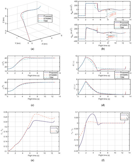
Figure 8.
Comparison results of scenario 1: (a) Relative distance trajectories; (b) Output accelerations of guidance loops; (c) LOS angles; (d) LOS angular rates; (e) The adaptive STA gains; and (f) The sliding manifold.
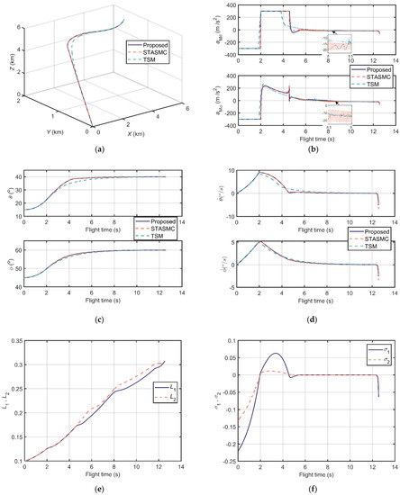
Figure 9.
Comparison results of scenario 2: (a) Relative distance trajectories; (b) Output accelerations of guidance loops; (c) LOS angles; (d) LOS angular rates; (e) The adaptive STA gains; (f) The sliding manifold.
Moreover, other information including flight time, miss distance, settling time (±0.5°), and error of LOS angles is listed in Table 3 and Table 4. Miss distance states the distance between missile and target at the end. Settling time (±0.5°) indicates the time that LOS angles reach the ±0.5° neighborhood of the desired terminal angles and then maintain it. Error of θ and error of ϕ are errors between simulation terminal angles and desired terminal angles. From Table 3 and Table 4, one can conclude that the proposed guidance law has a superior performance in miss distance, settling time (±0.5°), and terminal LOS angle errors in these two designed scenarios.
Table 3.
Simulation results of scenario 1.
Table 4.
Simulation results of scenario 2.
Unlike Figure 8 and Figure 9, the comparison results of scenario 3 in Figure 10 take the proposed compensation system in account as well. Figure 10a is the relative distance trajectories of the proposed guidance law with the proposed compensation system and the three guidance laws without measurement compensation structures. It is obvious that the trajectories of those without compensation have distinct chattering, and are longer than those proposed with a compensation system. The chattering also occurs in the aspects of output accelerations, LOS angles, and LOS angular rates, as shown in Figure 10b, Figure 10c and Figure 10d, respectively. The chattering phenomenon is caused by the additional seeker lag, measurement delay, and noise. Due to this reason, the LOS angle and LOS angular rate curves of these three guidance laws do not converge. On the other hand, due to the compensation property of the proposed compensation system for lags, delays, and noises, the curves of the proposed guidance law with compensation system are smooth and stable in Figure 10b–d.
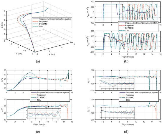
Figure 10.
Comparison results of scenario 3: (a) Relative distance trajectories; (b) Output accelerations of guidance loops; (c) LOS angles; and (d) LOS angular rates.
Similarly, the information about flight time, miss distance, settling time (±0.5°), and LOS angle error is listed in Table 5. We can observe that the proposed guidance law with compensation has the best performance in all aspects in this scenario. It should be noted that the settling time and LOS angle error of the proposed guidance law, STASMC, and TSM are not available due to their divergent LOS angles. Moreover, compared with the property of the proposed of scenario 1 listed in Table 3, the proposed with compensation maintains broadly stable flight times and miss distances, but have a slightly decreasing performance in settling time and LOS angle error.
Table 5.
Simulation results of scenario 3.
As a result, compared with STASMC and TSM, the proposed guidance law has no output chattering, less terminal LOS angle settling time, and error. In addition, the system which consists of the proposed guidance law and the proposed ADRC compensation structure has excellent seeker lag, delay, and noise constraint property and robustness.
6. Conclusions
In order to address the lag and delay problems of the seeker measurement, this paper presents a novel measurement compensation system for tactical missiles. Moreover, this paper presents a novel adaptive guidance law regardless of target maneuvers which has fast convergent gains. The simulation results demonstrate the strong disturbance rejection and accuracy property of the proposed compensation system. Also, the simulations verify the effectiveness and robustness of the proposed guidance law.
Specifically, the details of the proposed method can be summarized as follows:
- The measurement compensation system has a predictive ADRC structure, which consists of a predictive tracking loop and an ADRC loop. The predictive tracking loop could follow a virtual measurement without lags and delays. The ADRC loop ensures the tracking process stable under disturbances;
- The sliding mode guidance law is based on adaptive STA control. In order to speed the convergence of the gain error, a fast convergent error form is proposed implementing the equivalent control method to design adaptive gains. In addition, the control system is proofed for finite time convergence.
Author Contributions
Conceptualization, Y.L., G.H. and Z.Q.; methodology, Y.L.; software, Y.L.; validation, G.H., Z.G. and Z.W.; formal analysis, Y.L., Z.G. and Z.W.; investigation, Z.G. and Z.W.; resources, G.H.; data curation, G.H. and Z.Q.; writing—original draft preparation, Y.L., Z.G. and Z.W.; writing—review and editing, Y.L., G.H. and Z.Q.; visualization, Y.L.; supervision, G.H.; project administration, G.H. and Z.Q.; and funding acquisition, G.H. and Z.Q. All authors have read and agreed to the published version of the manuscript.
Funding
This research was funded by Science and Technology Commission, China Central Military Commission, grant number 2020-JCJQ-JJ-034.
Institutional Review Board Statement
Not applicable.
Informed Consent Statement
Not applicable.
Data Availability Statement
The data presented in this study are available on request from the corresponding author.
Conflicts of Interest
The authors declare no conflict of interest.
Appendix A
Table A1.
The list of acronyms used in the paper.
Table A1.
The list of acronyms used in the paper.
| Acronym | Full Name |
|---|---|
| ADRC | active disturbance rejection control |
| SMC | sliding mode control |
| LOS | Line-of-sight |
| STA | super-twisting algorithm |
| TD | tracking differentiator |
| SF | state feedback |
| SEF | state error feedback |
| ESO | extended state observer |
| STASMC | STA-based sliding mode control |
| TSM | terminal sliding mode |
Appendix B
Proof of Proposition 1.
Letting , and satisfying and .
Defining an auxiliary variable as
Taking the derivative of to time yields
Then,
Take following Lyapunov function
Thus, the derivative of is formulated as
One can observe that is bounded, and when , . Hence, there exists a finite time such that holds for , which can be written as
If , satisfies
This completes the proof. □
References
- Dhananjay, N.; Lum, K.-Y.; Xu, J.-X. Proportional Navigation with Delayed Line-of-Sight Rate. IEEE Trans. Contr. Syst. Technol. 2013, 21, 247–253. [Google Scholar] [CrossRef]
- Hecht, C.; Troesch, A. Predictive guidance for interceptors with time lag in acceleration. IEEE Trans. Automat. Contr. 1980, 25, 270–274. [Google Scholar] [CrossRef]
- Nicolas, L.; Camille, A.R. (Eds.) Backstepping Guidance for Missiles Modeled as Uncertain Time-Varying First-Order Systems. In Proceedings of the 2007 American Control Conference, New York, NY, USA, 11–13 July 2007; IEEE Service Center: Piscataway, NJ, USA, 2007. [Google Scholar]
- Moon, H.-B.; Ra, W.-S.; Whang, I.-H.; Kim, Y.J. Optimal guidance cut-off strategy based on closed-form PNG solution for single lag system. In Proceedings of the IECON 2011—37th Annual Conference of the IEEE Industrial Electronics Society, Melbourne, VIC, Australia, 7–10 November 2011; IEEE: Piscataway, NJ, USA, 2011; pp. 652–657. [Google Scholar]
- Lee, S.; Kim, Y. (Eds.) Design of Nonlinear Observer for Strap-down Missile Guidance law via Sliding Mode Differentiator and Extended State Observer. In Proceedings of the 2016 International Conference on Advanced Mechatronic Systems (ICAMechS), Melbourne, Australia, 30 November–3 December 2016; IEEE: Piscataway, NJ, USA, 2016. [Google Scholar]
- Gurfil, P. Robust guidance for electro-optical missiles. IEEE Trans. Aerosp. Electron. Syst. 2003, 39, 450–461. [Google Scholar] [CrossRef]
- Shima, T.; Shinar, J.; Weiss, H. New Interceptor Guidance Law Integrating Time-Varying and Estimation-Delay Models. J. Guid. Control Dyn. 2003, 26, 295–303. [Google Scholar] [CrossRef]
- Hablani, H.B. Endgame Guidance and Relative Navigation of Strategic Interceptors with Delays. J. Guid. Control Dyn. 2006, 29, 82–94. [Google Scholar] [CrossRef]
- Tang, T.; Tian, J.; Zhong, D.; Fu, C. Combining Charge Couple Devices and Rate Sensors for the Feedforward Control System of a Charge Coupled Device Tracking Loop. Sensors 2016, 16, 968. [Google Scholar] [CrossRef] [PubMed]
- Nikfetrat, A.; Esfanjani, R.M. Self-tuning Kalman filter for compensation of transmission delay and loss in line-of-sight guidance. Proc. Inst. Mech. Eng. Part. G J. Aerosp. Eng. 2019, 233, 4191–4201. [Google Scholar] [CrossRef]
- Hong, J.-H.; Park, S.-S.; Lee, C.-H.; Ryoo, C.-K. Study on Parasite Effect with Strapdown Seeker in Consideration of Time Delay. J. Guid. Control Dyn. 2019, 42, 1383–1392. [Google Scholar] [CrossRef]
- Ahi, B.; Haeri, M. A high-performance guidance filter scheme with exact dynamic modeling of a pitch-yaw gimballed seeker mechanism. Mech. Syst. Signal. Process. 2020, 144, 106857. [Google Scholar] [CrossRef]
- Holloway, J.; Krstic, M. Predictor Observers for Proportional Navigation Systems Subjected to Seeker Delay. IEEE Trans. Contr. Syst. Technol. 2016, 24, 2002–2015. [Google Scholar] [CrossRef]
- Coutinho, C.L.; Oliveira, T.R.; Cunha, J.P.V.S. Output-feedback sliding-mode control via cascade observers for global stabilisation of a class of nonlinear systems with output time delay. Int. J. Control 2014, 57, 1–11. [Google Scholar] [CrossRef]
- Marques, I.O.; Oliveira, T.R.; Cunha, J.P.V.S. Cascade observers for output-feedback control under parametric uncertainties, disturbances and arbitrary sensor delays. Int. J. Control 2020, 93, 2245–2256. [Google Scholar] [CrossRef]
- Caballero-Barragán, H.; Osuna-Ibarra, L.P.; Loukianov, A.G.; Plestan, F. Sliding mode predictive control of linear uncertain systems with delays. Automatica 2018, 94, 409–415. [Google Scholar] [CrossRef]
- Dev, A.; Léchappé, V.; Sarkar, M.K. Prediction-based super twisting sliding mode load frequency control for multi-area interconnected power systems with state and input time delays using disturbance observer. Int. J. Control 2019, 7, 1–14. [Google Scholar] [CrossRef]
- Han, J. From PID to Active Disturbance Rejection Control. IEEE Trans. Ind. Electron. 2009, 56, 900–906. [Google Scholar] [CrossRef]
- Zhao, S.; Gao, Z. Modified active disturbance rejection control for time-delay systems. ISA Trans. 2014, 53, 882–888. [Google Scholar] [CrossRef] [PubMed]
- Zheng, Q.; Gao, Z. Predictive active disturbance rejection control for processes with time delay. ISA Trans. 2014, 53, 873–881. [Google Scholar] [CrossRef] [PubMed]
- Liao, X.-C.; Zhou, Y.; Chen, Z.H. Research on fast self-learning improvement of ADRC control algorithm for film thickness control system. J. Phys. Conf. Ser. 2019, 1187, 32024. [Google Scholar]
- Zhang, B.; Tan, W.; Li, J. Tuning of Smith predictor based generalized ADRC for time-delayed processes via IMC. ISA Trans. 2020, 99, 159–166. [Google Scholar] [CrossRef] [PubMed]
- Huba, M.; Oliveira, P.M.; Bistak, P.; Vrancic, D.; Žáková, K. A Set of Active Disturbance Rejection Controllers Based on Integrator plus Dead-Time Models. Appl. Sci. 2021, 11, 1671. [Google Scholar] [CrossRef]
- Che, X.; Tian, D.; Jia, P.; Gao, Y.; Ren, Y. Terminal Sliding Mode Control with a Novel Reaching Law and Sliding Mode Disturbance Observer for Inertial Stabilization Imaging Sensor. Sensors 2020, 20, 3107. [Google Scholar] [CrossRef]
- Tan, J.; Fan, Y.; Yan, P.; Wang, C.; Feng, H. Sliding Mode Fault Tolerant Control for Unmanned Aerial Vehicle with Sensor and Actuator Faults. Sensors 2019, 19, 643. [Google Scholar] [CrossRef] [PubMed]
- Kumar, S.R.; Rao, S.; Ghose, D. Nonsingular Terminal Sliding Mode Guidance with Impact Angle Constraints. J. Guid. Control Dyn. 2014, 37, 1114–1130. [Google Scholar] [CrossRef]
- Liu, X.; Li, G. Adaptive Sliding Mode Guidance with Impact Time and Angle Constraints. IEEE Access 2020, 8, 26926–26932. [Google Scholar] [CrossRef]
- Ji, Y.; Lin, D.; Wang, W.; Hu, S.; Pei, P. Three-dimensional terminal angle constrained robust guidance law with autopilot lag consideration. Aerosp. Sci. Technol. 2019, 86, 160–176. [Google Scholar] [CrossRef]
- Zhang, W. An impact angle constraint integral sliding mode guidance law for maneuvering targets interception. JSEE 2020, 168–184. [Google Scholar] [CrossRef]
- Wang, X.; Qiu, X. Study on Fuzzy Neural Sliding Mode Guidance Law with Terminal Angle Constraint for Maneuvering Target. Math. Probl. Eng. 2020, 2020, 1–12. [Google Scholar] [CrossRef]
- Levant, A. Robust exact differentiation via sliding mode technique. Automatica 1998, 34, 379–384. [Google Scholar] [CrossRef]
- Shtessel, Y.B.; Moreno, J.A.; Fridman, L.M. Twisting sliding mode control with adaptation: Lyapunov design, methodology and application. Automatica 2017, 75, 229–235. [Google Scholar] [CrossRef]
- Edwards, C.; Shtessel, Y.Y. Adaptive Dual Layer Super-Twisting Control and Observation. Int. J. Control 2016, 89, 1759–1766. [Google Scholar] [CrossRef]
- Obeid, H.; Laghrouche, S.; Fridman, L.; Chitour, Y.; Harmouche, M. Barrier Function-Based Adaptive Super-Twisting Controller. IEEE Trans. Automat. Contr. 2020, 65, 4928–4933. [Google Scholar] [CrossRef]
- Wang, W.; Ji, Y.; Lin, D.; Shi, Z.; Lin, S. A novel approximate finite-time convergent guidance law with actuator fault. Clust. Comput. 2019, 22, 10095–10107. [Google Scholar] [CrossRef]
- Ma, Q.; Ji, Y.; Niu, Z.; Gou, Q.; Zhao, L. Impact Angle Constraint Dual-Layer Adaptive Guidance Law With Actuator Faults. IEEE Access 2020, 8, 115823–115836. [Google Scholar] [CrossRef]
- Yu, S.; Yu, X.; Shirinzadeh, B.; Man, Z. Continuous finite-time control for robotic manipulators with terminal sliding mode. Automatica 2005, 41, 1957–1964. [Google Scholar] [CrossRef]


Publisher’s Note: MDPI stays neutral with regard to jurisdictional claims in published maps and institutional affiliations. |
© 2021 by the authors. Licensee MDPI, Basel, Switzerland. This article is an open access article distributed under the terms and conditions of the Creative Commons Attribution (CC BY) license (https://creativecommons.org/licenses/by/4.0/).