Design, Implementation and Practical Evaluation of an IoT Home Automation System for Fog Computing Applications Based on MQTT and ZigBee-WiFi Sensor Nodes


Abstract
1. Introduction
2. Related Work
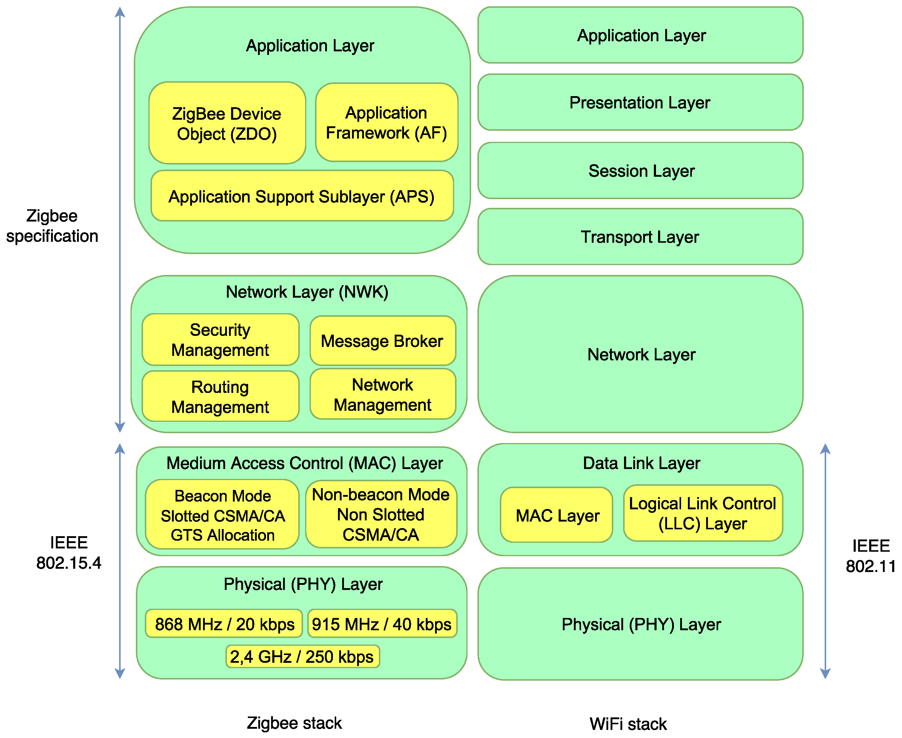
2.1. Home Automation Protocols and Technologies
2.2. Academic Solutions
2.2.1. Home Automation Systems for Heterogeneous Networks
2.2.2. Fog Computing Architectures and Applications
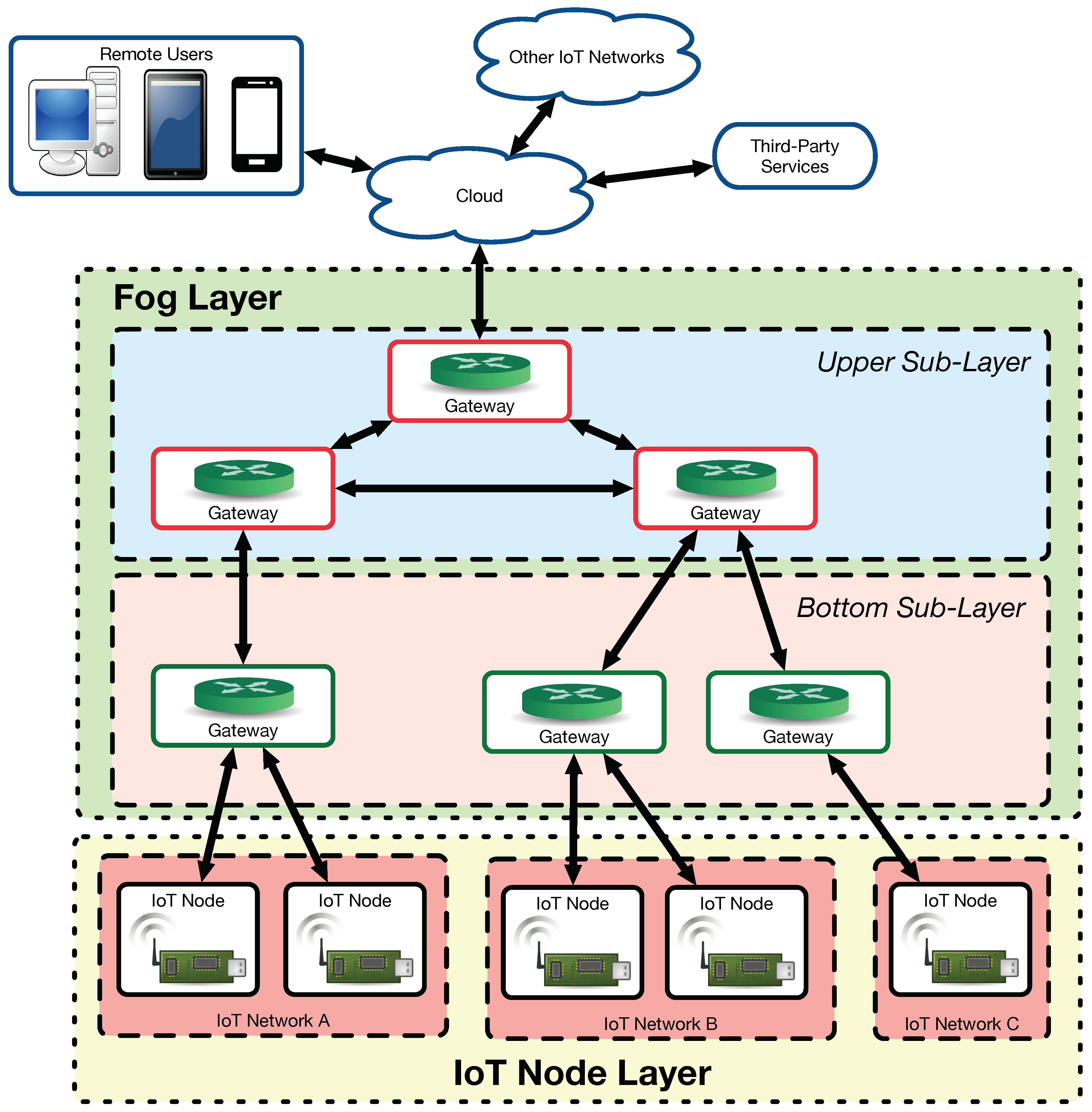
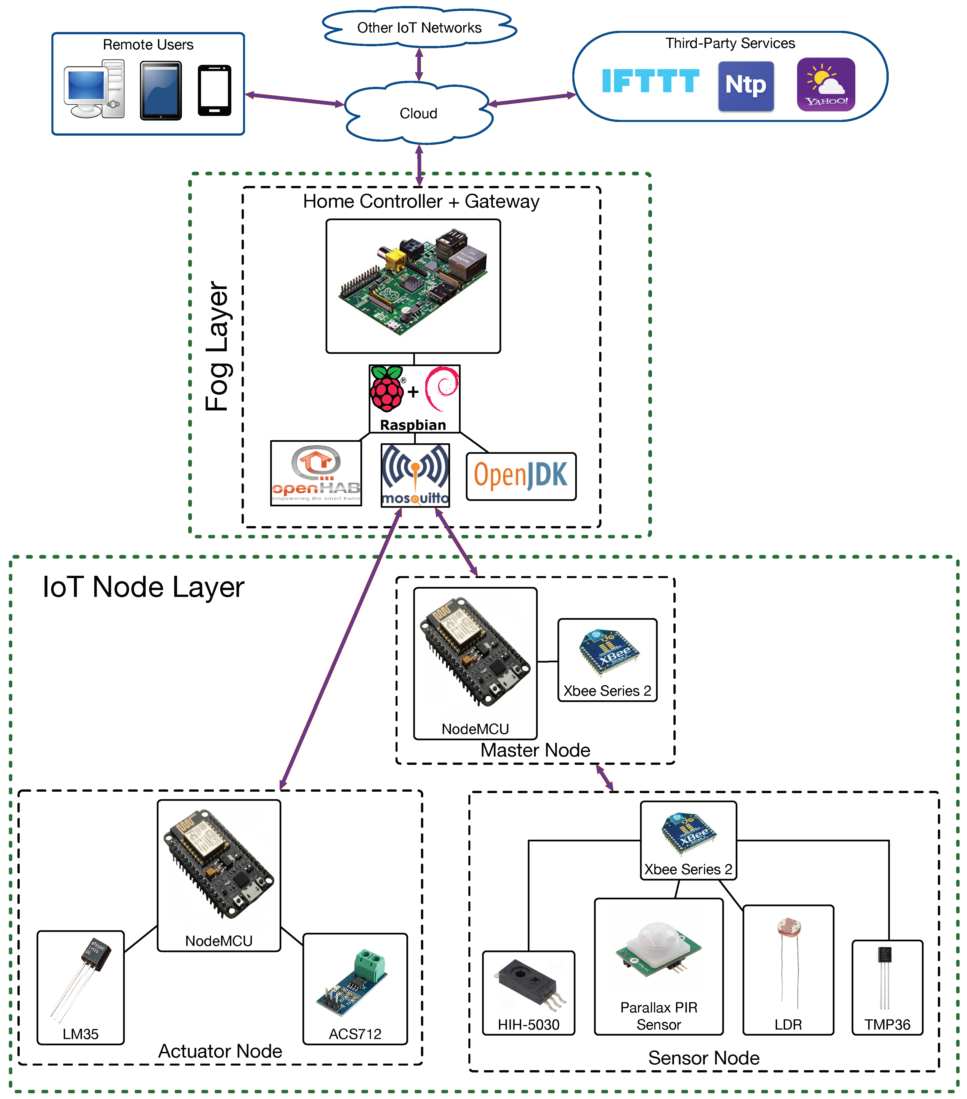
- Generic three-tier architecture [56]: it is one of the most widely used in fog computing. It consists of an IoT node layer, a fog layer and a cloud server.
- Layered approach [57]: it consists of six layers (physical/virtualization, monitoring, pre-processing, temporary storage, security and transport layers).
- Combined fog-cloud architecture [58]: it is used when there is a different storage and computing capacity in the fog nodes. It is detailed later, since it was the fog architecture selected for implementing ZiWi.
- Virtualized fog data centers [59]: this architecture enables adding multiple virtualized edge data centers to offload services from traditionally massive data centers.
2.2.3. Protocol Compatibility Approaches
2.3. Commercial Home Automation Solutions
2.4. Open-Source Home Automation Software
2.5. Analysis of the State-of-the-Art
3. System Design
3.1. HAS Architecture
3.2. IoT Nodes
- XBee Series 1. They are mainly used for point-to-point communications. They are the simplest to use and, in fact, they can be used without almost any prior configuration.
- XBee Series 2. This series has evolved through the last few years as its features have been improved, both at a hardware and at a firmware level. They allow for configuring the modules to create a mesh network, where three different roles are assigned to nodes, existing coordinators, routers and end-devices. End-devices collect data from sensors or receive remote information from other nodes. Routers mainly act as information relays for other nodes, but they can also collect sensor data or manage actuators. The coordinator acts as a gateway of the mesh network and gathers all the information from the sensor nodes.
- Standard or PRO version. There are few differences between a regular XBee and an XBee PRO. The main difference in hardware is that the XBee PRO is a little more complex and enables programming the module. With respect to communications, the PRO version has a longer range (according to the manufacturer, up to 1.6 km in Line of Sight (LoS) scenarios) at the expense of higher power consumption. Despite these differences, the two models can be mixed within the same network.
- Operation frequency: 868/915 MHz or 2.4 GHz. Most XBee modules operate at 2.4 GHz, but there are a few that operate in the 900 MHz Industrial, Scientific and Medical (ISM) band. The advantage of working in this latter band is that signals can go further, especially with a high gain antenna, and have greater penetration, being able to reach in some scenarios up to 24 km. However, note that, unlike most of the 2.4 GHz band, the 900 MHz band is not universal, so transmissions in such a band are not allowed in some countries. Obviously, these two models cannot be mixed on the same network.
- The manufacturer approach for the Sonoff control application (eWeLink) relies on a cloud AWS (Amazon Web Services) server, so every request goes through the cloud. Therefore, Sonoff devices cannot perform complex actions or interact with each other without an Internet connection. In addition, all the private information on the use of home devices might be collected by a third-party.
- In the last few years, several security problems were found in Sonoff devices:
- –
- The original Over-The-Air (OTA) updating mechanism can be used to update remotely the official firmware [113].
- –
- Although Sonoff devices make use of HTTPS, they do not verify SSL certificates [114], so it is straightforward to perform man-in-the-middle attacks to sniff and to alter the exchanged information.
- The firmware of the Sonoff devices is not open-source, so the user has to stick with the manufacturer features and the previously mentioned security problems. Nonetheless, some users were able to reverse-engineer certain Sonoff devices and have developed their own ESP8266 firmware [115]. Thus, such alternative firmware would allow for using Sonoff ESP8266-based devices as regular ZiWi nodes.
- Although the manufacturer provides schematics, the potential sensors to be used are limited to the ones embedded, so the devices lack flexibility when having to add new sensors or actuators.
- As of writing, there are not Sonoff products that implement the ZigBee protocol (only WiFi, GSM/GPRS and 433 MHz RF products), so their hardware would have to be adapted to be used with external ZigBee modules.
4. Implementation
4.1. IoT Nodes
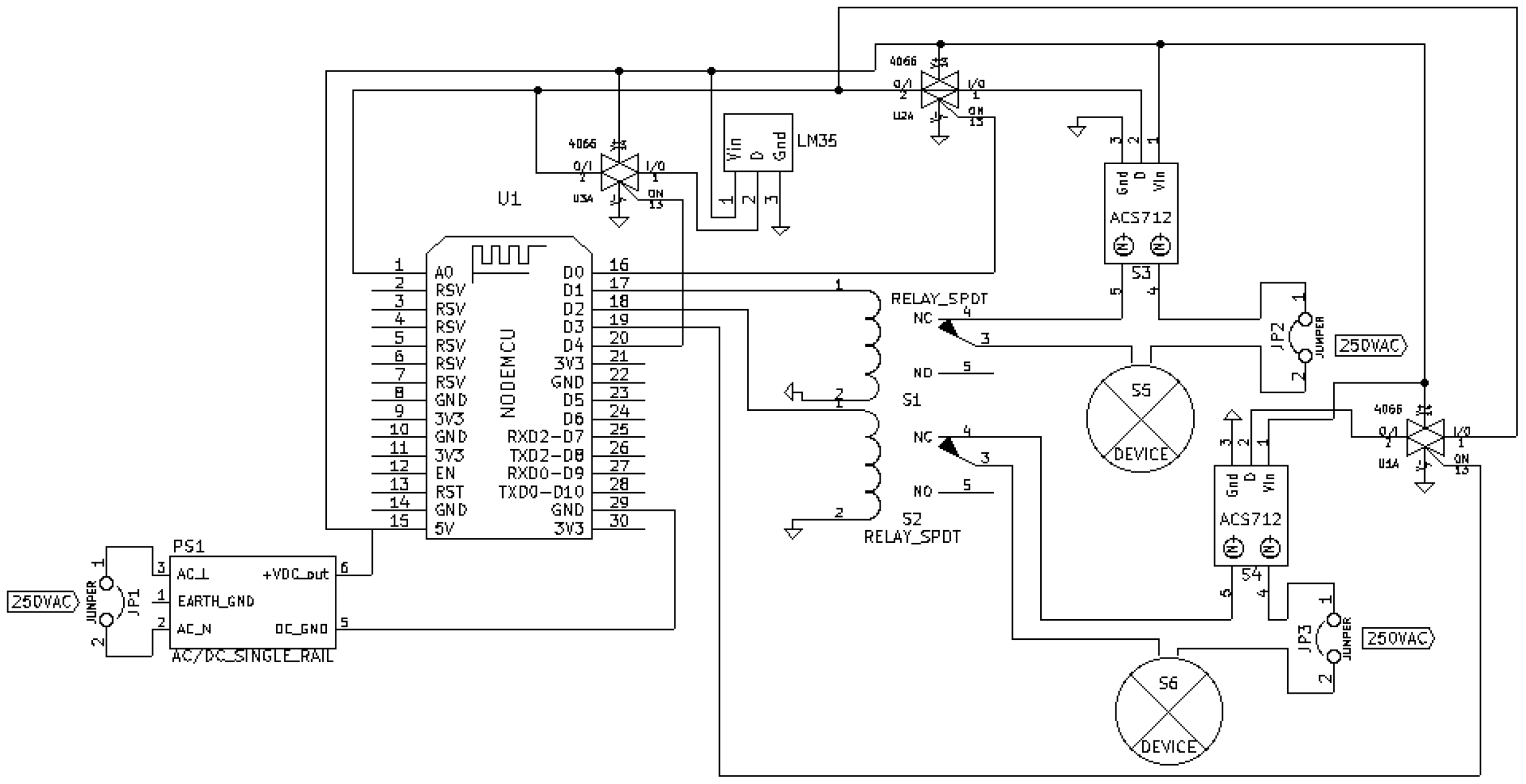
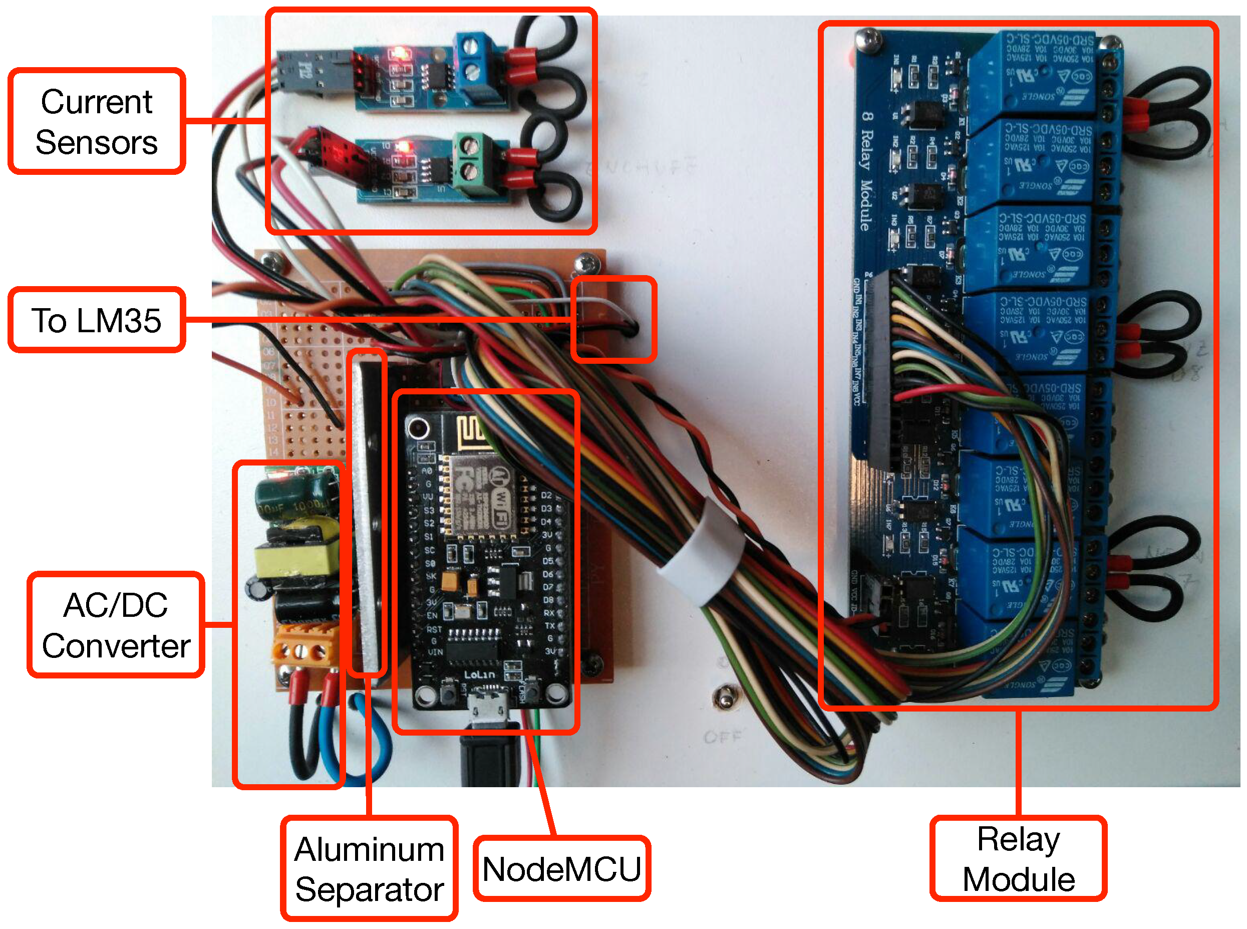
4.1.1. Actuator Nodes
- An external AC-DC converter.
- A NodeMCU.
- Two relays.
- An analog multiplexer (HCF4066BE) for choosing between the sensors that measure current (ACS172) and temperature (LM35). Note that, for the sake of clarity, instead of representing the whole integrated circuit, three of its four internal multiplexers are depicted in the schematic.
- External devices connected to the relays and to the current sensors.
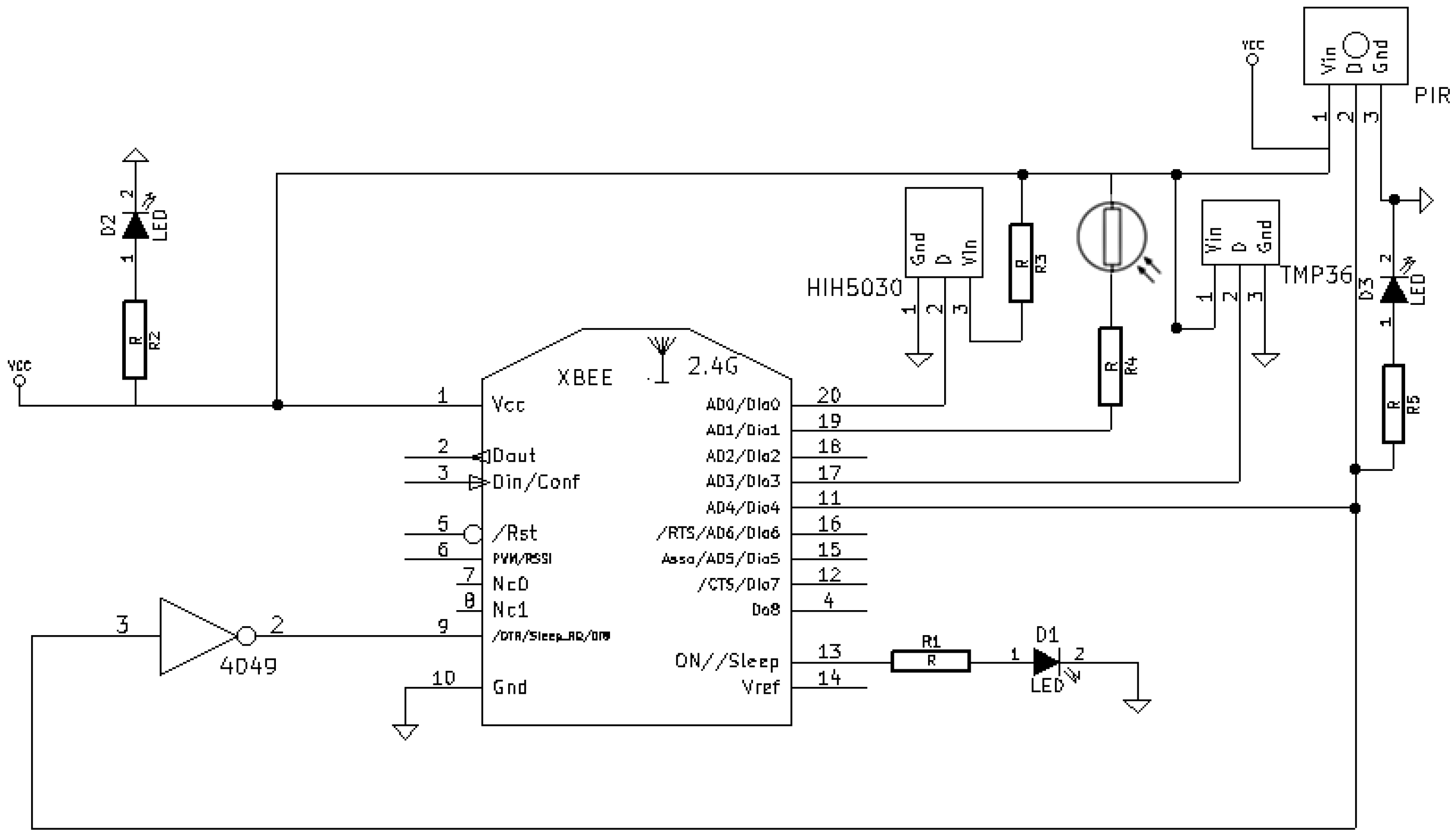
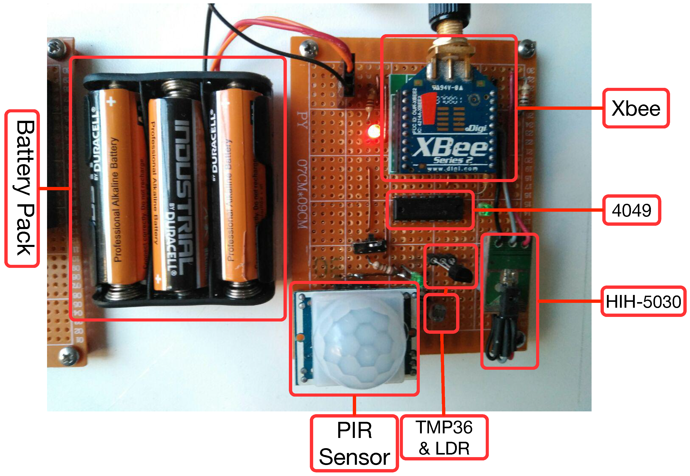
4.1.2. Sensor Nodes
- Relative humidity sensor: HIH-5030. This is an analog sensor that operates at a low voltage.
- Temperature sensor: TMP36. It provides an analog output, low consumption and enough accuracy for most home automation systems.
- Luminosity sensor: an LDR was selected due to the impossibility of using digital sensors like BH1750 or TSL2561. Note that an LDR is not as accurate as such digital sensors and that its output depends on the temperature at which it works. Nonetheless, the accuracy of the LDR is enough to distinguish between dark and bright scenarios.
- Motion sensor: a Parallax (Rocklin, CA, United States) Passive Infrared (PIR) sensor was chosen. This sensor outputs a high pulse when it detects movement and a low pulse in the opposite case. It is powered at 5 V and the logical output, which is the one that is connected to the XBee, reaches 3.3 V.
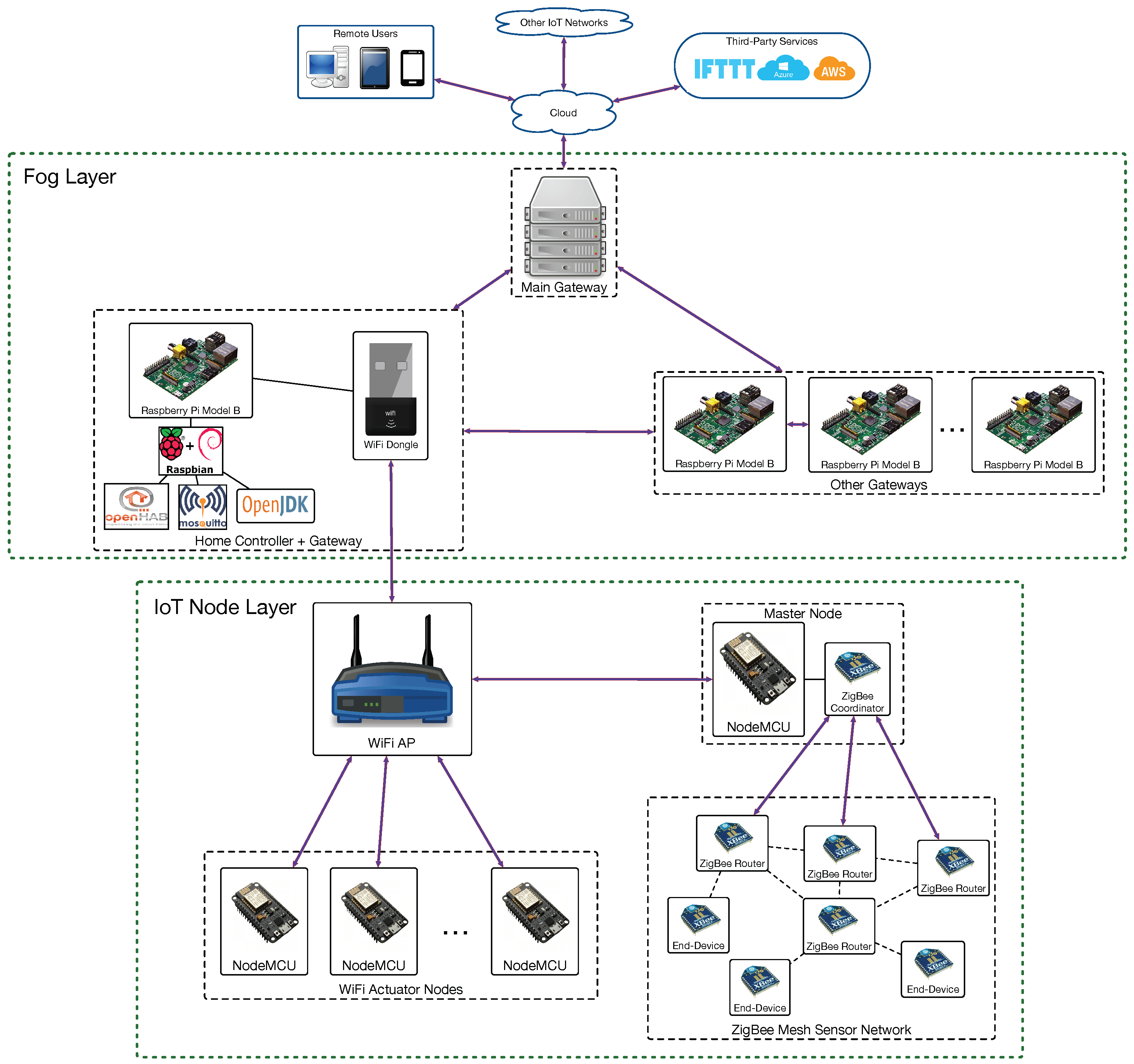
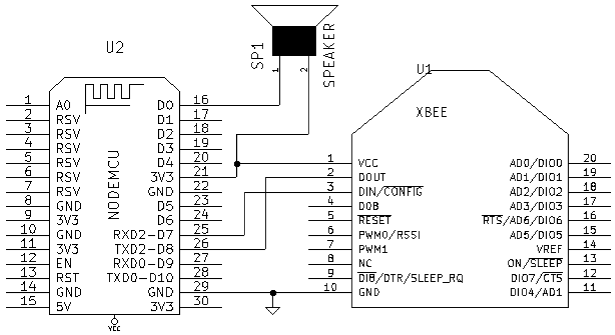
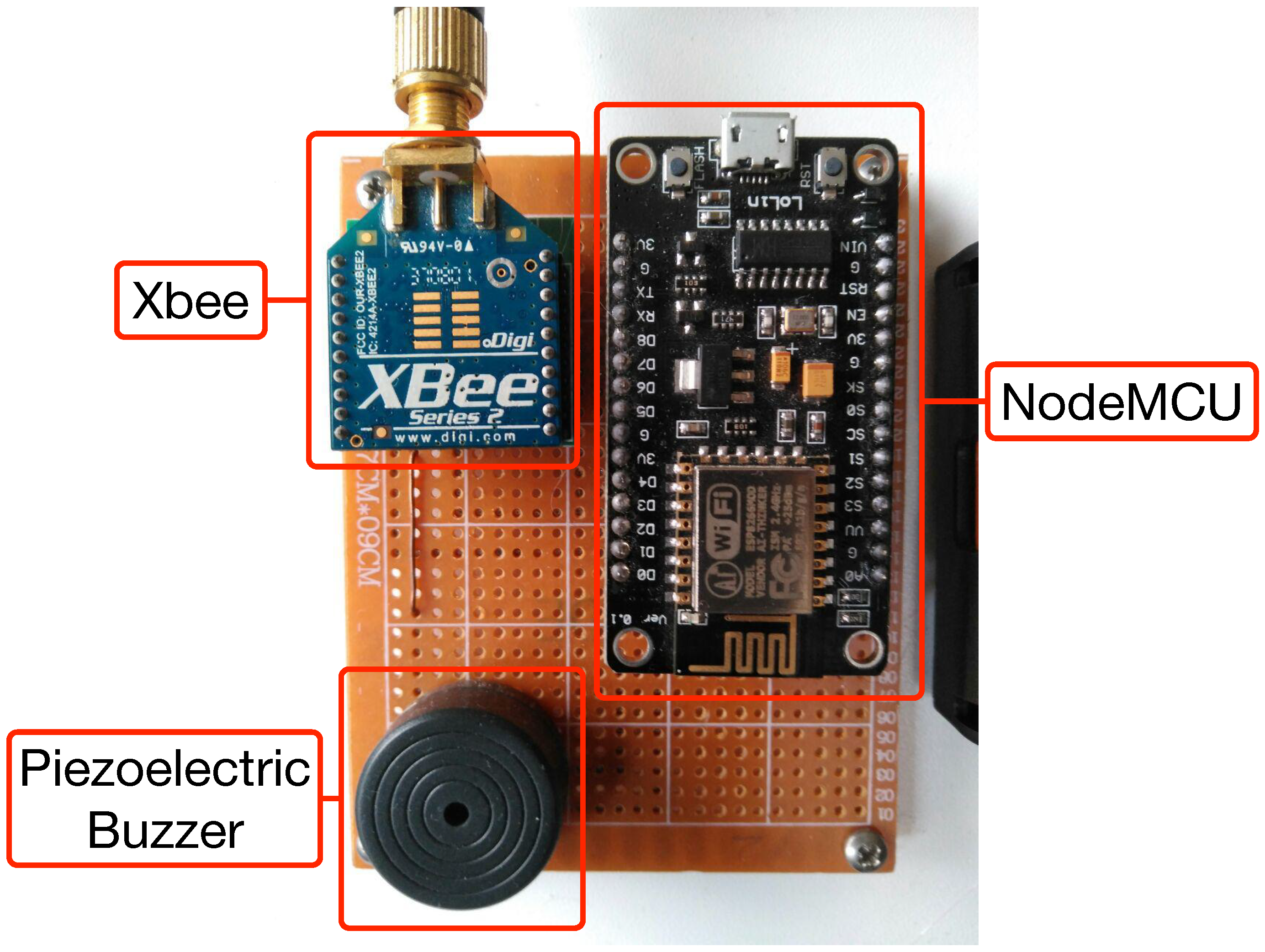
4.1.3. Master Node
- To establish a serial communication with the Xbee module that acts as ZigBee coordinator. Note that in Figure 10 the pins RXD2 and TXD2 of the NodeMCU are used because RXD0 and TXD0 are dedicated to the serial connection of the NodeMCU with the USB. The frames received from the ZigBee network consist of several bytes that include information regarding different ZigBee fields. For example, a ZigBee frame generated by a node that collects data from a sensor connected to a single ADC input would be:
 where is the start delimiter, indicate the length of the payload (that is 18 in decimal and it does not include the checksum), is the frame type (in this case, IO Data Sample RX Indicator), is the 64-bit source address, is the 16-bit source address, indicates the receive options, is the number of samples collected from the ADC, is the digital channel mask, is the analog channel mask, is the actual value read from the ADC, and is the checksum.
 - Once the ZigBee frame is processed and the sensor data are extracted, it is necessary to convert them into the appropriate magnitude, a process that is specific for every kind of sensor.

4.2. Home Controller (Main Local Gateway)
- It can run on any device capable of using a Java Virtual Machine (JVM).
- It supports a really large number of technologies, so the number of potential devices to be integrated and combined to carry out home tasks is huge.
- A growing community provides support to many ARM-based SBCs (e.g., Banana Pi, ODROID, Cubieboard...), while other platforms are focused almost exclusively on the different versions of the popular Raspberry Pi.
- It is designed to be completely vendor- and platform-neutral, without the need for using specific hardware or protocols.
- It has a powerful rule engine.
- It offers a flexible web-based user interface for PCs and mobile devices with different types of interfaces for managing dashboards, reports, configurations and performance benchmarks.
- It provides APIs for the integration of systems that are easily extensible, enabling the addition of new systems and devices.
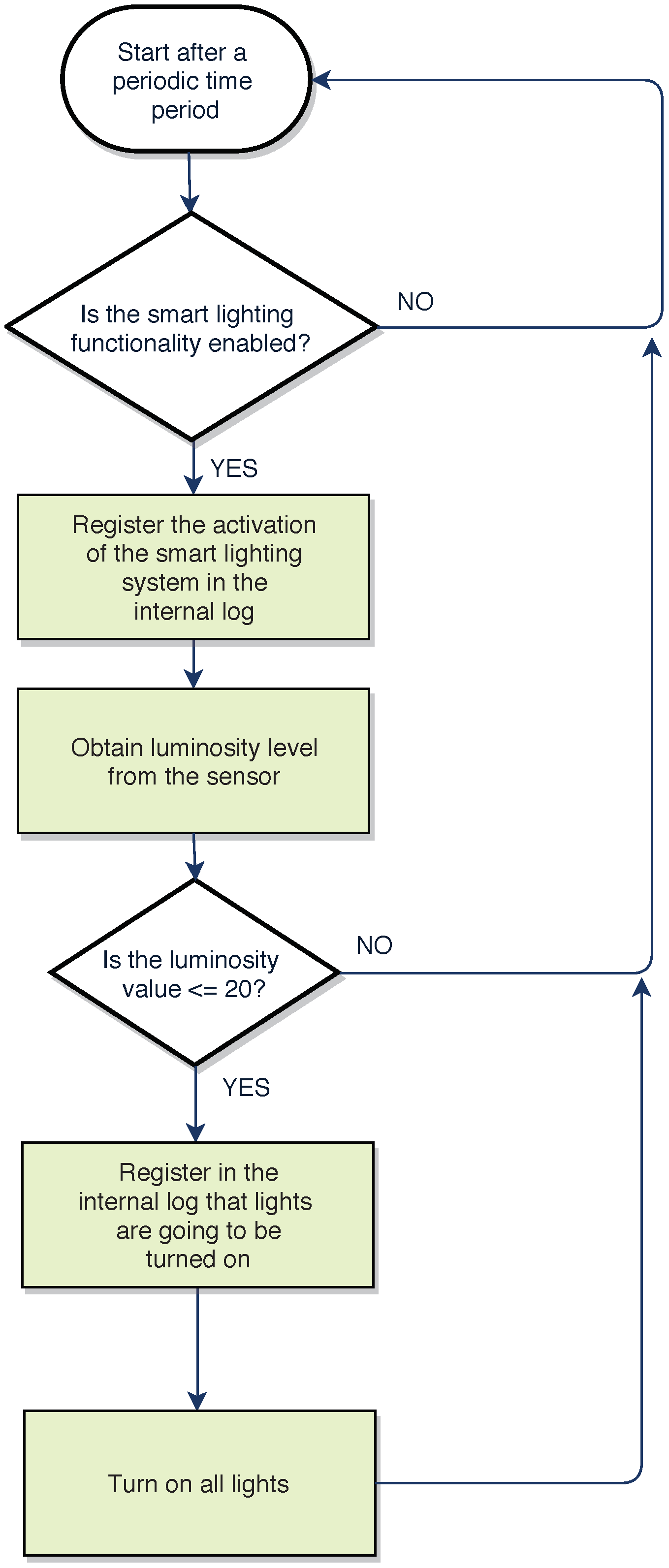
- Lighting was configured intelligently by making use of the luminosity sensors.
- Heating was switched on or off depending on indoor ambient temperature.
- Telegram notifications were sent when certain actuators changed their state.

5. Experiments
5.1. Initial Configuration
- Temperature sensors. Ideally, they should be calibrated with an industrial temperature thermometer. It is not necessary to calibrate the whole operating range, but the temperature curve between 10 °C and 30 °C should be obtained and corrected for the installed temperature sensors, since the most common values in an HAS occur in such a range.
- Relative humidity sensors. They are calibrated like temperature sensors, by using a calibrated industrial instrument. In this case, the values between 50% and 80% should be as accurate as possible, since they are the most common in comfortable homes.
- Luminosity sensor (LDR). The accuracy of this sensor is conditioned by the operating temperature (manufacturers usually only include in the datasheet curves for a temperature of roughly 25 °C). However, since the objective of this sensor is to obtain a coarse estimation of the level of clarity or darkness, a fine calibration is not necessary. Therefore, to verify the correct operation of the sensor it suffices to check the sensor under a very low light and observe that the voltage decreases clearly. In addition, the sensors should be verified when exposed to direct light, when voltage should increase.
- Movement sensor (PIR sensor). This sensor is digital and its measurement procedure is straightforward: it outputs a high pulse when movement is detected and a low pulse when it is not. Nevertheless, it is possible to calibrate its two potentiometers: one of them adjusts the distance and the detection angle, while the other one indicates the triggering time when it detects movement (i.e., the time during which the sensor outputs a high pulse after detecting a movement, which in many scenarios should be low enough to detect two consecutive movements in a short period of time).
- Current sensor. To calibrate this sensor, it is necessary to determine the value of the voltage read when there is no current flowing. This is determined by using a high precision voltmeter. In addition, the actual consumed power was calibrated with commercial appliances (a 75 W light bulb and a 900 W hair dryer) when operating them at maximum power and then determining any possible offset.
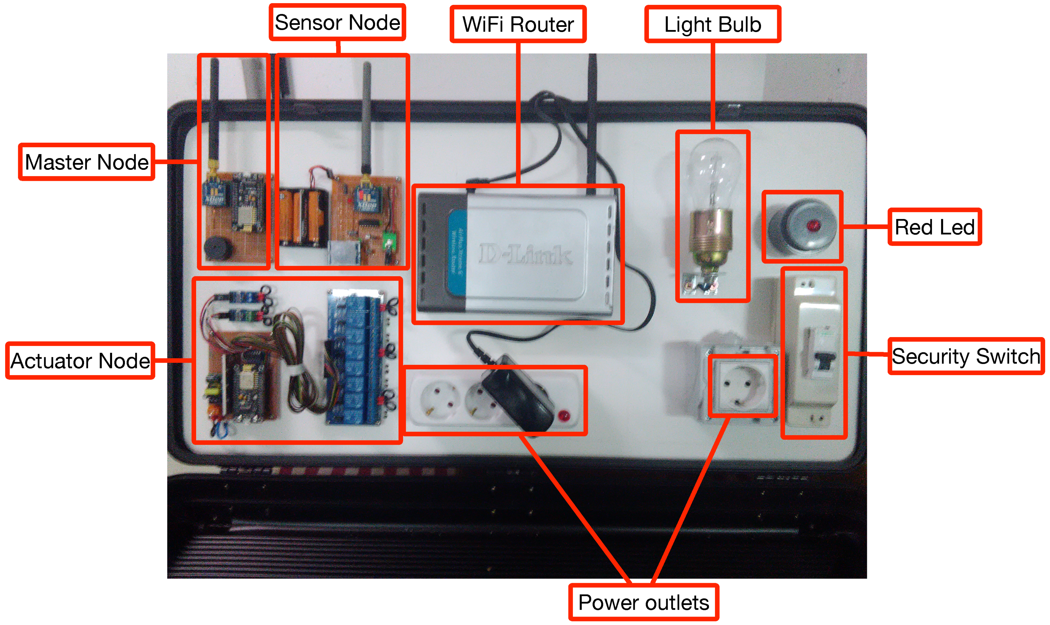
5.2. Demo Prototype
- Sensor, actuator and Master nodes.
- A home controller (it is not shown in Figure 14).
- A WiFi router.
- A security switch to turn on and off all the elements of the system together.
- Several power outlets.
- A 75 W light bulb and a large red LED.
- Multiple LED lights to simulate the activation and deactivation of different elements.
5.3. Response Time for Actuators and Events
5.4. Cross-Interference Evaluation
5.5. Current Consumption with Encryption
5.6. Key Findings
- The use of open-source software and COTS parts is essential to guarantee that the HAS can be replicated by third-parties. This is a key advantage over other academic and commercial systems, which are based on proprietary hardware or software, thus making it difficult to corroborate the obtained experimental results.
- Since ZiWi was conceived from scratch to be implemented on a fog computing architecture, it is really easy to scale it by only adding gateways. This usually occurs in two situations: when the number of home devices is too large to be handled by a single gateway, or when the wireless range provided by the fog gateways is not enough to cover the whole home or building. In such situations, fog gateways provide service redundancy and are able to communicate among them to route the data to the cloud.
- The use of OpenHAB resulted in an HAS that is really easy to manage through an attractive GUI and that is able to use a great deal of plugins to automatize many home automation tasks.
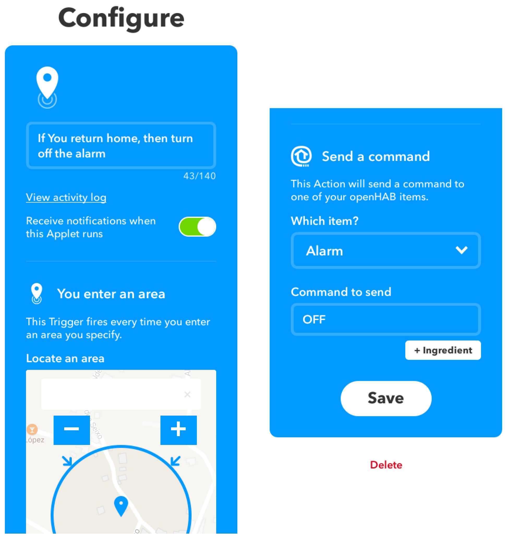
- The use of IFTTT makes it easy to connect the multiple devices deployed throughout a home, thus being able to automate the detection the relevant events and making it ideal for context-aware applications.
- The proposed system is able to decouple the hardware and software from the cloud, which reduces latencies remarkably, especially for real or quasi-real time applications (e.g., when opening doors or turning on certain appliances).
- The use of fog gateways offloads a relevant number of tasks from the cloud and also increases security. Such a security is essential for preserving the privacy of the user data, which do not have to be sent to the cloud and that do not have to be stored in servers maintained (and secured) by third-parties. In addition, device access and data availability depend mostly on fog gateways, so the communication blackouts that occur in the cloud have a limited impact on the HAS.
- The use of MQTT enables addressing most of the compatibility issues associated with the diversity of protocols, technologies and standards that exist in the field of home automation. In addition, MQTT consumes very few computational resources, so it can be implemented on resource-constrained devices.
- ZigBee-WiFi cross-interference can be problematic in environments where a lot of data are exchanged, but, in most home networks, under regular use of the communication resources, although packets can become corrupted, most of them should arrive correctly. Nonetheless, a careful frequency planning is recommended to minimize interference.
- The cost of the whole demonstrator (indicated in Table 2) is less than 20% of the cost of a basic commercial system (around €1000). Therefore, ZiWi not only is able to add numerous features, but also opens the field of home automation to many people that cannot afford costly commercial solutions.
6. Conclusions
Author Contributions
Funding
Conflicts of Interest
Abbreviations
| ADC | Analog-to-Digital Converter |
| AMQP | Advanced Message Queuing Protocol |
| AP | Access Point |
| API | Application Programming Interface |
| APS | Application Support Sublayer |
| BLE | Bluetooth Low Energy |
| HAS | Home Automation System |
| HVAC | Heating, Ventilation and Air-Conditioning |
| IoT | Internet of Things |
| IPSP | Internet Protocol Support Profile |
| ISM | Industrial, Scientific and Medical |
| JMS | Java Messaging Service |
| JVM | Java Virtual Machine |
| MOM | Message-Oriented Middleware |
| MQTT | Message Queuing Telemetry Transport |
| MOM | Message-Oriented Middleware |
| MTC | Machine-Type Communications |
| NTP | Network Time Protocol |
| RPC | Remote Procedure Call |
| SoC | System on Chip |
| SMD | Surface-Mount Device |
| SSL | Secure Sockets Layer |
| STOMP | Simple (or Streaming) Text Oriented Messaging Protocol |
| XMPP | Extensible Messaging and Presence Protocol |
| VPN | Virtual Private Network |
| 6LowPAN | IPv6 over Low-Power Wireless Personal Area Networks |
References
- Blanco-Novoa, Ó.; Fernández-Caramés, T.M.; Fraga-Lamas, P.; Vilar-Montesinos, M.A. A Practical Evaluation of Commercial Industrial Augmented Reality Systems in an Industry 4.0 Shipyard. IEEE Access 2018, 6, 8201–8218. [Google Scholar] [CrossRef]
- Fraga-Lamas, P.; Fernández-Caramés, T.M.; Blanco-Novoa, Ó.; Vilar-Montesinos, M.A. A Review on Industrial Augmented Reality Systems for the Industry 4.0 Shipyard. IEEE Access 2018, 6, 13358–13375. [Google Scholar] [CrossRef]
- Markakis, E.K.; Karras, K.; Zotos, N.; Sideris, A.; Moysiadis, T.; Corsaro, A.; Alexiou, G.; Skianis, C.; Mastorakis, G.; Mavromoustakis, C.X.; et al. EXEGESIS: Extreme Edge Resource Harvesting for a Virtualized Fog Environment. IEEE Commun. Mag. 2017, 55, 173–179. [Google Scholar] [CrossRef]
- Bonomi, F.; Milito, R.; Zhu, J.; Addepalli, S. Fog Computing and its Role in the Internet of Things. In Proceedings of the First Edition of the MCC Workshop on Mobile Cloud Computing, Helsinki, Finland, 17 August 2012; pp. 13–16. [Google Scholar]
- Fernández-Caramés, T.M.; Fraga-Lamas, P.; Suárez-Albela, M.; Díaz-Bouza, M.A. A Fog Computing Based Cyber-Physical System for the Automation of Pipe-Related Tasks in the Industry 4.0 Shipyard. Sensors 2018, 18, 1961. [Google Scholar] [CrossRef] [PubMed]
- KNX Association. Available online: http://www.knx.org (accessed on 5 July 2018).
- ISO/IEC 14908-1:2012. Information Technology Control Network Protocol, Part 1: Protocol Stack; International Organization for Standardization: Geneva, Switzerland, 2016. [Google Scholar]
- X10. Available online: https://www.x10.com/x10-home-automation.html (accessed on 5 July 2018).
- Fraga-Lamas, P.; Fernández-Caramés, T.M.; Castedo, L. Towards the Internet of Smart Trains: A Review on Industrial IoT-Connected Railways. Sensors 2017, 17, 1457. [Google Scholar] [CrossRef] [PubMed]
- Hernández-Rojas, D.L.; Fernández-Caramés, T.M.; Fraga-Lamas, P.; Escudero, C.J. Design and Practical Evaluation of a Family of Lightweight Protocols for Heterogeneous Sensing through BLE Beacons in IoT Telemetry Applications. Sensors 2018, 18, 57. [Google Scholar] [CrossRef] [PubMed]
- Hernández-Rojas, D.L.; Fernández-Caramés, T.M.; Fraga-Lamas, P.; Escudero, C.J. A Plug-and-Play Human-Centered Virtual TEDS Architecture for the Web of Things. Sensors 2018, 18, 2052. [Google Scholar] [CrossRef] [PubMed]
- Fraga-Lamas, P.; Noceda-Davila, D.; Fernández-Caramés, T.M.; Díaz-Bouza, M.; Vilar-Montesinos, M. Smart Pipe System for a Shipyard 4.0. Sensors 2016, 16, 2186. [Google Scholar] [CrossRef] [PubMed]
- Fraga-Lamas, P.; Fernández-Caramés, T.M.; Noceda-Davila, D.; Vilar-Montesinos, M. RSS Stabilization Techniques for a Real-Time Passive UHF RFID Pipe Monitoring System for Smart Shipyards. In Proceedings of the 2017 IEEE International Conference on RFID (IEEE RFID 2017), Phoenix, AZ, USA, 9–11 May 2017; pp. 161–166. [Google Scholar]
- Fraga-Lamas, P.; Fernández-Caramés, T.M.; Noceda-Davila, D.; Díaz-Bouza, M.; Vilar-Montesinos, M.; Pena-Agras, J.D.; Castedo, L. Enabling automatic event detection for the pipe workshop of the shipyard 4.0. In Proceedings of the 2017 56th FITCE Congress, Madrid, Spain, 14–16 September 2017; pp. 20–27. [Google Scholar]
- Fernández-Caramés, T.M.; Fraga-Lamas, P. A Review on Human-Centered IoT-Connected Smart Labels for the Industry 4.0. IEEE Access 2018, 6, 25939–25957. [Google Scholar] [CrossRef]
- Fraga-Lamas, P. Enabling Technologies and Cyber-Physical Systems for Mission-Critical Scenarios. Ph.D. Thesis, University of A Coruña, A Coruña, Spain, 2017. [Google Scholar]
- Fraga-Lamas, P.; Suárez-Albela, M.; Fernández-Caramés, T.M.; Castedo, L.; González-López, M. A Review on Internet of Things for Defense and Public Safety. Sensors 2016, 16, 1644. [Google Scholar] [CrossRef] [PubMed]
- Qivicon Smart Home Alliance. Available online: https://www.qivicon.com (accessed on 5 July 2018).
- Nedelcu, A.; Sandu, F.; Machedon-Pisu, M.; Aalexandru, M.; Ogrutan, P. Wireless-based Remote Monitoring and Control of Intelligent Buildings. In Proceedings of the IEEE International Workshop on Robotic and Sensors Environments, Lecco, Italy, 6–7 November 2009; pp. 47–52. [Google Scholar]
- Zamora-Izquierdo, M.A.; Santa, J.; Gómez-Skarmeta, A. An Integral and Networked Home Automation Solution for Indoor Ambient Intelligence. Pervasive Comput. 2010, 9, 67–75. [Google Scholar] [CrossRef]
- Baraka, K.; Ghobril, M.; Malek, S.; Kanj, R. Low Cost Arduino/Android-Based Energy-Efficient Home Automation System with Smart Task Scheduling. In Proceedings of the Fifth International Conference on Computational Intelligence, Communication Systems and Networks (CICSyN), Madrid, Spain, 5–7 June 2013; pp. 296–301. [Google Scholar]
- Li, Z.; Song, M.; Gao, L. Design of Smart Home System Based on ZigBee. Appl. Mech. Mater. 2014, 635–637, 1086–1089. [Google Scholar] [CrossRef]
- Cruz-Sánchez, H.; Havet, L.; Chehaider, M.; Song, Y.Q. MPIGate: A Solution to Use Heterogeneous Networks for Assisted Living Applications. In Proceedings of the 9th International Conference on Ubiquitous Intelligence and Computing and 9th International Conference on Autonomic and Trusted Computing, Fukuoka, Japan, 4–7 September 2012; pp. 104–111. [Google Scholar]
- Huang, F.L.; Tseng, S.Y. Predictable smart home system integrated with heterogeneous network and cloud computing. In Proceedings of the International Conference on Machine Learning and Cybernetics (ICMLC), Jeju, Korea, 10–13 July 2016; pp. 649–653. [Google Scholar]
- Vivek, G.V.; Sunil, M.P. Enabling IoT services using WIFI-ZigBee gateway for a home automation system. In Proceedings of the IEEE International Conference on Research in Computational Intelligence and Communication Networks (ICRCICN), Kolkata, India, 20–22 November 2015; pp. 77–80. [Google Scholar]
- Pérez-Expósito, J.M.; Fernández-Caramés, T.M.; Fraga-Lamas, P.; Castedo, L. VineSens: An Eco-Smart Decision Support Viticulture System. Sensors 2017, 17, 465. [Google Scholar] [CrossRef] [PubMed]
- Blanco-Novoa, O.; Fernández-Caramés, T.M.; Fraga-Lamas, P.; Castedo, L. A Cost-Effective IoT System for Monitoring Indoor Radon Gas Concentration. Sensors 2018, 18, 2198. [Google Scholar] [CrossRef] [PubMed]
- Blanco-Novoa, O.; Fernández-Caramés, T.M.; Fraga-Lamas, P.; Castedo, L. An Electricity-Price Aware Open-Source Smart Socket for the Internet of Energy. Sensors 2017, 17, 643. [Google Scholar] [CrossRef] [PubMed]
- Baran, P. On Distributed Communications Networks. IEEE Trans. Commun. Syst. 1964, 12, 1–9. [Google Scholar] [CrossRef]
- Fernández-Caramés, T.M.; Fraga-Lamas, P.; Suárez-Albela, M.; Vilar-Montesinos, M. A Fog Computing and Cloudlet Based Augmented Reality System for the Industry 4.0 Shipyard. Sensors 2018, 18, 1798. [Google Scholar] [CrossRef] [PubMed]
- Fernández-Caramés, T.M.; Fraga-Lamas, P. A Review on the Use of Blockchain for the Internet of Things. IEEE Access 2018, 6, 32979–33001. [Google Scholar] [CrossRef]
- ZigBee Alliance. Available online: http://www.zigbee.org (accessed on 5 July 2018).
- Google Statistics on IPv6 Usage. Available online: https://www.google.com/intl/en/ipv6/statistics.html (accessed on 5 July 2018).
- Yaakop, M.B.; Malik, I.A.A.; Bin Suboh, Z.; Ramli, A.F.; Abu, M.A. Bluetooth 5.0 throughput comparison for internet of thing usability a survey. In Proceedings of the International Conference on Engineering Technology and Technopreneurship (ICE2T), Kuala Lumpur, Malaysia, 18–20 September 2017. [Google Scholar]
- Nordic Semiconductor nRF Mesh Official Web Page. Available online: https://www.nordicsemi.com/eng/Products/Nordic-mobile-Apps/nRF-Mesh (accessed on 20 July 2018).
- Joshi, J.; Rajapriya, V.; Rahul, S.R.; Kumar, P.; Polepally, S.; Samineni, R.; Kamal Tej, D.G. Performance enhancement and IoT based monitoring for smart home. In Proceedings of the International Conference on Information Networking (ICOIN), Da Nang, Vietnam, 11–13 January 2017. [Google Scholar]
- 3rd Generation Partnership Project (3GPP). Available online: http://www.3gpp.org (accessed on 5 July 2018).
- Soltanmohammadi, E.; Ghavami, K.; Naraghi-Pour, M. A Survey of Traffic Issues in Machine-to-Machine Communications over LTE. IEEE Internet Things J. 2016, 6, 865–884. [Google Scholar] [CrossRef]
- Taleb, T.; Kunz, A. Machine type communications in 3GPP networks: Potential, challenges, and solutions. IEEE Commun. Mag. 2012, 50, 178–184. [Google Scholar] [CrossRef]
- Fraga-Lamas, P.; Castedo-Ribas, L.; Morales-Méndez, A.; Camas-Albar, J.M. Evolving military broadband wireless communication systems: WiMAX, LTE and WLAN. In Proceedings of the International Conference on Military Communications and Information Systems (ICMCIS), Brussels, Belgium, 23–24 May 2016; pp. 1–8. [Google Scholar]
- Fernández-Caramés, T.M. An Intelligent Power Outlet System for the Smart Home of the Internet of Things. Int. J. Distrib. Sens. Netw. 2015, 2015, 1–11. [Google Scholar] [CrossRef] [PubMed]
- Kumar, S. Ubiquitous Smart Home System Using Android Application. Int. J. Comput. Netw. Commun. 2014, 6, 33–42. [Google Scholar] [CrossRef]
- Farias, C.; Pirmez, L.; Delicato, F.C.; Soares, H.; Santos, I.L.D.; Carmo, L.F.R.C. A control and decision system for smart buildings. In Proceedings of the IEEE 10th International Conference on Ubiquitous Intelligence, Sorrento Peninsula, Italy, 18–21 December 2013; pp. 256–261. [Google Scholar]
- Wenbo, Y.; Quanyu, W.; Zhenwei, G. Smart home implementation based on Internet and WiFi technology. In Proceedings of the 34th Chinese Control Conference (CCC), Hangzhou, China, 28–30 July 2015; pp. 9072–9077. [Google Scholar]
- Bhatt, A.; Patoliya, J. Cost effective digitization of home appliances for home automation with low-power WiFi devices. In Proceedings of the 2nd International Conference on Advances in Electrical, Electronics, Information, Communication and Bio-Informatics (AEEICB), Chennai, India, 27–28 February 2016; pp. 643–648. [Google Scholar]
- Kodali, R.K.; Soratkal, S. MQTT based home automation system using ESP8266. In Proceedings of the IEEE Region 10 Humanitarian Technology Conference (R10-HTC), Agra, India, 21–23 December 2016; pp. 1–5. [Google Scholar]
- Olteanu, A.C.; Oprina, G.D.; Tapus, N.; Zeisberg, S. Enabling Mobile Devices for Home Automation Using ZigBee. In Proceedings of the 19th International Conference on Control Systems and Computer Science, Bucharest, Romania, 30 July 2013; pp. 189–195. [Google Scholar]
- Sikora, A.; Groza, V.F. Coexistence of IEEE802.15.4 with other Systems in the 2.4 GHz-ISM-Band. In Proceedings of the Instrumentation and Measurement Technology Conference, Ottawa, ON, Canada, 16–19 May 2005. [Google Scholar]
- Hauer, J.-H.; Handziski, V.; Wolisz, A. Experimental study of the impact of WLAN interference on IEEE 802.15.4 body area networks. In Wireless Sensor Networks; Lecture Notes in Computer Science; Springer: Berlin/Heidelberg, Germany, 2009; Volume 5432, pp. 17–32. [Google Scholar]
- Domínguez, F.; Touhafi, A.; Tiete, J.; Steenhaut, K. Coexistence with WiFi for a Home Automation ZigBee product. In Proceedings of the 19th IEEE Symposium on Communications and Vehicular Technology in the Benelux (SCVT), Eindhoven, The Netherlands, 16 November 2012; pp. 1–6. [Google Scholar]
- Digi: XBee Ecosystem. Available online: https://www.digi.com/lp/xbee (accessed on 5 July 2018).
- Shojafar, M.; Cordeschi, N.; Baccarelli, E. Resource Scheduling for Energy-Aware Reconfigurable Internet Data Centers. In Innovative Research and Applications in Next-Generation High Performance Computing; Hassan, Q.F., Ed.; IGI Global: Hershey, PA, USA, 2016; pp. 21–46. [Google Scholar]
- Chiaraviglio, L.; D’Andreagiovanni, F.; Lancellotti, R.; Shojafar, M.; Blefari Melazzi, N.; Canali, C. An Approach to Balance Maintenance Costs and Electricity Consumption in Cloud Data Centers. IEEE Trans. Sustain. Comput. (Early Access) 2018. [Google Scholar] [CrossRef]
- Aazam, M.; Zeadally, S.; Harras, K.A. Fog Computing Architecture, Evaluation, and Future Research Directions. IEEE Commun. Mag. 2018, 56, 46–52. [Google Scholar] [CrossRef]
- Mukherjee, M.; Shu, L.; Wang, D. Survey of Fog Computing: Fundamental, Network Applications, and Research Challenges. IEEE Commun. Surv. Tutor. 2018. [Google Scholar] [CrossRef]
- Sarkar, S.; Chatterjee, S.; Misra, S. Assessment of the suitability of fog computing in the context of Internet of things. IEEE Trans. Cloud Comput. 2015, 6, 46–59. [Google Scholar] [CrossRef]
- Aazam, M.; Huh, E.N. Fog Computing: The Cloud-IoT/IoE middleware paradigm. IEEE Potentials 2016, 35, 40–44. [Google Scholar] [CrossRef]
- Souza, V.B.C.; Ramirez, W.; Masip-Bruin, X.; Marin-Tordera, E.; Ren, G.; Tashakor, G. Handling service allocation in combined fog-cloud scenarios. In Proceedings of the IEEE ICC, Kuala Lumpur, Malaysia, 22–27 May 2016; pp. 1–5. [Google Scholar]
- Xia, W.; Zhao, P.; Wen, Y.; Xie, H. A survey on data center networking (DCN): Infrastructure and operations. IEEE Commun. Surv. Tutor. 2016, 19, 640–656. [Google Scholar] [CrossRef]
- Peng, M.; Yan, S.; Zhang, K.; Wang, C. Fog-computing-based radio access networks: Issues and challenges. IEEE Netw. 2016, 30, 46–53. [Google Scholar] [CrossRef]
- Hung, S.-C.; Hsu, H.; Lien, S.Y.; Chen, K.-C. Architecture harmonization between cloud radio access networks and fog networks. IEEE Access 2015, 3, 3019–3034. [Google Scholar] [CrossRef]
- Huang, L.; Li, G.; Wu, J.; Li, L.; Li, J.; Morello, R. Software defined QoS provisioning for fog computing advanced wireless sensor networks. In Proceedings of the IEEE SENSORS, Orlando, FL, USA, 30 October–3 November 2016; pp. 1–3. [Google Scholar]
- Xu, Y.; Mahendran, V.; Radhakrishnan, S. Towards SDN-based fog computing: MQTT broker virtualization for effective and reliable delivery. In Proceedings of the IEEE 8th International Conference on Communication Systems and Networks (COMSNETS), Bangalore, India, 5–10 January 2016; pp. 1–6. [Google Scholar]
- Byers, C.C. Architectural Imperatives for Fog Computing: Use Cases, Requirements, and Architectural Techniques for Fog-Enabled IoT Networks. IEEE Commun. Mag. 2017, 55, 14–20. [Google Scholar] [CrossRef]
- Al Faruque, M.A.; Vatanparvar, K. Energy Management-as-a-Service Over Fog Computing Platform. IEEE Internet Things J. 2016, 3, 161–169. [Google Scholar] [CrossRef]
- Fallah, S.N.; Deo, R.C.; Shojafar, M.; Conti, M.; Shamshirband, S. Computational Intelligence Approaches for Energy Load Forecasting in Smart Energy Management Grids: State of the Art, Future Challenges, and Research Directions. Energies 2018, 11, 596. [Google Scholar] [CrossRef]
- Oteafy, S.M.A.; Hassanein, H.S. IoT in the Fog: A Roadmap for Data-Centric IoT Development. IEEE Commun. Mag. 2018, 56, 157–163. [Google Scholar] [CrossRef]
- Naranjo, P.G.V.; Pooranian, Z.; Shojafar, M.; Conti, M.; Buyya, R. FOCAN: A Fog-Supported Smart City Network Architecture for Management of Applications in the Internet of Everything Environments. Available online: https://arxiv.org/pdf/1710.01801.pdf (accessed on 5 July 2018).
- Verma, P.; Sood, S.K. Fog Assisted-IoT Enabled Patient Health Monitoring in Smart Homes. IEEE Internet Things J. 2018, 5, 1789–1796. [Google Scholar] [CrossRef]
- Amadeo, M.; Molinaro, A.; Paratore, S.Y.; Altomare, A.; Giordano, A.; Mastroianni, C. A Cloud of Things framework for smart home services based on Information Centric Networking. In Proceedings of the 14th International Conference on Networking, Sensing and Control (ICNSC), Calabria, Italty, 16–18 May 2017; pp. 245–250. [Google Scholar]
- Dutta, J.; Roy, S. IoT-fog-cloud based architecture for smart city: Prototype of a smart building. In Proceedings of the 7th International Conference on Cloud Computing, Data Science and Engineering-Confluence, Noida, India, 12–13 January 2017; pp. 237–242. [Google Scholar]
- Javale, D.; Mohsin, M.; Nandanwar, S.; Shingate, M. Home Automation and Security System Using Android ADK. Int. J. Electron. Commun. Comput. Technol. 2013, 3, 382–385. [Google Scholar]
- Roy, A.; Picking, R.; Grout, V. Remote Controlled Home Automation Systems with Different Network Technologies. In Proceedings of the 6th International Network Conference (INC 2006), Plymouth, UK, 11–14 July 2006; pp. 357–366. [Google Scholar]
- Suárez-Albela, M.; Fraga-Lamas, P.; Fernández-Caramés, T.M.; Dapena, A.; González-López, M. Home Automation System Based on Intelligent Transducer Enablers. Sensors 2016, 16, 1595. [Google Scholar] [CrossRef] [PubMed]
- MQTT. Available online: http://www.mqtt.org (accessed on 7 November 2017).
- Mosquitto Broker. Available online: http://mosquitto.org (accessed on 5 July 2018).
- Al-Soh, M.; Zualkernan, I.A. An MQTT-Based Context-Aware Wearable Assessment Platform for Smart Watches. In Proceeding of the IEEE 17th International Conference on Advanced Learning Technologies (ICALT), Timisoara, Romania, 3–7 July 2017; pp. 98–100. [Google Scholar]
- Ahmed, S.; Topalov, A.; Shakev, N. A robotized wireless sensor network based on MQTT cloud computing. In Proceedings of the IEEE International Workshop of Electronics, Control, Measurement, Signals and their Application to Mechatronics (ECMSM), Donostia, Spain, 24–26 May 2017; pp. 1–6. [Google Scholar]
- Oryema, B.; Kim, H.S.; Li, W.; Park, J.T. Design and implementation of an interoperable messaging system for IoT healthcare services. In Proceedings of the 14th IEEE Annual Consumer Communications and Networking Conference (CCNC), Las Vegas, NV, USA, 8–11 January 2017; pp. 45–52. [Google Scholar]
- Vu, T.; Nguyen, T.; Jang, Y.M. MQTT protocol for connected OCC small cells. In Proceedings of the Ninth International Conference on Ubiquitous and Future Networks (ICUFN), Milan, Italy, 4–7 July 2017; pp. 674–678. [Google Scholar]
- Sinha, A.; Sharma, S.; Goswami, P.; Verma, V.K.; Manas, M. Design of an energy efficient Iot enabled smart system based on DALI network over MQTT protocol. In Proceedings of the 3rd International Conference on Computational Intelligence and Communication Technology (CICT), Ghaziabad, India, 9–10 February 2017; pp. 1–5. [Google Scholar]
- Del Campo, A.; Gambi, E.; Montanini, L.; Perla, D.; Raffaeli, L.; Spinsante, S. MQTT in AAL systems for home monitoring of people with dementia. In Proceedings of the IEEE 27th Annual International Symposium on Personal, Indoor, and Mobile Radio Communications (PIMRC), Valencia, Spain, 4–8 September 2016; pp. 1–6. [Google Scholar]
- Li, X.; Nie, L.; Chen, S.; Zhan, D.; Xu, X. An IoT Service Framework for Smart Home: Case Study on HEM. In Proceedings of the IEEE International Conference on Mobile Services, New York, NY, USA, 27 June–2 July 2015; pp. 438–445. [Google Scholar]
- Lee, Y.T.; Hsiao, W.H.; Huang, C.M.; Chou, S.C.T. An integrated cloud-based smart home management system with community hierarchy. IEEE Trans. Consum. Electron. 2016, 62, 1–9. [Google Scholar] [CrossRef]
- Horng, M.-F.; Hung, M.-H.; Chen, Y.-T.; Pan, J.-S.; Huang, W. A new approach based on XMPP and OSGi technology to home automation on Web. In Proceedings of the International Conference on Computer Information Systems and Industrial Management Applications (CISIM), Krackow, Poland, 8–10 October 2010; pp. 487–490. [Google Scholar]
- Hornsby, A.; Belimpasakis, P.; Defee, I. XMPP-based wireless sensor network and its integration into the extended home environment. In Proceedings of the IEEE 13th International Symposium on Consumer Electronics, Kyoto, Japan, 25–28 May 2009; pp. 794–797. [Google Scholar]
- Viswanath, S.K.; Yuen, C.; Tushar, W.; Li, W.T.; Wen, C.K.; Hu, K.; Chen, C.; Liu, X. System design of the internet of things for residential smart grid. IEEE Wirel. Commun. 2016, 23, 90–98. [Google Scholar] [CrossRef]
- Khan, A.A.; Mouftah, H.T. Secured web services for home automation in smart grid environment. In Proceedings of the 25th IEEE Canadian Conference on Electrical and Computer Engineering (CCECE), Montreal, QC, Canada, 29 April–2 May 2012; pp. 1–4. [Google Scholar]
- ISO/IEC 20922:2016. Information Technology—Message Queuing Telemetry Transport (MQTT) v3.1.1; International Organization for Standardization: Geneva, Switzerland, 2016. [Google Scholar]
- Zhuang, Z.; Chen, Y.M. Optimizing JMS Performance for Cloud-Based Application Servers. In Proceedings of the IEEE Fifth International Conference on Cloud Computing, Honolulu, HI, USA, 24–29 June 2012; pp. 828–835. [Google Scholar]
- Sernecet, R.; Rizvič, M.; Ušaj, E.; Šterk, M.; Strozak, S.; Nemček, P.; Sauer, I. Communication architecture for energy balancing market support on smart grid. In Proceedings of the IEEE International Energy Conference (ENERGYCON), Cavtat, Croatia, 13–16 May 2014; pp. 1500–1508. [Google Scholar]
- HomeSeer Automation System. Available online: http://www.homeseer.com (accessed on 5 July 2018).
- Loxone Smart Home. Available online: http://www.loxone.com (accessed on 5 July 2018).
- Domintell. Available online: http://www.domintell.com (accessed on 5 July 2018).
- Agocontrol Official Web Page. Available online: http://www.agocontrol.com/ (accessed on 5 July 2018).
- Calaos Official Web Page. Available online: https://calaos.fr/en/ (accessed on 5 July 2018).
- Domoticz Official Web Page. Available online: http://domoticz.com (accessed on 5 July 2018).
- FEHM Official Web Page. Available online: http://www.fhem.de/fhem.html (accessed on 5 July 2018).
- Freedomotic Official Web Page. Available online: http://freedomotic.com/ (accessed on 5 July 2018).
- Home-Assistant Official Web Page. Available online: http://wwww.home-assistant.io (accessed on 5 July 2018).
- Home Genie Official Web Page. Available online: http://www.homegenie.it/ (accessed on 5 July 2018).
- IOBroker Official Web Page. Available online: http://iobroker.net/ (accessed on 5 July 2018).
- Jeedom Official Web Page. Available online: https://www.jeedom.com (accessed on 5 July 2018).
- LinuxMCE Official Web Page. Available online: http://www.linuxmce.com/ (accessed on 5 July 2018).
- MajorDoMo Official Web Page. Available online: http://www.majordomohome.com (accessed on 5 July 2018).
- MyController Official Web Page. Available online: http://www.mycontroller.org/ (accessed on 5 July 2018).
- OpenHAB. Available online: http://www.openhab.org (accessed on 5 July 2018).
- OpenNetHome Official Web Page. Available online: http://opennethome.org/ (accessed on 5 July 2018).
- Pimatic Official Web Page. Available online: http://www.pimatic.org (accessed on 5 July 2018).
- ZBoss’ Official Web Page. Available online: http://zboss.dsr-wireless.com (accessed on 5 July 2018).
- ESP8266. Available online: http://espressif.com/en/products/hardware/esp8266ex/overview (accessed on 5 July 2018).
- Sonoff Official Web Page. Available online: http://sonoff.itead.cc (accessed on 5 July 2018).
- SonOTA Web Page on GitHUB. Available online: https://github.com/mirko/SonOTA (accessed on 5 July 2018).
- Sonoff Update via OTA Bypassing SSL Verification. Available online: http://blog.nanl.de/2017/05/sonota-flashing-itead-sonoff-devices-via-original-ota-mechanism/ (accessed on 5 July 2018).
- ESPurna Web Page on BitBucket. Available online: https://bitbucket.org/xoseperez/espurna (accessed on 5 July 2018).
- NodeMCU. Available online: http://nodemcu.com (accessed on 5 July 2018).
- SparkFun. Available online: https://www.sparkfun.com (accessed on 5 July 2018).
- Adafruit. Available online: https://www.adafruit.com (accessed on 5 July 2018).
- WEMOS Electronics. Available online: https://www.wemos.cc (accessed on 5 July 2018).
- Ziwi’s Official Repository on GitHub. Available online: https://github.com/ifrz/Home-Automation---ESP8266-ZigBee (accessed on 5 July 2018).
- IFTTT. Available online: https://ifttt.com/discover (accessed on 5 July 2018).
- Fraga-Lamas, P.; Fernández-Caramés, T.M. Reverse Engineering the Communications Protocol of an RFID Public Transportation Card. In Proceedings of the 2017 IEEE International Conference on RFID (IEEE RFID 2017), Phoenix, AZ, USA, 9–11 May 2017; pp. 30–35. [Google Scholar]
- Fernández-Caramés, T.M.; Fraga-Lamas, P.; Suárez-Albela, M.; Castedo, L. Reverse Engineering and Security Evaluation of Commercial Tags for RFID-Based IoT Applications. Sensors 2017, 17, 28. [Google Scholar] [CrossRef] [PubMed]
- Suárez-Albela, M.; Fernández-Caramés, T.M.; Fraga-Lamas, P.; Castedo, L. A Practical Evaluation of a High-Security Energy-Efficient Gateway for IoT Fog Computing Applications. Sensors 2017, 9, 1978. [Google Scholar]


| Technology | Medium | Openness | Data Rate |
|---|---|---|---|
| KNX | EG, RF, TP | Open | 9.6 Kbps |
| LonWorks | EG, RF, OF, Coaxial, TP | Open | 1.25 Mbps |
| X10 | EG | Open | 60 bps |
| Insteon | EG, RF | Proprietary | 38.4 Kbps |
| ModBus | TP | Open | RTU: 19.2 Kbps-TCP: 10/100/1000 Mbps |
| BacNet | TP | Open | 10/100/1000 Mbps |
| Z-Wave | RF | Partially open (open-source layer for integration) | 9.6 Kbps |
| EnOcean | RF | Partially open (open OSI layers 1–3) | 25 Kbps |
| ZigBee | RF | Open | 256 Kbps |
| WiFi | RF | Open | 600/54 Mbps |
| Bluetooth | RF | Open | 1 Mbps |
| System | Main Objective | Messaging Protocol | Actuation Capabilities | Open-Source Code | Conceived for Fog Computing | Cost | Relevant Features/Challenges |
|---|---|---|---|---|---|---|---|
| ZiWi | MQTT-based HAS | MQTT | Yes | OpenHAB (Node source code available on GitHub) | Yes | 180 (whole demonstrator) | High flexibility, interoperability and scalability |
| [19] | Intelligent building monitoring | Ad hoc | Yes | No | No | Low cost | Delays due to SMS-based commands |
| [20] | Indoor ambient intelligence monitoring | Ad hoc | Yes | No | No | Cost-effective | Alarm control center, several scenarios |
| [21] | Energy efficiency | Ad hoc | Yes | No | No | Low-cost | Heuristic scheduling algorithm |
| [22] | ZigBee-based HAS | Ad hoc | No | No | No | Not specified | Software designed of the coordinator and terminal node |
| [23] | Gateway for assisted living applications | Ad hoc, dependent on the assisted living device | Yes | No | No | Not specified | Biometrics and actimetry for assisted living |
| [24] | HAS for heterogeneous networking | Ad hoc | Open API | No | Cloud capabilities | Not specified | Integrated home appliances with prediction algorithms |
| [25] | Enabling IoT services in HAS | Ad hoc | Yes | No | No | Not specified | Basic GUI with sensor readings |
| [41] | Power outlet control and monitoring | Ad hoc | Yes | No | No | 45 (one smart socket) | Experimental analysis with theoretical and empirical measurements |
| [43] | Smart building energy efficiency monitoring | Ad hoc messages routed with CTP (Collection Tree Protocol) | Yes | No | Decentralized architecture | Not specified | Decision-making manager and integration of different applications |
| [44] | HAS | XMPP | Yes | Openfire | No | Low-cost | Android app for control units |
| [45] | HAS | MQTT | Yes | OpenHAB | No | Cost-effective (less than $60 for a Raspberry Pi 2, an SD card and four ESP8266 modules) | Overall delay from UI to Node is less than 600 ms |
| [46] | MQTT-based HAS | MQTT | Yes | No | No | Not specified | It makes use of ESP8266 WiFi modules |
| Reference | Home Controller Hardware | Communication Transceivers | Communication Topology | Sensors and Actuators | Node Hardware |
|---|---|---|---|---|---|
| ZiWi | Raspberry Pi Model B | WiFi, ZigBee | Mesh | Temperature (LM35, TMP36, DHT11), humidity (HIH-5030, DHT11), luminosity (LDR), motion (Parallax PIR rev. A) and current sensors (ACS712) | NodeMCU (ESP8266), Xbee Series 2 |
| [19] | PC | ZigBee, WiFi and GSM/GPR | Star | Temperature (LM-35DZ) and relays | WN-USB ZigBee module |
| [20] | 32-bit ARM microcontroller | X10, Serial, EIB, ZigBee, Bluetooth, DTMF, CAN and GSM/GPRS/UMTS | Star | Multiple I/O pins for attaching sensors and actuators | Proprietary board based on a 32-bit ARM microcontroller |
| [21] | Android tablet and Arduino MEGA with an Ethernet shield | X10, ZigBee | Tree | Light and switch modules | Arduino |
| [22] | 32-bit ARM-Cortex M3 microcontroller | ZigBee | Tree | The paper only suggests different sensors and actuators for the HAS, but it is actually not implemented | CC2530 |
| [23] | - | EIB/KNX, WiFi, Bluetooth and ZigBee | Star | Environmental (door/window opening, light, temperature), biometric (wrist pulse oximeter, body scale, wrist blood pressure, ear thermometer) and actimetry (movement detection, bed/chairs presence, lighting control, water and electricity meter) sensors and actuators | WaspMote platform |
| [24] | Raspberry Pi 2 | WiFi, ZigBee, IrDA, Ethernet | Star | Smart plugs, IP cameras | Raspberry Pi 2 (the controller also acts as sensor node) |
| [25] | Cubietrack board (ARM-Cortex A7) | WiFi, ZigBee | Star | Temperature, light and current sensors (ACS712). Relays and dimmers. | ESP8266, Xbee |
| [41] | PC | ZigBee | Star | Smart plugs | ATmega328P microcontroller |
| [43] | - | IEEE 802.15.4 | Tree | - | MICAz motes |
| [44] | - | WiFi, IR | Star | Dust sensor | Commercial UART-WiFi module |
| [45] | Raspberry Pi 2 model B | WiFi | Star | - | ESP8266 |
| [46] | PC | WiFi | Star | Luminosity sensor (LDR), LED and buzzer | ESP8266 |
| Solution | HomeSeer | Qivicon | Loxone | Domintell |
|---|---|---|---|---|
| Protocols | Insteon, UPB, Wi-Fi, X10, PLC-BUS, Modbus, Z-Wave | Wi-Fi, ZigBee | KNX, DMX, Modbus, RS232, RS485, EnOcean, Loxone Air | S-Bus |
| Transmission | Wired and wireless | Wireless | Wired and wireless | Wired |
| Locking system | Yes | Yes | Yes | Yes |
| Temperature | Yes | Yes | Yes | Yes |
| Media center | Yes | Yes | Yes | Yes |
| Lighting | Yes | Yes | Yes | Yes |
| Environmental control | Yes | Yes | Yes | Yes |
| Video surveillance | Yes | Yes | No | No |
| User experience | Acceptable | Acceptable | Good | Good |
| Variety of peripherals | High | Very high | Medium | Medium |
| Technical security | Yes | Yes | Yes | Yes |
| Anti-intrusion | Yes | Yes | Yes | Yes |
| System Requirements | 800 MHz Quad-Core CPU, 1 GB RAM-1.5 GHz Dual-Core CPU, 2 GB RAM-1.8 GHz Dual-Core CPU, 2 GB RAM | 1-Core ARM v11, 600 MHz, 512 MB RAM | 400 MHz, 64 MB RAM | Not provided by the manufacturer |
| Price (€) | 1000–1200 | 1300 | 1250 | 900 |
| Software/Feature | Main Task | License | Main Development Language | Web Interface | Protocols | Low-Cost Gateway Support | Messaging Service | API | Plugins | Documentation |
|---|---|---|---|---|---|---|---|---|---|---|
| Ago Control [95] | HAS | GPL v3 | C++ | Yes | Many | Yes | AMQP | No | A few | Good |
| (e.g., Raspberry Pi or PogoPlug) | (MQTT supported) | (but JSON-RPC interface) | ||||||||
| Calaos [96] | Control and monitor homes | GPL v3 | C++ | Yes | A few | Yes | - | Yes | Under development | Limited |
| (under development) | (e.g., Raspberry Pi, Cubieboard) | (JSON-based) | (partly in French) | |||||||
| Domticz [97] | HAS | GPL v3 | C++ | Yes | Many | Yes | MQTT | Yes | Many | Extensive |
| (e.g., Raspberry Pi or FreeNAS) | (JSON-based) | |||||||||
| Fhem [98] | HAS | GPL v2 | Perl | Yes | Many | Yes | MQTT | Yes | Many | Extensive |
| (e.g., Raspberry Pi, NAS) | (ASCII commands) | (partly in German) | ||||||||
| FreeDomotic [99] | IoT framework | GPL v2 | Java | Yes | A few | Yes | MQTT | Yes | Many | Extensive |
| (e.g., Raspberry Pi) | (REST API, under development) | (partly in Italian) | ||||||||
| Home-Assistant [100] | HAS | Apache 2.0 | Python 3 | Yes | Many | Yes | MQTT | Yes | Many | Extensive |
| (e.g., Raspberry Pi 3) | (REST/Python/Websocket APIs) | |||||||||
| Home Genie [101] | HAS | GPL v3 | Javascript / C# / Python / Ruby | Yes | Many | Yes | MQTT | Yes | Many | Extensive |
| (e.g., Raspberry Pi, CubieTrack) | (REST API and SDK) | |||||||||
| ioBroker [102] | IoT platform | MIT | Javascript / Node.js | Yes | Many | Yes | MQTT | Yes | Many | Extensive |
| (e.g., ARM-based boards) | (REST API) | |||||||||
| Jeedom [103] | HAS | GPL v2 | PHP | Yes | Many | Yes | MQTT | Yes | Many | Extensive |
| (e.g., Raspberry Pi 2 or 3, Synology NAS) | (JSON RPC and HTTP-based) | (partly in French) | ||||||||
| LinuxMCE [104] | Home automation suite | GPL/Pluto | C / C++ | No | Many | Yes | - | No | Many | Extensive |
| (only for administration) | (e.g., Raspberry Pi) | |||||||||
| MajorDoMo [105] | HAS | MIT | PHP | Yes | Many | Yes | MQTT | Yes | Many | Extensive |
| (e.g., Raspberry Pi 2 or 3) | (HTTP-based) | (Addons market) | (partly in Russian) | |||||||
| MyController [106] | Sensor controller | Apache 2.0 | Java | Yes | Many | Yes | MQTT | Yes | Many | Extensive |
| (e.g., Raspberry Pi) | (REST) | |||||||||
| OpenHAB [107] | HAS | EPL v1 | Java | Yes | Many | Yes | MQTT | Yes | Many | Extensive |
| (e.g., ARM-based boards) | (REST) | |||||||||
| OpenNetHome [108] | HAS | GPL v3 | Java | Yes | Many | Yes | MQTT | Yes | Many | Extensive |
| (e.g., Raspberry Pi) | XMPP | (REST) | ||||||||
| Pimatic [109] | Home automation framework | GPL v2 | Node.js | Yes | Many | Yes | MQTT | Yes | Many | Extensive |
| (e.g., Raspberry Pi) | XMPP | (HTTP-based) |
| Model | ESP-01 | ESP-12 | ESP-201 | NodeMCU v1.0 | Sparkfun Thing | Adafruit Huzzah | WeMos D1 Mini |
|---|---|---|---|---|---|---|---|
| ESP Version | ESP-01 | ESP-12 | ESP-201 | ESP-12E | ESP-12E | ESP-12E | ESP-12E |
| Number of GPIO pins | 2 | 11 | 11 | 11 | 11 | 11 | 11 |
| Memory | 512 KB | 512 KB | 512 KB | 4 MB | 4 MB | 4 MB | 4 MB |
| Ease of integration in prototypes | Medium | No | High | High | High | High | High |
| Power voltage | 3.3 V | 3.3 V | 3.3 V | 3.3 V–6 V | 3.3 V–6 V | 3.3 V–6 V | 3.3 V–6 V |
| Form factor | Small | Medium | Large | Large | Large | Medium | Small |
| Price | $3 | $3 | $3 | $6.5 | $16 | $10 | $4 |
| Compatible with Arduino IDE | Yes | Yes | Yes | Yes | Yes | Yes | Yes |
| Serial comms. | It needs a USB adapter | It needs a USB adapter | It needs a USB adapter | It needs a USB adapter | micro-USB | It needs a USB adapter | micro-USB |
| Sensor | Identifier | Output | Operation Range | Precision | Input Voltage Range | Consumption | Price |
|---|---|---|---|---|---|---|---|
| Temperature | LM35 | Analog | −55, +150 C | ±0.5 C | 4–30 V | 114 µA | $3 |
| Temperature | TMP36 | Analog | −40, +125 C | ±1–2 C | 2.7–5.5 V | 40 µAA | $1.50 |
| Humidity | HIH-5030 | Analog | 0–100% | ±3% | 2.7–5.5 V | 200 µA | $10 |
| Luminosity | LDR | Analog | 1–1000 lx | - | max. 100 V | max. 75 mA | $0.5 |
| Temperature and Humidity | DHT11 | PWM | 0–50 C / 20–80% | ± 2 C / ± 5% | 3–5 V | 200 µA | $5 |
| Motion | Parallax PIR sensor rev. A | Digital | 0–6 m | - | 3–5 V | 100 µAA | $10 |
| Current | ACS712 | Analog | Up to 30 A | ±1.5% | 4.5–5.5 V | 10 mA | $3–$5 |
| System | Scenario | Response Time |
|---|---|---|
| ZiWi-Fog | Turn on a light when low luminosity is detected | 20 ms |
| ZiWi-Fog | Switch on a relay | 18 ms |
| ZiWi-Fog | Switch off a relay | 16 ms |
| ZiWi-Cloud | Detect and notify alert through Telegram | 2.735 s |
| ZiWi-Cloud | Turn on a light when low luminosity is detected through IFTTT | 51.388 s |
| [19]-ZigBee | Switch on/off relay | 2 s |
| [19]-GSM | Switch on/off relay | 25 s |
| [25] | Read sensor value | 0.5 s |
| [25] | Act on actuator | 0.5 s |
| [41] | Detect and react to a shortcut | 1233.19 µs |
| [43] | Collect sensor values and react depending on them | 32.9 ms |
| Node Distance | WiFi Enabled | Channel Overlapping | Average Local RSSI (dBm) | Average Remote RSSI (dBm) | Packets Sent | Packets Received | TX Errors | Packets Lost | Packet Delivery Success Rate (%) |
|---|---|---|---|---|---|---|---|---|---|
| Short | No | No | −36 | −36 | 100 | 100 | 0 | 0 | 100% |
| Short | Yes | No | −42 | −44 | 100 | 96 | 3 | 1 | 96% |
| Short | Yes | Yes | −49 | −44 | 100 | 86 | 14 | 0 | 86% |
| Medium | No | No | −59 | −54 | 100 | 100 | 0 | 0 | 100% |
| Medium | Yes | No | −55 | −50 | 100 | 96 | 4 | 0 | 96% |
| Medium | Yes | Yes | −56 | −51 | 101 | 78 | 20 | 3 | 77.23% |
| Mode | Sensor Node Consumption (mA) | Actuator Node Consumption (mA) | ||||
|---|---|---|---|---|---|---|
| Without Encryption | With APS Encryption | Difference | Without Encryption | With SSL Encryption | Difference | |
| Average | 23.494 | 24.006 | +2.13% | 39.369 | 87.800 | +55.16% |
| In Transmission | 55.200 | 56.400 | +2.13% | 96.950 | 117.74 | +17.66% |
| Idle | 12.925 | 13.208 | +2.14% | 20.175 | 21.940 | +8.04% |
© 2018 by the authors. Licensee MDPI, Basel, Switzerland. This article is an open access article distributed under the terms and conditions of the Creative Commons Attribution (CC BY) license (http://creativecommons.org/licenses/by/4.0/).
Share and Cite
Froiz-Míguez, I.; Fernández-Caramés, T.M.; Fraga-Lamas, P.; Castedo, L. Design, Implementation and Practical Evaluation of an IoT Home Automation System for Fog Computing Applications Based on MQTT and ZigBee-WiFi Sensor Nodes. Sensors 2018, 18, 2660. https://doi.org/10.3390/s18082660
Froiz-Míguez I, Fernández-Caramés TM, Fraga-Lamas P, Castedo L. Design, Implementation and Practical Evaluation of an IoT Home Automation System for Fog Computing Applications Based on MQTT and ZigBee-WiFi Sensor Nodes. Sensors. 2018; 18(8):2660. https://doi.org/10.3390/s18082660
Chicago/Turabian StyleFroiz-Míguez, Iván, Tiago M. Fernández-Caramés, Paula Fraga-Lamas, and Luis Castedo. 2018. "Design, Implementation and Practical Evaluation of an IoT Home Automation System for Fog Computing Applications Based on MQTT and ZigBee-WiFi Sensor Nodes" Sensors 18, no. 8: 2660. https://doi.org/10.3390/s18082660
APA StyleFroiz-Míguez, I., Fernández-Caramés, T. M., Fraga-Lamas, P., & Castedo, L. (2018). Design, Implementation and Practical Evaluation of an IoT Home Automation System for Fog Computing Applications Based on MQTT and ZigBee-WiFi Sensor Nodes. Sensors, 18(8), 2660. https://doi.org/10.3390/s18082660