Article

Regulation of Bimetallic Coordination Centers in MOF Catalyst for Electrochemical CO2 Reduction to Formate

State Key Laboratory of High-Efficiency Utilization of Coal and Green Chemical Engineering, College of Chemistry and Chemical Engineering, Ningxia University, Yinchuan 750021, China
*
Author to whom correspondence should be addressed.
These authors contributed equally to this work.
Int. J. Mol. Sci. 2023, 24(18), 13838; https://doi.org/10.3390/ijms241813838
Submission received: 19 August 2023 / Revised: 3 September 2023 / Accepted: 5 September 2023 / Published: 8 September 2023

Abstract

:
Electrocatalytic reduction of CO2 to valuable chemicals can alleviate the energy crisis, and solve the greenhouse effect. The key is to develop non-noble metal electrocatalysts with high activity, selectivity, and stability. Herein, bimetallic metal organic frameworks (MOFs) materials (BiZn-MOF, BiSn-MOF, and BiIn-MOF) were constructed by coordinating the metals Zn, In, Sn, and Bi with the organic ligand 3-amino-1H-1,2,4-triazole-5-carboxylic acid (H2atzc) through a rapid microwave synthesis approach. The coordination centers in bimetallic MOF catalyst were regulated to optimize the catalytic performance for electrochemical CO2 reduction reaction (CO2RR). The optimized catalyst BiZn-MOF exhibited higher catalytic activity than those of Bi-MOF, BiSn-MOF, and BiIn-MOF. BiZn-MOF exhibited a higher selectivity for formate production with a Faradic efficiency (FE = 92%) at a potential of −0.9 V (vs. RHE, reversible hydrogen electrode) with a current density of 13 mA cm−2. The current density maintained continuous electrolysis for 13 h. The electrochemical conversion of CO2 to formate mainly follows the *OCHO pathway. The good catalytic performance of BiZn-MOF may be attributed to the Bi-Zn bimetallic coordination centers in the MOF, which can reduce the binding energies of the reaction intermediates by tuning the electronic structure and atomic arrangement. This study provides a feasible strategy for performance optimization of bismuth-based catalysts.

1. Introduction

The excessive emission of CO2 is the main cause of the greenhouse effect, which poses a serious threat to global ecology. Converting excessive CO2 emissions into valuable chemicals and fuels is an effective means of solving both environmental and energy crises [1,2]. One of the most attractive methods is the electrochemical CO2 reduction reaction, which uses renewable electricity to convert CO2 into commercially valuable chemicals and fuels [3,4,5,6]. Among the reduction products, HCOOH plays a crucial role in various industries, including chemical production, liquid hydrogen storage, and fuel cells [7,8]. Hence, formate (formic acid) is considered a promising product with greater economic feasibility and industrial prospects among many CO2 reduction products [9]. However, electrochemical CO2RR still faces great challenges due to limitations in catalyst selection, such as low current density, high overpotential, poor selectivity, and stability [10,11].
Metals such as Sn, Bi, Pb, and In exhibit high selectivity for formic acid production during the electrochemical reduction of CO2 [12,13,14,15,16]. Due to its low cost and effective inhibition of hydrogen evolution reaction (HER), bismuth-based catalysts have become highlights of attention. Building dual or multi-component catalysts can effectively enhance CO2RR by exerting the synergistic effect of each component [17]. In particular, bimetallic catalysts can enhance the selectivity and activity of CO2RR by stabilizing the intermediates and inhibiting HER through synergistic effects [18]. Compared with single-metal catalysts, the advantage of bimetallics is that the binding energy of the reaction intermediates can be adjusted by changing the electronic structure and atomic arrangement [19]. Hence, the researchers focus on combining other metals with Bi to obtain bimetallic electrocatalysts with high selectivity, stability, and low overpotential, such as Bi-Sn, Bi-Cu, Bi-Ce, Bi-In, and Bi-Zn [20,21,22,23,24]. The bimetallic catalysts showed good catalytic activity and selectivity in the electrochemical CO2RR process for formic acid preparation. For instance, the strong binding energy between In and *OCHO compensates for the weak binding energy of Bi and *OCHO, which contributes to enhancing the selectivity of formic acid production [25].
Metal–organic frameworks (MOFs) have a unique framework structure, which is constructed from various organic ligands and inorganic metal clusters. The controllable properties and structure of MOFs make them ideal materials for catalyst optimization [26,27,28]. The porosity of MOFs promotes the transport of reactants to active sites [29]. The large specific surface area of MOFs also provides a large number of catalytic active sites, making them suitable for the preparation of electrocatalysts. The metal active sites in MOFs can exist in inorganic nodes or be embedded in the structure of the original MOF. Usually, the synthesized modified cations and different coordination centers provide different coordination environments. Their chemical environment exhibits excellent properties in coordination, which helps to gain a deeper understanding of how active sites affect their catalytic properties. In addition, the chemical environment can be further adjusted by selecting different types of metal centers [30]. Compared to monometallic MOFs, bimetallic MOFs can adjust the binding energies of the reaction intermediates by tuning the electronic structure and atomic arrangement [31,32]. However, there has been little research on combining the two into one entity due to the inherent low-current-density problems.
Herein, the metals Zn, In, Sn, and Bi were coordinated with the organic ligand 3-amino-1H-1,2,4-triazole-5-carboxylic acid (H2atzc) through a rapid microwave synthesis approach to construct bimetallic MOF materials (BiZn-MOF, BiSn-MOF, and BiIn-MOF). The bimetallic coordination centers in the MOF catalyst were regulated to optimize the catalytic performance of CO2RR. The optimized BiZn-MOF exhibited higher catalytic activity than those of Bi-MOF, BiSn-MOF, and BiIn-MOF. BiZn-MOF exhibited a higher selectivity for formate production with a faradic efficiency (FE = 92%) at a potential of −0.9 V (vs. RHE). The reaction intermediates were monitored by in situ Fourier transform infrared spectroscopy (FT-IR). The results indicated that the electrochemical conversion of CO2 to formate mainly follows the *OCHO pathway. The catalyst exhibited not only good electrocatalytic performance but also superior and reduced manufacturing costs compared to the pure metal catalyst (Sn catalyst) [33,34]. This work offers an effective way for the electroreduction of CO2 to formate and provides design ideas for constructing other efficient and economical catalysts.

2. Results and Discussion

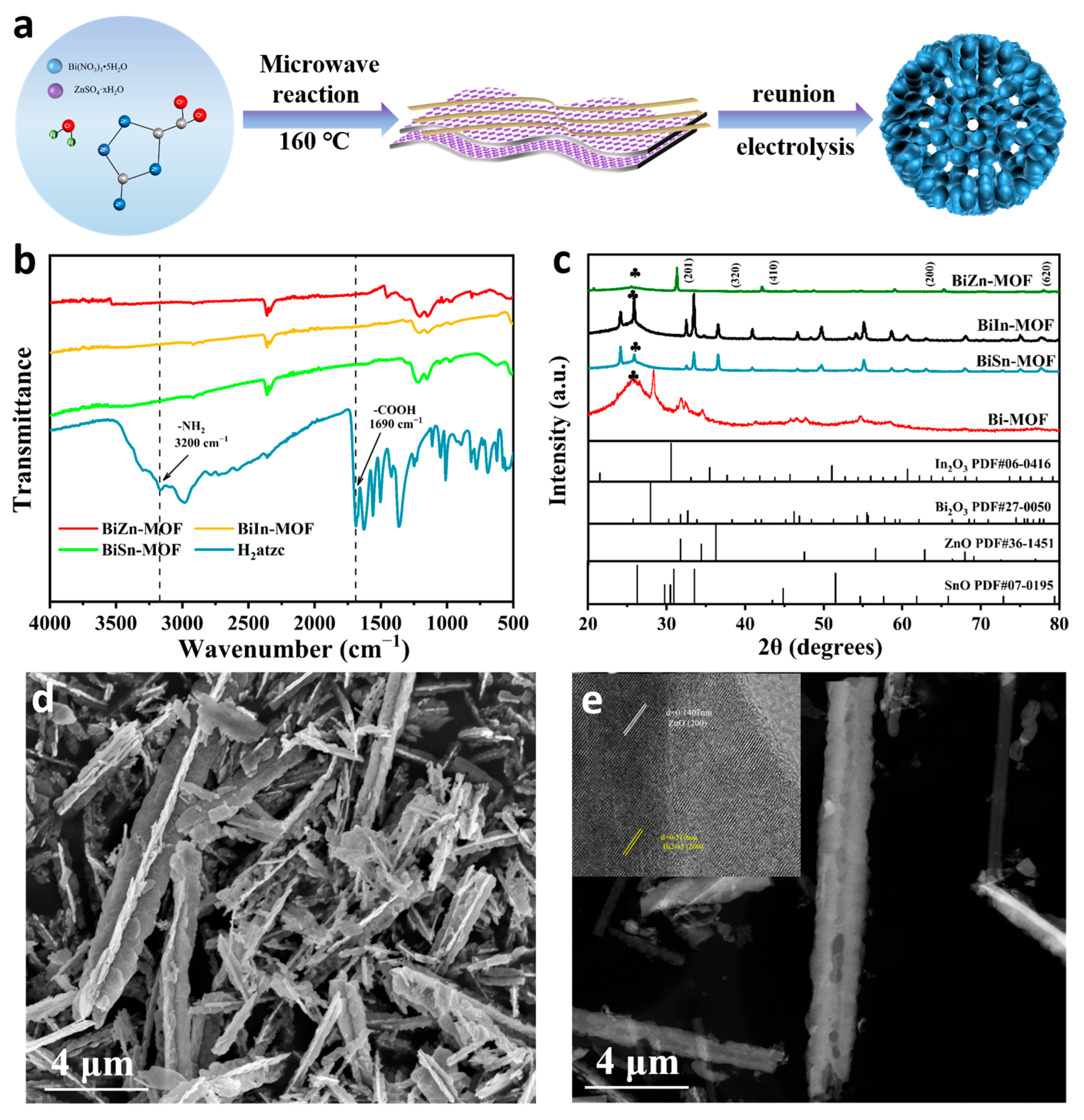
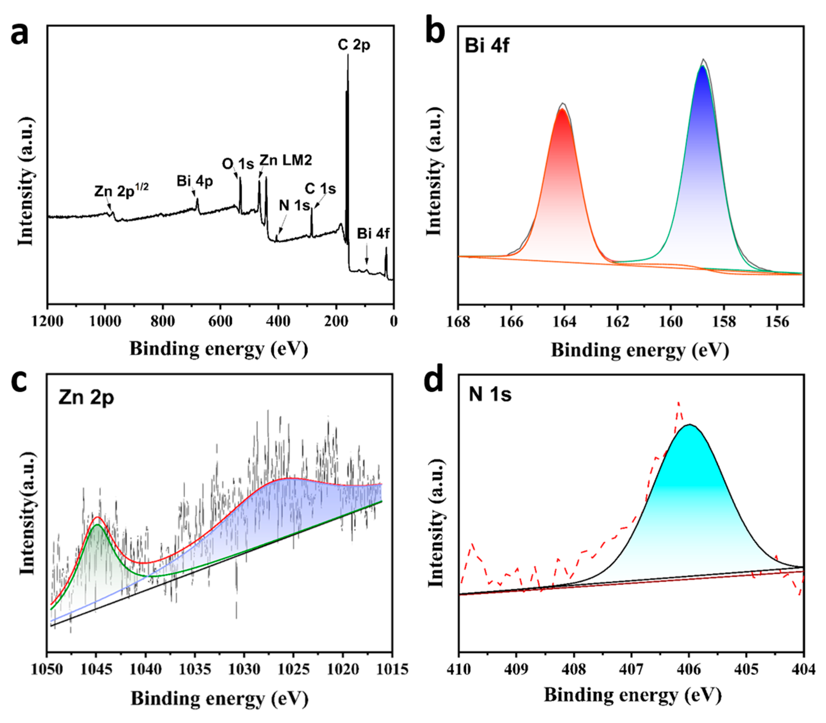
2.1. Morphology and Structure of Bimetallic MOF

Figure 1a shows the synthesis procedure of BiZn-MOF. The synthesis routes of BiIn-MOF and BiSn-MOF are similar to that of BiZn-MOF. By using 3-amino-1H-1,2,4-triazole-5-carboxylic acid hydrate (H2atzc) as an organic ligand, the catalysts BiZn-MOF, BiIn-MOF, and BiSn-MOF were successfully prepared through a rapid microwave approach. To verify the coordination environments of BiZn-MOF, BiIn-MOF, and BiSn-MOF catalysts, Fourier transform infrared spectroscopy (FT-IR) was performed, as shown in Figure 1b. The infrared absorption bands in the range of 3400 cm−1 to 3500 cm−1 for BiZn-MOF, BiIn-MOF, and BiSn-MOF catalysts can be attributed to O-H absorption bands in water molecules. H2atzc exhibits a stretching vibration at 1690 cm−1 due to C=O in the carboxyl group, and a plane stretching vibration mode at 3200 cm−1 due to N-H in the amino group. It is worth noting that the characteristic peaks at 1690 cm−1 and 3200 cm−1 did not appear in the BiZn-MOF, BiIn-MOF, and BiSn-MOF catalysts. Therefore, the carboxyl and amino functional groups of the organic ligand H2atzc successfully coordinated with the metal centers. Powder X-ray diffraction (XRD) patterns were conducted to further investigate the phase structure of BiZn-MOF, BiIn-MOF, BiSn-MOF, and Bi-MOF catalysts. Figure 1c shows that the diffraction peaks of all four catalysts match their respective characteristic peaks. The pattern of BiZn-MOF corresponded to the characteristic peaks of standard cards (PDF#27-0050) and (PDF#36-1451), respectively. The characteristic peaks at 27.95°, 42.05°, 48.44°, and 77.99° correspond to the (201), (320), (410), and (620) crystal faces of Bi2O3, respectively. The characteristic peaks at 31.76°, 34.42°, 47.53°, 56.60°, and 66.38° correspond to the (100), (002), (102), (110), and (200) crystal faces of ZnO, respectively. These results suggested that some oxides were formed on the MOF surface. A combination of XRD and FTIR indicated the successful preparation of BiZn-MOF, BiIn-MOF, and BiSn-MOF catalysts.
Figure S1a–c and Figure 1d showed the scanning electron microscope (SEM) images of the catalysts Bi-MOF, BiIn-MOF, BiSn-MOF and BiZn-MOF, respectively. The catalyst Bi-MOF has a spindle-like structure, but the bimetallic MOF showed a different morphology due to the incorporation of different metal ions Zn2+, Sn4+, and In3+. From SEM images, the catalyst BiZn-MOF presented a nanorod morphology, which were nano-assemblies formed by the accumulation of nanosheets and nanowires. The catalyst BiIn-MOF is an irregular nanosheet. The catalyst BiSn-MOF has a thick flaky nanoflower structure. The Brunner–Emmet–Teller (BET) technique was used to measure the specific surface area of the Bi-BTC catalyst, as shown in Figure S1d. There are a large number of pores on the surface of the nano-rod-like BiZn-MOF catalyst and the pore volume is 0.231 cm3/g. The catalyst has a specific surface area of 8.717 m2/g, which provides more active sites for the reaction interface. The unique structure and large specific surface area of BiZn-MOF provide a theoretical basis for excellent electrocatalytic performance in subsequent electrochemical CO2RR.
Transmission electron microscopy (TEM) was used to further determine the morphology and composition of the catalysts. Figure 1e reveals that the morphology of BiZn-MOF was nanorods. The top right diagram in Figure 1e shows obvious lattice streaks of ZnO and Bi2O3 in a high-resolution transmission electron microscope (HRTEM), with a lattice spacing of 0.141 nm and 0.319 nm corresponding to the (200) crystal face of ZnO and the (201) crystal face of Bi2O3, respectively. The scanning map of element distribution in Figure S2a–d confirmed that the morphology of BiZn-MOF is a nano-composite formed by the accumulation of nanosheets and nanowires. All elements are evenly distributed, which proves the successful preparation and synthesis of BiZn-MOF. Energy dispersive X-ray spectrum (EDX, Figure S2e) verifies the existence of Bi and Zn elements and uniform distribution on the catalyst BiZn-MOF. The atomic content of Bi and Zn was 33% and 0.03%, respectively.
The chemical composition and valence state of the BiZn-MOF catalyst were analyzed by XPS. The obtained XPS spectra were calibrated by aligning the position of peak C(sp2) in the C 1s spectrum with its reference value of 284.4 eV. Figure 2a shows the full XPS spectra of BiZn-MOF, which consists of elements Bi, Zn, C, O, and N. In Figure 2b, the sub-peaks at 165 eV and 159 eV in the Bi 4f spectrogram indicate the presence of metal ion Bi3+. The weak peaks at 1045 and 1028 eV in Figure 2c correspond to the Zn 2p in the catalyst. In Figure 2d, the N 1s spectrum at 406 eV demonstrated the existence of N-H bonding in the MOF catalyst.

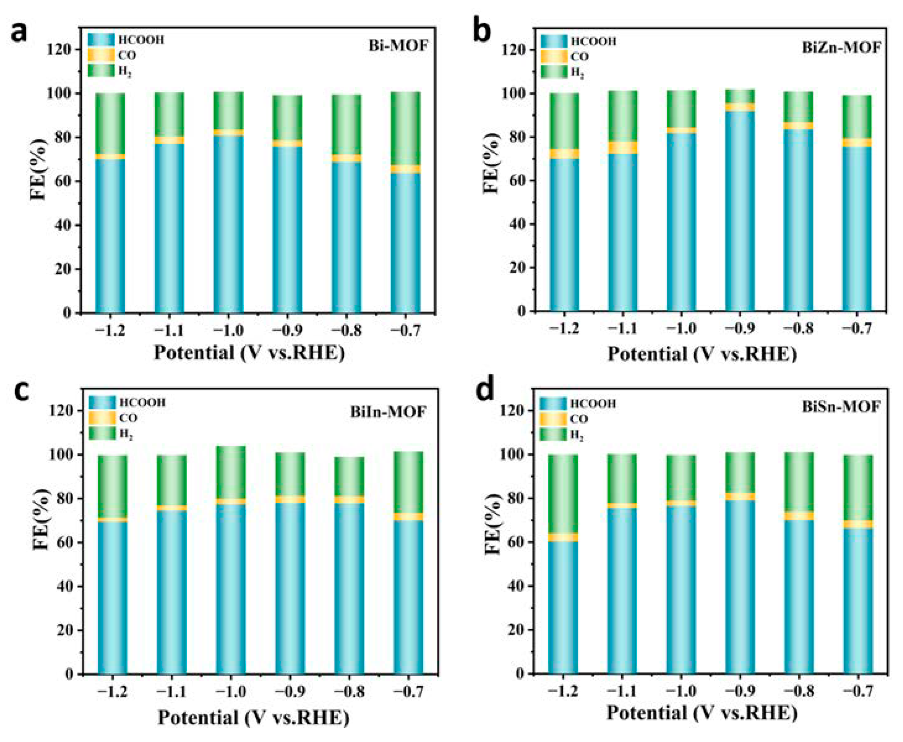
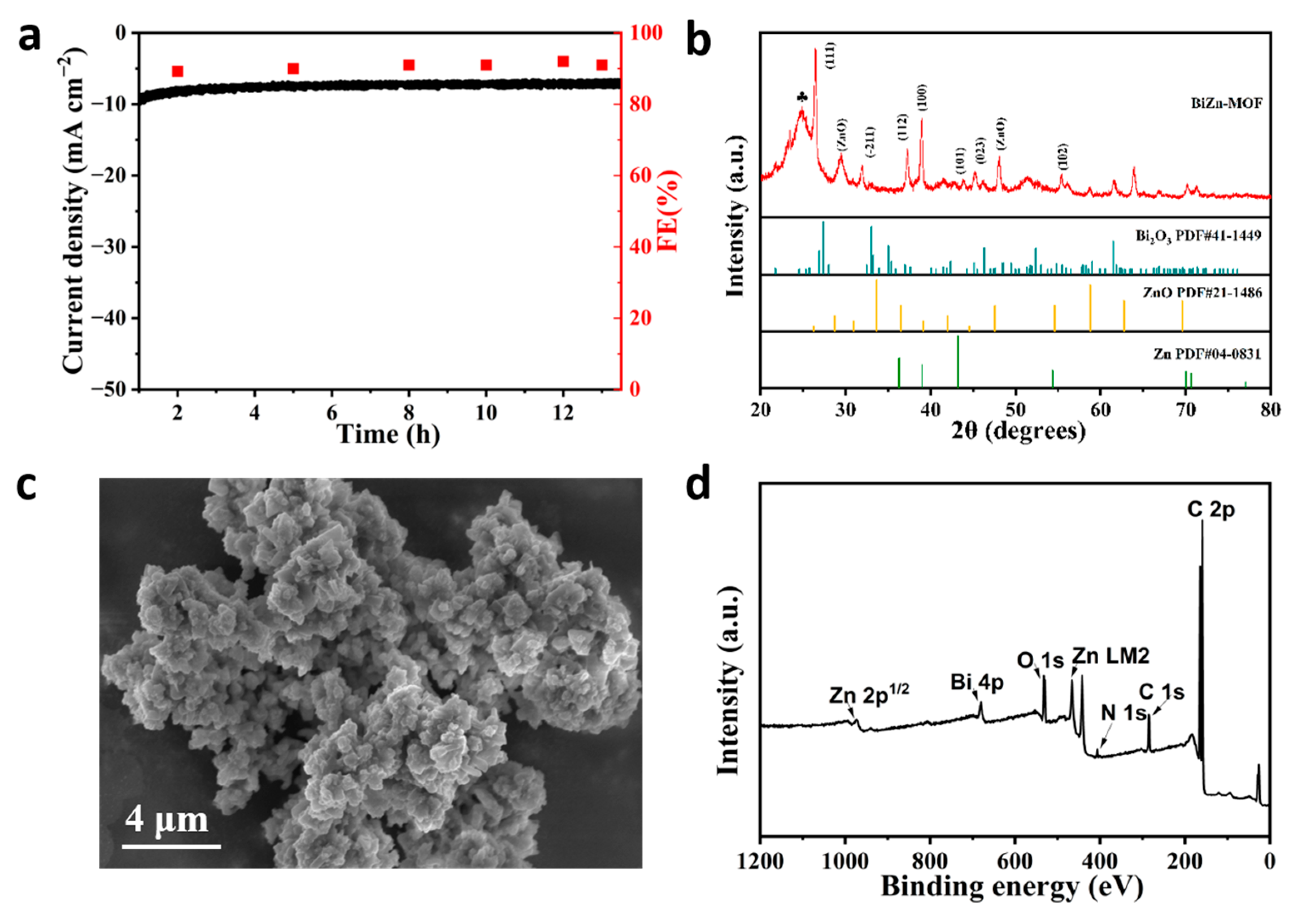
2.2. Electrocatalytic Performance of CO2RR

To evaluate the electrochemical properties of BiZn-MOF, BiIn-MOF, BiSn-MOF, and Bi-MOF catalysts, linear sweep voltammetry (LSV) curves were first tested using an H-type cell in an electrolyte saturated with CO2 or N2. As shown in Figure 3a, the current density of BiZn-MOF to CO2RR in a saturated CO2 electrolyte is obviously higher than that in a saturated N2 electrolyte. This result indicates that the catalyst BiZn-MOF exhibits good electrochemical CO2RR performance and can significantly suppress the generation of by-products (H2 and CO). The electrochemical CO2RR current density of BiZn-MOF is higher than that of BiIn-MOF, BiSn-MOF, and Bi-MOF, indicating better catalytic activity for BiZn-MOF compared to those for BiIn-MOF, BiSn-MOF, and Bi-MOF, as shown in Figure 3b. From Figure 3c, the catalyst BiZn-MOF has higher current density and corrected initial potential than the BiIn-MOF, BiSn-MOF, and Bi-MOF catalysts, indicating its superior electrocatalytic performance for CO2RR. Figure 3d illustrates the Faraday efficiency (FEformate) of formate products by four catalysts. The BiZn-MOF exhibits the best catalytic performance among two-component catalysts. At a potential of −0.9 V (vs. RHE), the FEformate reached 92%, which was superior to Bi-MOF (with an FEformate of 78%). This indicates that successful coordination of the dual metal center enhances formate selectivity, and BiZn-MOF exerts a bimetallic synergistic effect. Compared with the single component Bi-MOF, BiZn-MOF improves the selectivity of electrocatalytic CO2 and promotes the formation of formate. Figure 4a–d present a “volcano” diagram showing the selectivity of electrochemical CO2RR for various products (HCOOH, CO, and H2) prepared by four catalysts at different potentials. The peak values of BiZn-MOF, BiIn-MOF, BiSn-MOF, and Bi-MOF formate are 92%, 78%, 79.5%, and 82%, respectively. BiZn-MOF exhibits the highest selectivity for formate.
To further investigate the effect of the electrochemical active surface area (ECSA), cyclic voltammetry (CV) curves were obtained for four catalysts (Bi-MOF, BiZn-MOF, BiIn-MOF, and BiSn-MOF) at different sweep speeds (20–120 mV s−1), as shown in Figure S3a–d. The linear curve was plotted with sweep speed on the horizontal axis and current density difference on the vertical axis. The slope Cdl of the linear regression line reflects the magnitude of ECSA. Figure S3e shows that the Cdl (180 μF cm−2) of BiZn-MOF in the two-component catalyst is similar to that of Bi-MOF (150 μF cm−2). This result confirmed that the differences in CO2RR performance among the four catalysts mainly depend on optimizing the bimetallic centers, not the ECSA. Electrochemical impedance spectroscopy (EIS) was used to study electrode reaction kinetics at the interface between the electrode and electrolyte. From the EIS in Figure S4a, the semi-circle radius of BiZn-MOF in the two-component catalyst is the smallest (6 Ω), smaller than that of Bi-MOF (27 Ω), BiIn-MOF (9 Ω), and BiSn-MOF (8 Ω). This reflects that with the insertion of Zn2+, the charge transfer rate of BiZn-MOF is accelerated, thus boosting the catalytic activity to CO2RR. To better understand the reaction kinetics of BiZn-MOF, BiSn-MOF, and BiIn-MOF catalysts, Tafel slope analysis was performed. As shown in Figure S4b, the Tafel slopes of BiZn-MOF (106 mV dec−1) and BiIn-MOF (104 mV dec−1) are lower than that of BiSn-MOF (140 mV dec−1). These results indicate that the electron transfer rate of BiZn-MOF and BiIn-MOF catalysts is fast, which is conducive to the adsorption and desorption of *CO on their surfaces.
Figure S5a–c display the constant potential electrolysis of CO2 at various potentials. The stable current density indicates that BiZn-MOF, BiIn-MOF, and BiSn-MOF catalysts exhibit good electrochemical stability in the CO2RR. By further exploring the stability of CO2RR materials, BiZn-MOF decomposes for about 13 h at a potential of −0.9 V (vs. RHE) in Figure 5a. The current density of BiZn-MOF remains stable at 13 mA cm−2, and the Faraday efficiency of producing formate products by electrochemical CO2RR is approximately 92%. These results indicate that BiZn-MOF exhibits good stability towards CO2RR.
XRD was used to further confirm the phase purity and composition of the BiZn-MOF catalyst after electrolysis, as shown in Figure 5b. It was observed that new characteristic diffraction peaks appeared after CO2 electrolysis. By comparing the standard cards (PDF#04-0831) and (PDF#41-1449), diffraction peaks at 36.29°, 38.99°, 43.23°, 54.33°, 70.66°, and 77.02° corresponded to crystal faces (002), (100), (101), (102), (110), and (004) of Zn, respectively. The angles of 26.92° and 32.48°corresponded to Bi2O3’s crystal faces of (111) and (−211). This is because some Zn2+ was reduced to Zn after the electrolysis of the catalyst BiZn-MOF. The SEM image in Figure 5c reveals that agglomeration occurred on the surface of BiZn-MOF after electrolysis, mainly due to structural changes caused by the partial reduction of Zn2+. Figure 5d shows survey XPS spectra, indicating that BiZn-MOF still contains elements Bi, Zn, C, N, and O after electrolysis. The XPS spectrum of Bi 4f in Figure S6a reveals the presence of metal ion Bi3+ at peaks of 165 eV and 159 eV, which was consistent with the results from the XRD pattern. In Figure S6b, the Zn 2p spectrum shows that the binding energy at 1021 eV corresponds to the diffraction peak of Zn (0), and the peak signal changed, mainly due to the low content of Zn in the BiZn-MOF catalyst and partial shedding (wt = 0.02%) after electrolysis. In Figure S6c, N 1s spectra show the same coordination pattern as that of the pre-electrolysis catalyst BiZn-MOF. In Figure S7a, the energy dispersive X-ray spectrometer (EDX) shows that Bi and Zn elements were evenly distributed on the catalyst BiZn-MOF after electrolysis, which verified the presence of Zn elements post-electrolysis. The content of Bi and Zn is 69.66% and 0.02%, respectively, indicating that some Zn may have been lost during the electrolysis process of BiZn-MOF, resulting in a decrease in its content. The element distribution mapping further confirmed that agglomeration occurred on the surface of the BiZn-MOF catalyst after electrolysis, while the elements C (blue), N (purple), O (yellow), Bi (red), and Zn (green) were uniformly distributed.
Electrochemical CO2RR is a promising electrocatalytic technology, but due to the slow kinetics of oxygen evolution (OER) at the anode during electrolysis, a large amount of energy is needed. BiZn-MOF exhibited excellent electrocatalytic activity and selectivity in the process of electrocatalytic CO2 reduction. To confirm the practical application of the BiZn-MOF catalyst, a whole electrolytic cell was assembled by coupling the cathode material BiZn-MOF with the anode material IrO2. Figure 6a shows that a current density of 9 mA cm−2 can be achieved with a cell voltage of 3.5 V and 5 mA cm−2 at 3.0 V. After constant potential current–time curve (I-t) test on CO2RR‖OER (Figure 6b), it is found that BiZn-MOF‖IrO2 can maintain stability for up to 10 h at 3.0 V, indicating application prospects for BiZn-MOF‖IrO2, despite the expensive anode material IrO2, which has good stability and OER catalytic activity.

2.3. Catalytic Mechanism

To better study the reaction pathway and mechanism of electrocatalytic CO2RR for formate formation by a catalyst, in situ Fourier transform infrared spectroscopy (FT-IR) was used to detect catalytic reaction intermediates. The FT-IR spectra can reflect the molecular structure, identify structural composition, and determine the presence of chemical groups [35], thus enabling the detection of reaction intermediates. In Figure 7a, FTIR of BiZn-MOF was tested in a CO2-saturated 0.5 M KHCO3 electrolyte with different potential windows (−1.2V to −1.7 V) for electrolysis. Distinct peaks of *CO2 intermediates are observed within the wavelength range of 1150 cm−1 and 1704 cm−1, which play a crucial role in electrocatalytic CO2 reduction to formate. Additionally, the characteristic absorption peak of CO32− is observed at 1450 cm−1, while the stretching vibration of the C-O bond in CO32− manifests at 1510 cm−1 [36]. The symmetrical tensile vibration of OCO in *OCHO intermediates is observed at 1435 cm−1. The vibration pattern of OCO was also observed during the adsorption of *OCHO intermediates and formate. The FTIR in Figure 7b displays a distinctive peak at 1435 cm−1. With the intensity gradually increasing as the electrolysis time extends, indicating an increase in the vibration mode of OCO. This result further clarifies the electrochemical CO2RR to formate followed the *OCHO reaction pathway.
When preparing formate (or formic acid) via electrochemical CO2RR, two reaction pathways exist [37]:
CO2 + H+ + e → *OCHO (or *COOH) + H+ + e → HCOOH
The final transformation of the reaction intermediate into either HCOOH or CO is affected by the pH of the electrolyte, which is a key factor in determining the product. Generally speaking, alkaline conditions are more conducive to forming *OCHO intermediates [38,39,40]. This study employs a 0.5 M KHCO3 solution (pH = 8.2) with an alkaline condition, so it is more conducive to *OCHO formation, thus obtaining e to generate formate (or formic acid). Simultaneously, *OCHO exhibits enhanced affinity towards the bimetallic active centers Bi and Zn in catalytic material BiZn-MOF, leading to the formation of Bi-O and Zn-O bonds that ensure surface stability [41]. Due to the strong electron-withdrawing ability of *COOH, it favors the formation of Bi-C or Zn-C bonds and C-C coupling [42]. However, in this study, only HCOOH and CO products were detected instead of C2 products, which further supports the proposed *OCHO reaction pathway.

3. Materials and Methods

3.1. Synthesis of Bimetallic MOF Catalysts

Firstly, ZnSO4·xH2O (69.41 mg) and Bi (NO3)3·5H2O (340 mg) were dissolved in deionized water (60 mL), and then mixed with H2atzc (89.7 mg). Subsequently, it was stirred at room temperature for 30 min and transferred to a microwave reactor at 160 °C for 1.5 h. Finally, the catalytic materials BiZn-MOF were centrifuged three times and then put into a drying oven at 60 °C to dry the samples. The other three catalysts (BiIn-MOF, BiSn-MOF, and Bi-MOF) were prepared with a similar procedure to BiZn-MOF by changing the metal sources.

3.2. Electrochemical Measurements

The carbon paper was ultrasonic in acetone and deionized water for 1 h. Then, 5 mg of BiZn-MOF (or BiIn-MOF, BiSn-MOF, and Bi-MOF) was put into 50 μL Nafion solution, 500 μL deionized water, and 450 μL ethanol and ultrasound to prepare the catalyst ink. Finally, a dried carbon paper (1 cm × 1 cm) with a load of 1 mg/cm2 catalyst was prepared by transferring appropriate ink drops onto the carbon paper.
All electrochemical tests were carried out at room temperature, using a type H cell for this work. The cathode chamber and the anode chamber were separated by a proton exchange membrane. A certain volume of 0.5 M KHCO3 electrolyte was measured in the cathode chamber and the anode chamber. In the preparation stage of the experiment, the inlet flow rate was 20 mL/min and CO2 gas was ventilated for 40 min until the electrolyte in the cathode chamber reached saturation. A three-electrode system was adopted, with platinum sheet as the counter electrode and Ag/AgCl (saturated KCl) as the reference electrode and the working electrode in the cathode chamber. After that, the three electrodes were kept at the same height. All electrochemical tests were performed on the electrochemical work station (Shanghai Chenhua, CHI 760D, China) where the pH of the CO2-saturated electrolyte was 6.8. All potentials in this study were measured with respect to Ag/AgCl reference electrodes. The calculation formula is as follows:
E ( v s . R H E ) = E v s . A g / A g C l + 0.222 V + 0.0591 × p H

3.3. Product Analysis

The gas phase product was directly detected by gas chromatography (GC7900, Tianmei, China) after coming out of the gas outlet of the H-type electrolytic cell. The carbon-containing gas products in the cathode chamber were analyzed by a methane reformer and a flame ionization detector (FID). A thermal detector (TCD) was used to detect CO2RR byproduct H2. Gas products (CO, H2) are detected when the current tends to be stable. The Faraday efficiency of gas products is calculated as follows:
F E ( H 2 / C O ) = v × t × C × N × F 60 × 24 × 1000 × Q × 100 % = v × C × 2 × 96485 60 × 24000 × Q × 100 %
where ν represents the supplied CO2 gas flow rate (20 mL/min), C denotes the concentration of H2 (or CO) in the GC sample ring, N is the number of electrons transferred by H2 or CO molecules (N = 2), F stands for Faraday efficiency (96,485 C/mol), and Q represents the amount of electrolytic charge.
The liquid products after electrolysis were detected by ion chromatography (AS-DV, Thermo Scientific, New York City, NY, USA). Several quantities of formate products were collected from the cathode chamber in the H-type electrolytic cell and injected into the ion chromatography. The concentration (ppm) of formate in liquid phase products was determined by the integral area of the HCOO standard curve. Faraday’s formula is as follows:
F E f o r m a t e ( % ) = n f o r m a t e × N × F Q × 100 % = C f o r m a t e × V × 2 × 96,485 I × t × 100 %
where nformate is the molar amount of formate in the cathode chamber, N represents the number of electrons required to generate HCOO, F denotes the Faraday constant (96,485 C/mol), and Q indicates the amount of electron transfer charge (C). For each potential, the liquid phase product in the cathode chamber was collected 3–4 times to obtain an average value. The liquid phase product was then detected using ion chromatography. The concentration of the liquid phase product was calculated based on the peak area of a standard curve, allowing for determination of the Faraday efficiency of formate production.

4. Conclusions

In summary, bimetallic catalysts BiZn-MOF, BiSn-MOF, and BiIn-MOF were successfully synthesized using a rapid microwave method. The optimized catalyst BiZn-MOF exhibits good catalytic activity for electrochemical CO2 reduction to formate. At a potential of −0.9 V (vs. RHE), the formate Faradaic efficiency reaches 92%. The good catalytic performance of BiZn-MOF may be attributed to the Bi-Zn bimetallic coordination centers in the MOF, which can reduce the binding energies of the reaction intermediates by tuning the electronic structure and atomic arrangement. This study presents a rational and low-cost design concept for bimetallic catalysts in CO2RR research using a facile microwave method.

Supplementary Materials

The following supporting information can be downloaded at https://www.mdpi.com/article/10.3390/ijms241813838/s1.

Author Contributions

Conceptualization, J.P.; methodology, R.Y. and Q.H.; formal analysis, Q.H. and X.S.; investigation, R.Y. and Q.H.; resources, J.P.; data curation, R.Y. and Q.H.; writing—original draft preparation, R.Y., Q.H. and J.P.; writing—review and editing, J.P.; visualization, X.S. and B.G.; project administration, J.P.; funding acquisition, B.G. and J.P. All authors have read and agreed to the published version of the manuscript.

Funding

This work was funded with support from the National Natural Science Foundation of China (No. 22262027). We also acknowledged College Students’ Innovative and Entrepreneurship Training Program of Ningxia University (No. G202210749020).

Institutional Review Board Statement

Not applicable.

Informed Consent Statement

Not applicable.

Data Availability Statement

All data in this study can be found in public databases and Supplementary Information, as described in the Material and Methods section (Section 3).

Conflicts of Interest

The authors declared no competing financial interest.

References

  1. Fernández-Torres, M.J.; Dednam, W.; Caballero, J.A. Economic and environmental assessment of directly converting CO2 into a gasoline fuel. Energy Convers. Manag. 2022, 252, 115115. [Google Scholar] [CrossRef]
  2. Vidal-López, A.; Posada-Pérez, S.; Solà, M.; Poater, A. Au Single Metal Atom for Carbon Dioxide Reduction Reaction. Chemistry 2023, 5, 1395–1406. [Google Scholar] [CrossRef]
  3. Ma, W.; He, X.; Wang, W.; Xie, S.; Zhang, Q.; Wang, Y. Electrocatalytic reduction of CO2 and CO to multi-carbon compounds over Cu-based catalysts. Chem. Soc. Rev. 2021, 50, 12897–12914. [Google Scholar] [CrossRef]
  4. Posada-Pérez, S.; Ramírez, P.J.; Evans, J.; Viñes, F.; Liu, P.; Illas, F.; Rodriguez, J.A. Highly active Au/δ-MoC and Cu/δ-MoC catalysts for the conversion of CO2: The metal/C ratio as a key factor defining activity, selectivity, and stability. J. Am. Chem. Soc. 2016, 138, 8269–8278. [Google Scholar] [CrossRef]
  5. Zhang, S.-Y.; Yang, Y.-Y.; Zheng, Y.-Q.; Zhu, H.-L. Ag-doped Co3O4 catalyst derived from heterometallic MOF for syngas production by electrocatalytic reduction of CO2 in water. J. Solid State Chem. 2018, 263, 44–51. [Google Scholar] [CrossRef]
  6. Zarandi, R.F.; Rezaei, B.; Ghaziaskar, H.S.; Ensafi, A.A. Electrochemical conversion of CO2 to methanol using a glassy carbon electrode, modified by Pt@ histamine-reduced graphene oxide. Int. J. Hydrogen Energy 2019, 44, 30820–30831. [Google Scholar] [CrossRef]
  7. Wang, J.; Li, X.; Zheng, J.; Cao, J.; Hao, X.; Wang, Z.; Abudula, A.; Guan, G. Non-precious molybdenum-based catalyst derived from biomass: CO-free hydrogen production from formic acid at low temperature. Energy Convers. Manag. 2018, 164, 122–131. [Google Scholar] [CrossRef]
  8. Li, Y.; Yan, Y.; He, Y.; Du, S. Catalyst electrodes with PtCu nanowire arrays in situ grown on gas diffusion layers for direct formic acid fuel cells. ACS Appl. Mater. Interfaces 2022, 14, 11457–11464. [Google Scholar] [CrossRef]
  9. Kang, D.; Byun, J.; Han, J. Evaluating the environmental impacts of formic acid production from CO2: Catalytic hydrogenation vs. electrocatalytic reduction. Green Chem. 2021, 23, 9470–9478. [Google Scholar] [CrossRef]
  10. Piqué, O.; Vines, F.; Illas, F.; Calle-Vallejo, F. Elucidating the structure of ethanol-producing active sites at oxide-derived Cu electrocatalysts. ACS Catal. 2020, 10, 10488–10494. [Google Scholar] [CrossRef]
  11. Posada-Pérez, S.; Vidal-López, A.; Solà, M.; Poater, A. 2D carbon nitride as a support with single Cu, Ag, and Au atoms for carbon dioxide reduction reaction. Phys. Chem. Chem. Phys. 2023, 25, 8574–8582. [Google Scholar] [CrossRef] [PubMed]
  12. Zhu, C.; Wang, Q.; Wu, C. Rapid and scalable synthesis of bismuth dendrites on copper mesh as a high-performance cathode for electroreduction of CO2 to formate. J. CO2 Util. 2020, 36, 96–104. [Google Scholar] [CrossRef]
  13. Li, M.; Wang, H.; Luo, W.; Sherrell, P.C.; Chen, J.; Yang, J. Heterogeneous single-atom catalysts for electrochemical CO2 reduction reaction. Adv. Mater. 2020, 32, 2001848. [Google Scholar] [CrossRef] [PubMed]
  14. Li, J.; Zhu, M.; Han, Y.F. Recent advances in electrochemical CO2 reduction on indium-based catalysts. ChemCatChem 2021, 13, 514–531. [Google Scholar] [CrossRef]
  15. Yan, L.; Wu, Z.; Li, C.; Wang, J. Sb-doped SnS2 nanosheets enhance electrochemical reduction of carbon dioxide to formate. J. Ind. Eng. Chem. 2023, 123, 33–40. [Google Scholar] [CrossRef]
  16. Ai, L.; Ng, S.-F.; Ong, W.-J. Carbon dioxide electroreduction into formic acid and ethylene: A review. Environ. Chem. Lett. 2022, 20, 3555–3612. [Google Scholar] [CrossRef]
  17. Pavesi, D.; Ali, F.S.; Anastasiadou, D.; Kallio, T.; Figueiredo, M.; Gruter, G.-J.M.; Koper, M.T.; Schouten, K.J.P. CO2 electroreduction on bimetallic Pd–In nanoparticles. Catal. Sci. Technol. 2020, 10, 4264–4270. [Google Scholar] [CrossRef]
  18. Yang, C.; Hu, Y.; Li, S.; Huang, Q.; Peng, J. Self-Supporting Bi–Sb Bimetallic Nanoleaf for Electrochemical Synthesis of Formate by Highly Selective CO2 Reduction. ACS Appl. Mater. Interfaces 2023, 15, 6942–6950. [Google Scholar] [CrossRef]
  19. Wang, Y.; Cao, L.; Libretto, N.J.; Li, X.; Li, C.; Wan, Y.; He, C.; Lee, J.; Gregg, J.; Zong, H. Ensemble effect in bimetallic electrocatalysts for CO2 reduction. J. Am. Chem. Soc. 2019, 141, 16635–16642. [Google Scholar] [CrossRef]
  20. Han, N.; Ding, P.; He, L.; Li, Y.; Li, Y. Promises of main group metal–based nanostructured materials for electrochemical CO2 reduction to formate. Adv. Energy Mater. 2020, 10, 1902338. [Google Scholar] [CrossRef]
  21. Peng, L.; Wang, Y.; Wang, Y.; Xu, N.; Lou, W.; Liu, P.; Cai, D.; Huang, H.; Qiao, J. Separated growth of Bi-Cu bimetallic electrocatalysts on defective copper foam for highly converting CO2 to formate with alkaline anion-exchange membrane beyond KHCO3 electrolyte. Appl. Catal. B Environ. 2021, 288, 120003. [Google Scholar] [CrossRef]
  22. Wang, M.; Liu, S.; Chen, B.; Tian, F.; Peng, C. Synergistic geometric and electronic effects in Bi–Cu bimetallic catalysts for CO2 electroreduction to formate over a wide potential window. ACS Sustain. Chem. Eng. 2022, 10, 5693–5701. [Google Scholar] [CrossRef]
  23. Allioux, F.-M.; Merhebi, S.; Ghasemian, M.B.; Tang, J.; Merenda, A.; Abbasi, R.; Mayyas, M.; Daeneke, T.; O’Mullane, A.P.; Daiyan, R. Bi–Sn catalytic foam governed by nanometallurgy of liquid metals. Nano Lett. 2020, 20, 4403–4409. [Google Scholar] [CrossRef]
  24. Yao, K.; Wang, H.; Yang, X.; Huang, Y.; Kou, C.; Jing, T.; Chen, S.; Wang, Z.; Liu, Y.; Liang, H. Metal-organic framework derived dual-metal sites for electroreduction of carbon dioxide to HCOOH. Appl. Catal. B Environ. 2022, 311, 121377. [Google Scholar] [CrossRef]
  25. He, C.; Zhang, Y.; Zhang, Y.; Zhao, L.; Yuan, L.P.; Zhang, J.; Ma, J.; Hu, J.S. Molecular evidence for metallic cobalt boosting CO2 electroreduction on pyridinic nitrogen. Angew. Chem. Int. Ed. 2020, 59, 4914–4919. [Google Scholar] [CrossRef]
  26. Wang, K.; Li, Y.; Xie, L.-H.; Li, X.; Li, J.-R. Construction and application of base-stable MOFs: A critical review. Chem. Soc. Rev. 2022, 51, 6417–6441. [Google Scholar] [CrossRef]
  27. Liu, C.; Wang, J.; Wan, J.; Yu, C. MOF-on-MOF hybrids: Synthesis and applications. Coord. Chem. Rev. 2021, 432, 213743. [Google Scholar] [CrossRef]
  28. Ye, Z.; Jiang, Y.; Li, L.; Wu, F.; Chen, R. Rational design of MOF-based materials for next-generation rechargeable batteries. Nano-Micro Lett. 2021, 13, 1–37. [Google Scholar] [CrossRef] [PubMed]
  29. Zhang, X.; Luo, J.; Wan, K.; Plessers, D.; Sels, B.; Song, J.; Chen, L.; Zhang, T.; Tang, P.; Morante, J.R. From rational design of a new bimetallic MOF family with tunable linkers to OER catalysts. J. Mater. Chem. A 2019, 7, 1616–1628. [Google Scholar] [CrossRef]
  30. Du, C.; Wang, X.; Chen, W.; Feng, S.; Wen, J.; Wu, Y. CO2 transformation to multicarbon products by photocatalysis and electrocatalysis. Mater. Today Adv. 2020, 6, 100071. [Google Scholar] [CrossRef]
  31. Guan, X.; Gao, W.; Jiang, Q. Design of bimetallic atomic catalysts for CO 2 reduction based on an effective descriptor. J. Mater. Chem. A 2021, 9, 4770–4780. [Google Scholar] [CrossRef]
  32. Zhong, H.; Ghorbani-Asl, M.; Ly, K.H.; Zhang, J.; Ge, J.; Wang, M.; Liao, Z.; Makarov, D.; Zschech, E.; Brunner, E. Synergistic electroreduction of carbon dioxide to carbon monoxide on bimetallic layered conjugated metal-organic frameworks. Nat. Commun. 2020, 11, 1409. [Google Scholar] [CrossRef]
  33. Ye, K.; Cao, A.; Shao, J.; Wang, G.; Si, R.; Ta, N.; Xiao, J.; Wang, G. Synergy effects on Sn-Cu alloy catalyst for efficient CO2 electroreduction to formate with high mass activity. Sci. Bull. 2020, 65, 711–719. [Google Scholar] [CrossRef] [PubMed]
  34. Shen, F.-X.; Shi, J.; Chen, T.-Y.; Shi, F.; Li, Q.-Y.; Zhen, J.-Z.; Li, Y.-F.; Dai, Y.-N.; Yang, B.; Qu, T. Electrochemical reduction of CO2 to CO over Zn in propylene carbonate/tetrabutylammonium perchlorate. J. Power Sources 2018, 378, 555–561. [Google Scholar] [CrossRef]
  35. Zu, X.; Zhao, Y.; Li, X.; Chen, R.; Shao, W.; Wang, Z.; Hu, J.; Zhu, J.; Pan, Y.; Sun, Y. Ultrastable and efficient visible-light-driven CO2 reduction triggered by regenerative oxygen-vacancies in Bi2O2CO3 nanosheets. Angew. Chem. Int. Ed. 2021, 60, 13840–13846. [Google Scholar] [CrossRef]
  36. Xing, Y.; Kong, X.; Guo, X.; Liu, Y.; Li, Q.; Zhang, Y.; Sheng, Y.; Yang, X.; Geng, Z.; Zeng, J. Bi@ Sn core–shell structure with compressive strain boosts the electroreduction of CO2 into formic acid. Adv. Sci. 2020, 7, 1902989. [Google Scholar] [CrossRef]
  37. Yang, W.; Dastafkan, K.; Jia, C.; Zhao, C. Design of electrocatalysts and electrochemical cells for carbon dioxide reduction reactions. Adv. Mater. Technol. 2018, 3, 1700377. [Google Scholar] [CrossRef]
  38. Kwon, I.S.; Debela, T.T.; Kwak, I.H.; Seo, H.W.; Park, K.; Kim, D.; Yoo, S.J.; Kim, J.-G.; Park, J.; Kang, H.S. Selective electrochemical reduction of carbon dioxide to formic acid using indium–zinc bimetallic nanocrystals. J. Mater. Chem. A. 2019, 7, 22879–22883. [Google Scholar] [CrossRef]
  39. Jiang, H.; Zhao, Y.; Wang, L.; Kong, Y.; Li, F.; Li, P. Electrochemical CO2 reduction to formate on Tin cathode: Influence of anode materials. J. CO2 Util. 2018, 26, 408–414. [Google Scholar] [CrossRef]
  40. Hai, G.; Xue, X.; Feng, S.; Ma, Y.; Huang, X. High-Throughput Computational Screening of Metal–Organic Frameworks as High-Performance Electrocatalysts for CO2RR. ACS Catal. 2022, 12, 15271–15281. [Google Scholar] [CrossRef]
  41. Fernández-Caso, K.; Díaz-Sainz, G.; Alvarez-Guerra, M.; Irabien, A. Electroreduction of CO2: Advances in the continuous production of formic acid and formate. ACS Energy Lett. 2023, 8, 1992–2024. [Google Scholar] [CrossRef]
  42. Guo, Z.; Zhang, Q.; Wang, H.; Tan, X.; Shi, F.; Xiong, C.; Man, N.; Hu, H.; Liu, G.; Jiang, J. Bi–Zn codoping in GeTe synergistically enhances band convergence and phonon scattering for high thermoelectric performance. J. Mater. Chem. A 2020, 8, 21642–21648. [Google Scholar] [CrossRef]
Figure 1. (a) Scheme illustration of the synthetic route for BiZn-MOF. (b) FT-IR spectra. (c) XRD patterns. The symbol ♣ indicates the characteristic peak of carbon paper. (d) SEM images of BiZn-MOF. (e) TEM and HRTEM images of BiZn-MOF.
Ijms 24 13838 g001
Figure 2. (a) XPS survey spectra of BiZn-MOF, (b) Bi 4f spectrum of BiZn-MOF, (c) Zn 2p spectrum of BiZn-MOF and (d) N 1s spectrum of BiZn-MOF.
Ijms 24 13838 g002
Figure 3. (a) Polarization curves of BiZn-MOF in saturated CO2 and N2 atmospheres, respectively; (b) Polarization curves of BiZn-MOF, BiIn-MOF, BiSn-MOF, and Bi-MOF catalysts in saturated CO2 electrolyte; (c) Local current densities; (d) Faraday efficiency of formate.
Ijms 24 13838 g003
Figure 4. FEs of HCOO, H2, and CO: (a) Bi-MOF, (b) BiZn-MOF, (c) BiIn-MOF, and (d) BiSn-MOF.
Ijms 24 13838 g004
Figure 5. (a) Long-term stability of BiZn-MOF at −0.9 V (vs. RHE) potential and FE of HCOO. Characterizations of BiZn-MOF catalyst after electrolysis for 10 h: (b) XRD pattern. The symbol ♣ indicates the characteristic peak of carbon paper. (c) SEM image of BiZn-MOF. (d) XPS spectra of BiZn-MOF.
Ijms 24 13838 g005
Figure 6. Performance of the CO2RR∥OER full cell for overall CO2 splitting: (a) LSV curves for the CO2RR∥OER full cell based on the BiZn-MOF∥IrO2 pair and (b) I-t curves at 3.0 V in CO2RR∥OER full cell.
Ijms 24 13838 g006
Figure 7. In situ FTIR of BiZn-MOF: (a) electrolysis at a potential of −1.2 V to −1.7 V for 1 h, and (b) at a potential of −0.9 V (vs. RHE) for different electrolysis times.
Ijms 24 13838 g007
Disclaimer/Publisher’s Note: The statements, opinions and data contained in all publications are solely those of the individual author(s) and contributor(s) and not of MDPI and/or the editor(s). MDPI and/or the editor(s) disclaim responsibility for any injury to people or property resulting from any ideas, methods, instructions or products referred to in the content.

