Article

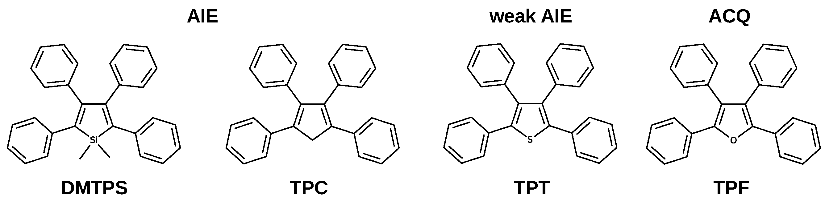
Emission Quenching in Tetraphenylfuran Crystal: Why This Propeller-Shaped Molecule Does Not Emit in the Condensed Phase

by
Ljiljana Stojanović
1,2 and
Rachel Crespo-Otero
1,*
1
School of Physical and Chemical Sciences, Queen Mary University of London, Mile End Road, London E1 4NS, UK
2
Department of Physics and Astronomy, University College London, Gower Street, London WC1E 6BT, UK
*
Author to whom correspondence should be addressed.
Molecules 2022, 27(2), 522; https://doi.org/10.3390/molecules27020522
Submission received: 11 December 2021 / Revised: 6 January 2022 / Accepted: 10 January 2022 / Published: 14 January 2022
(This article belongs to the Special Issue Photophysics and Photochemistry in Complex Molecular Systems)

Abstract

:
Due to their substantial fluorescence quantum yields in the crystalline phase, propeller-shaped molecules have recently gained significant attention as potential emissive materials for optoelectronic applications. For the family of cyclopentadiene derivatives, light-emission is highly dependent on the nature of heteroatomic substitutions. In this paper, we investigate excited state relaxation pathways in the tetraphenyl-furan molecule (TPF), which in contrast with other molecules in the family, shows emission quenching in the solid-state. For the singlet manifold, our calculations show nonradiative pathways associated with C-O elongation are blocked in both vacuum and the solid state. A fraction of the population can be transferred to the triplet manifold and, subsequently, to the ground state in both phases. This process is expected to be relatively slow due to the small spin-orbit couplings between the relevant singlet-triplet states. Emission quenching in crystalline TPF seems to be in line with more efficient exciton hopping rates. Our simulations help clarify the role of conical intersections, population of the triplet states and crystalline structure in the emissive response of propeller-shaped molecules.

1. Introduction

The optimisation of highly emissive organic molecules has become a milestone in the technology of optoelectronic materials. Due to the presence of defects and the stabilisation of specific intermolecular interactions, such as π - π stacking and hydrogen bonds, emission quenching is very common in the condensed phase. In the last decade, several organic crystals showing a significant enhancement of luminescence have been reported. The term aggregation-induced emission (AIE) has been commonly used to describe this phenomenon. The term solid-state luminescence enhancement (SSLE), proposed by Gierschner et al. better highlights the synergistic effect of inter and intramolecular interactions on emission in the solid-state [1].
Two complementary models are widely used to explain AIE and SSLE: restricted access to the conical intersection (RACI) and restriction of intramolecular motions (RIM). According to the RACI model, the conical intersections, which act as funnels for internal conversion (IC) to the ground state, are destabilised in the crystal environment due to the steric hindrance, decreasing the internal conversion rate, and consequently, increasing the fluorescence yield [2,3,4,5,6]. This model is appropriate when a molecule possesses enough energy to explore regions of excited-state surfaces with strong nonadiabatic couplings between the ground and excited states. However, when the energy barrier prevents relaxation through IC, a part of the population can be transferred through vibrational transitions to the ground state, as a result of overlaps between ground and excited state vibrational wave functions. Shuai et al. have derived a formalism based on Fermi’s golden rule, which proves that low-frequency vibrations enhance the IC rate [7]. In crystal environments, where low-frequency motions are partially hindered, the internal conversion rates decrease. This is the basis for the RIM model.
Propeller-shaped molecules are typical systems with an enhanced emission response in the condensed phase [8]. These chromophores are composed of a static core, typically a five-membered aromatic ring, surrounded by phenyl rings as rotors. Several propeller-shaped systems (Figure 1) exhibit significant fluorescence yields in the crystalline phase [8,9,10].
It is expected that propeller-shaped systems derived from furan and thiophene also show AIE properties, however, tetraphenylthiophene (TPT) is a weak AIE-gen, whereas tetraphenylfuran (TPF) exhibits aggregation caused quenching. We have recently studied the relaxation mechanism in crystalline TPT, concluding that active intersystem crossing pathways decrease emission efficiency, even though IC is hampered [10]. Our calculations show that the nature of the central atom can modify the nature of conical intersections involved in the main nonradiative pathways; when the central atom is modified from C, to S and O, the main nonradiative pathways change from puckering to bond breaking. TPF is the only member of the family with significant emission efficiency in solution (0.40). Upon crystallisation to nanoaggregates, the fluorescence is completely lost. According to experimental results, quenching is due to both an increase in nonradiative decay and to a smaller extent to a decrease of radiative decay upon aggregation [11].
Several modifications of TPF have been attempted to improve its radiative response. Contrary to TPT, TPF is not piezoemissive, even though the steric volume significantly decreases within a certain range of applied external pressure [12]. The introduction of bulky substituents in positions 3 and 4 of furan does not improve emissive properties either. However, oxidative ring-opening of furan produces 1,4-enedione [13], whose crystal has a significant fluorescence yield. Another successful approach is the design of 1,2,3,4-tetraphenyloxazolium (TPO-P) and 2,3,5-triphenyloxazolium (TriPO-PN) crystals derived from TPF, which have significant anion- π + interactions that suppress π - π stacking and minimise the intermolecular nonradiative pathways [14].
In this paper, we investigate the main excited-state radiative and nonradiative decay mechanisms of TPF in the vacuum, solution and crystal. We consider the effect of intermolecular interactions, vibrations and exciton formation, and compute reorganisation energies in three phases. By analysing the potential energy surfaces of the ground and excited singlet and triplet states, we identify the minimum energy intramolecular nonradiative pathways in vacuum and crystal. Our calculations show that the minimum energy nonradiative pathway is associated with the C-O bond elongation, however, a high barrier corresponding to the π π * / π σ * intersection, prevents the π σ * state population and access to the conical intersection in both phases. In contrast with related systems, the intermolecular processes seem to play an important role in excited state relaxation in the TPF crystal.

2. Computational Details

To explain the light-activated processes in TPF, we considered its excited states in the gas phase, tetrahydrofuran (THF) solvent, and the crystal phase. The ground state (FC) and S 1 minima were optimised with (TD-)DFT and ω B97X-D/6-31G(d) [15,16,17,18,19,20]. Several electronic structure methods were then assessed for the prediction of the absorption and emission energies. For the simulation of the dielectric environment of tetrahydrofuran (THF) ( ϵ = 7.6), the polarisable continuum model (PCM) was used with the (TD)-B3LYP/6-31G(d) and (TD-) ω B97X-D/6-31G(d) methods, with the linear-response equilibrium variant for the excited states. Optimisations and single-point computations with DFT and TD-DFT were performed with Gaussian 16 [21].
We also considered wave-function methods; resolution-of-the-identity coupled-cluster with approximate second-order excitations (RI-CC2/aug-cc-pVDZ) [22,23,24,25], and complete active space perturbation theory (CASPT2) method [26,27,28]. The CASPT2 calculations were performed in the space of the configuration state functions obtained with SA-3-CASSCF(10,10)/6-31G(d) [29]. The active space was composed of 8 π orbitals with significant occupations and a bonding/antibonding pair of sigma C-O orbitals (Figure S1 in the Supporting Information). The CASPT2 computations were performed with 0.1 au imaginary shift and without an IPEA shift. The S 1 –S 0 minimum energy conical intersections (MECIs) were optimised with the SA-2-CASSCF(10,10)/6-31G(d) level of theory, using the branching plane update method [30] implemented in the Molcas code [31]. The RI-CC2 computations were performed with the Turbomole v7.0 code [32].
The experimental crystal structure of TPF was retrieved from the Cambridge Crystallographic Database (the CCDC code is 1494293) and refined with DFT-periodic boundary conditions as implemented in Quantum Espresso [33]. The PBE-D2 functional was used with a plane-wave cutoff of 30 Ry and a Monkhorst-Pack k-point grid of (1 × 2 × 1), chosen according to the dimensions of the unit cell.
Clusters of 44 molecules were extracted from the optimised supercells for the subsequent QM:MM calculations with electrostatic embedding. The central molecule in the cluster was treated using the QM framework, whereas the surrounding molecules were modelled with MM. The QM region was relaxed whilst the MM region was kept fixed at its optimised lattice positions. FC and S 1 geometries were optimised applying the ONIOM(QM:MM) method [34,35] using the Gaussian 16 software [21]. The QM region was treated using the ω B97X-D/6-31G(d) level of theory under the (TD-)DFT framework. The MM region was simulated with the Amber force field [36] using ESP charges derived from a vacuum HF/3-21G* calculation of the monomer. We also analysed the slip-stacked dimer with the shortest centroid using the ONIOM embedded cluster method (OEC) implemented in fromage [37,38]. The QM (selected dimer) and QM’ (environment) regions were simulated with TD-B3LYP/6-31G(d) and the second order (SCC-)DFTB [39] method, employing the mio-1-1 set of Slater-Koster parameters parametrised for the tight-binding SCC-DFTB Hamiltonian [40]. For the point charges we used the RESP charges obtained at ω B97X-D/6-31G(d) and PBE/6-31G(d) levels of theory, respectively. The DFTB calculations were performed with the DFTB+ program [39].
The S 1 –S 0 MECI and T 1 –S 0 crossing in the solid state were optimised using QM/MM with the interface between the Molcas and Tinker (version 6.3.3) codes. The QM region was described at the SA-2-CASSCF(10,10)/6-31G(d) level of theory, whereas the surrounding molecules were treated using the Amber force field. The pathways connecting FC, S 1 and the crossing geometries in vacuum and crystal were created by restricted SA-2-CASSCF(10,10)/6-31G(d) optimisations of the S 1 state by increasing the C-O bond length. Single point calculations with MS-3-CASPT2/SA-3-CASSCF(10,10)/6-31G(d) were performed on the optimised geometries. We obtained the diabatic representations by analysing the composition of adiabatic states in terms of excitations between CASSCF orbitals and connecting the states of the same type.
The spin-orbit coupling (SOCs) between the first three singlet and triplet states (S 0 –S 2 and T 1 –T 3 ) were computed at relevant geometries with the Molcas code, employing SA-3-(10,10)CASSCF/6-31G(d) ground and excited-state wave functions [31]. The SOCs were calculated using the components of matrix elements between singlets and triplets with quantum numbers m l { 1 , 0 , 1 } as S i | H S O | T j | = m l = 1 , 0 , 1 S i | H S O | T m l , j | 2 .
The fluorescence rates ( k r ) were evaluated using the Einstein equation for spontaneous decay from a state with emission energy ( Δ E ) and oscillator strength (f)
k r E i n = 2 Δ E 2 f c 3
where all variables and constants are represented in atomic units.
The intersystem crossing (ISC) rates ( k I S C ) between S 1 and T 1 /T 2 states were evaluated based on the Marcus-Levich-Jortner model as [41,42,43,44]
k I S C M L J = 2 π S i | H S O | T j 2 1 4 π λ k B T n e x p ( s k ) s k n n ! e x p ( Δ E S T + n ω k + λ ) 2 4 λ k B T
Δ E S T is the energy gap between T m and S n states at their minima, λ is the total reorganisation energy of low-frequency normal modes ( ω j 600 cm 1 ), n is the vibrational quantum number. The higher frequency modes ( ω j > 600 cm 1 ) are represented by a single effective mode with a frequency ω k obtained as
ω k = j ω j s j j s j
where s j and λ j are the Huang-Rhys factors and reorganisation energies of these high frequency modes. The Huang-Rhys factor for the effective mode ( s k ) is calculated as s k = j λ j / ω k . These values were calculated based on the normal modes of the monomers for the S 1 and T 2 minima at the TD-B3LYP/6-31G(d) level of theory in the gas phase, solution, and solid state using the Dushin code [45].
Exciton couplings (J) were computed applying the Troisi’s diabatisation scheme based on the transition dipole moments of isolated molecules and dimers as implemented in fromage [38,46]. This method takes into account short-range (exchange, orbital overlap, charge-transfer) and long-range (Coulomb) interactions. The exciton hopping rates ( ν i j ) between monomers i and j can be estimated based on the Marcus model [41] as
ν i j = J i j 2 π λ k B T e x p λ 4 k B T .
J i j is the exciton coupling, λ is the reorganisation energy for exciton hopping between monomers, is reduced Planck’s constant, k B is Boltzmann’s constant, and T is the temperature. The reorganisation energies are computed as sum of reorganisation energies within ground and excited states ( λ = λ g + λ e x ), obtained at the TD- ω B97X-D/6-31G(d) level of theory on monomers of TPF.

3. Results and Discussion

3.1. Vertical Excitations and Radiative Mechanisms

The experimental absorption spectrum of TPF in THF solution features an intense band at 327 nm and a low-intensity band at 270 nm, whereas fluorescence peaked at 383 nm [11]. The experiments do not show a shift in the emission energy due to crystallisation. We tested the performance of single-reference (TD-DFT and RI-CC2) and multi-reference methods (CASPT2/CASSCF) for the description of TPF absorption (Franck-Condon point, FC) and emission spectra ( S 1 minimum) in vacuum, solution and crystal phase (Table 1). The CASPT2 and CC2 excited states were computed using the geometries optimised with (TD-) ω B97X-D/6-31G(d), whereas TD-DFT (B3LYP and ω B97X-D) excitation energies are computed at their respective S 0 and S 1 minima.
The absorption band peaked at 327 nm originates from the excitation to the bright 1 1 π π * state. Both single-reference and multi-reference methods predict reasonably well the excitation and emission energies. According to the TD-DFT results, the absorption and emission shift negligibly going from vacuum to crystal. This is in line with the experiments that showed that the emission energies do not changed upon crystallisation.
According to the experimental results, the decrease in the fluorescence quantum yield going from solution ( Φ f = 0.40) to the aggregate phase ( Φ f = 0.0) originates simultaneously in a large increase of nonradiative (from 8.8 × 10 8 s 1 to 166 × 10 8 s 1 ) and a decrease of radiative rate (from 5.88 × 10 8 s 1 to 0.67 × 10 8 s 1 ) (Table 2). The estimated radiative emission rate using the Einstein equation (Equation (1)) is in very good agreement with the experimental value in the solution of THF. The predicted emission rate is only slightly lower in the solid state in comparison with the value in solution. This is in contrast with the significant decrease observed experimentally, which our model was not able to capture.

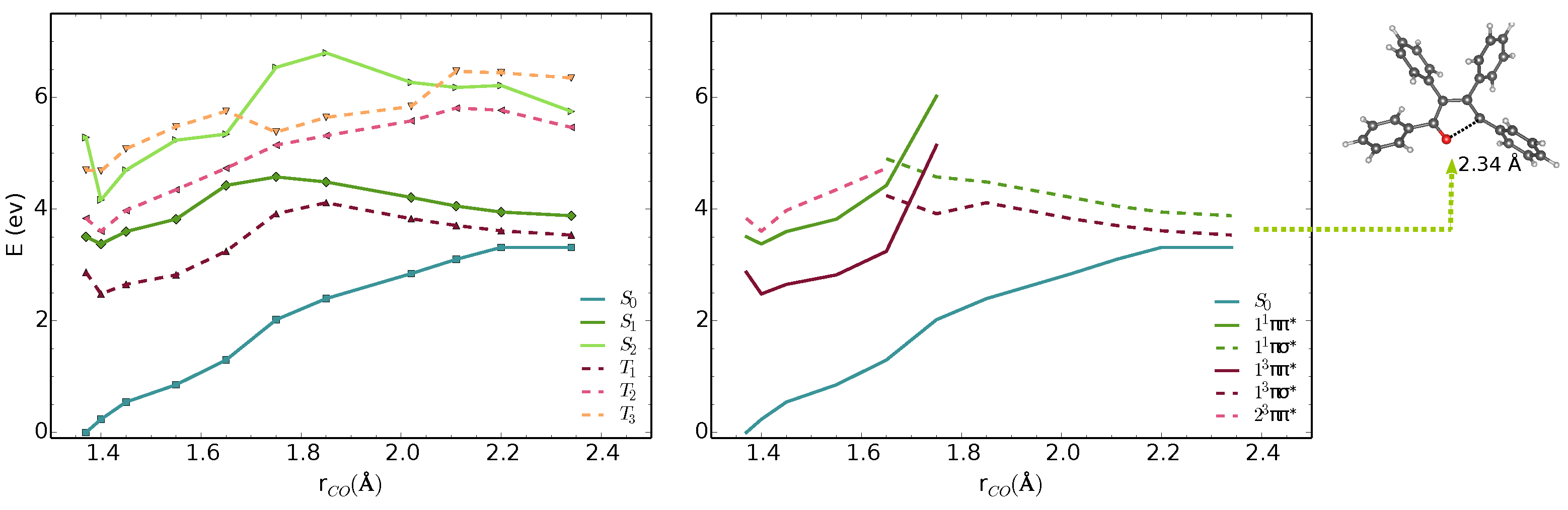
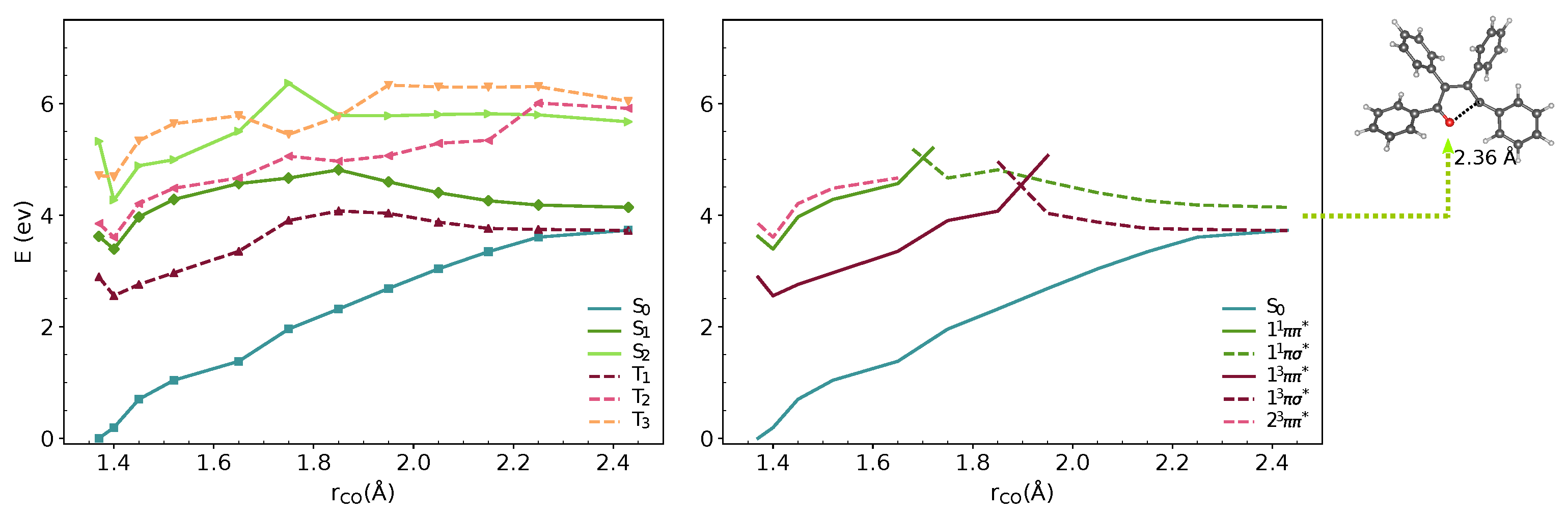
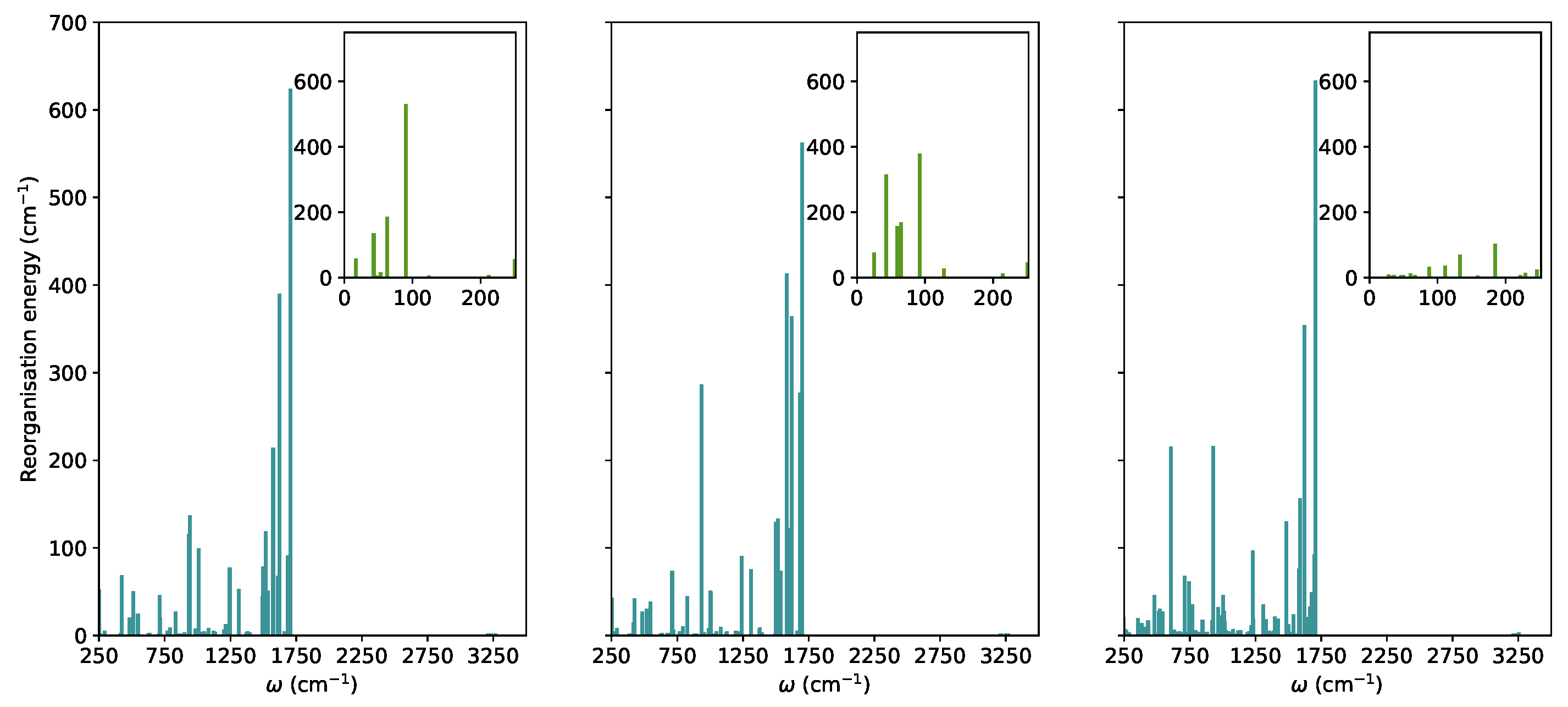
3.2. Nonradiative Relaxation Mechanisms

In this section, we explored the main molecule-centred nonradiative pathways processes in the vacuum and crystal. We first computed the Huang-Rhys factors and the reorganisation energies for S 1 to S 0 transitions projected on the normal modes (Figure 2).
In TPF, similar to other propeller-shaped systems (TPC and TPT) [9,10], the low-frequency vibrations are hindered by the crystal environment. The modes with ω < 250 cm 1 were considered as low-frequency modes. In the RIM model, it is normally assumed that low-frequency modes are the most important for nonradiative decay. For TPF, these vibrations correspond to collective motions of phenyl-rings with respect to the furan moiety. Their total contributions to the reorganisation energies in the vacuum, solution, and crystal were added showing a significant decrease when going from 952 cm 1 in the vacuum, 1100 cm 1 in THF to 302 cm 1 in the crystal.
According to the RIM model, this effect would lead to less efficient overlap between the vibrational wavefunctions of S 1 and S 0 and consequently a decrease of intramolecular nonradiative rates and enhancement of the emission quantum yields in the condensed phase. However, the experimental results show that fluorescence is quenched in the solid state. We explored in more detail the intramolecular pathways connecting the optimised critical points in the vacuum and crystal.
We analysed the minimal energy pathways driving the nonradiative decay. In both phases, the optimised S 1 –S 0 MECIs involve ring-opening and C-O bond breaking and occur at C-O distances in the range of 2.3–2.4 Å (Figure 3 and Figure 4). The potential energy profile connecting the FC region with the S 1 –S 0 MECI predicts the crossing of two diabatic states along the C-O stretching coordinate (Figure 3 and Figure 4). There is also a S 1 –T 1 crossing at a similar interatomic distance. In the FC region, S 1 has a π π * character with the electron density localised on the furan moiety and two of the phenyl substituents (Figure 6). This state crosses with a higher-lying π σ * state at ∼1.7 Å, both in vacuum and crystal. From the initially excited S 1 , the barrier to the π π * / π σ * crossing is ≈1.1 eV. Consequently, the S 1 –S 0 MECIs are classically inaccessible in both phases.
Because of the barrier, the system can remain trapped in the 1 1 π π * minimum. The 2 3 π π * / 1 1 π π * (T 2 /S 1 ) intersystem crossing competes with fluorescence from the bright π π * state. At this geometry, the  1 1 π π * state is quasi-degenerate with the 2 3 π π * state, which enhances the probability for the intersystem crossing. We computed the intersystem crossing rates ( k I S C ) for the 2 3 π π * / 1 1 π π * (T 2 /S 1 ) transition based on the Marcus-Levich-Jortner model (Equation (2)) in the vacuum and crystal. Because both states have π π * character, small values of SOCs are expected considering the El-Sayed rule. The values of S 1 | H S O | T 2 obtained with CASSCF(10,10)/6-31G(d) are 0.11 and 0.18 cm 1 in the gas phase and the crystal. The intersystem crossing rates are highly sensitive to small modulations of Δ E S T that varies significantly with the level of theory. We chose the TD-B3LYP/6-31G(d) value, because its better agreement with experimental emission energies and Δ E S T (Table 1).
Due to the large differences in their adiabatic energies, the calculated intersystem crossing rates for transition between S 1 and T 1 states are negligible. The predicted values of k I S C for the transition between T 2 and S 1 are 1.1  × 10 8 s 1 and 0.7  × 10 8 s 1 is the vacumm and solid state respectively (Table 2). After IC from T 2 , T 1 is populated and following vibrational relaxation the system can decay to S 0 since the T 1 –S 0 crossing is classically accessible.The analysis of the potential energy surfaces in both phases shows the access to the S 1 –S 0 conical intersection is hindered due to a barrier of more than 1 eV to the π σ * state. Deactivation through the triplet manifold is facilitated by the ISC in the FC region. However, due to the small values of SOCs, this process is relatively slow. The similar behaviour in both phases does not justify the differences in quantum yields in solution and the solid-state. In the next section, we discuss the effect of crystal environment and specific intermolecular interactions on nonradiative processes in TPF.

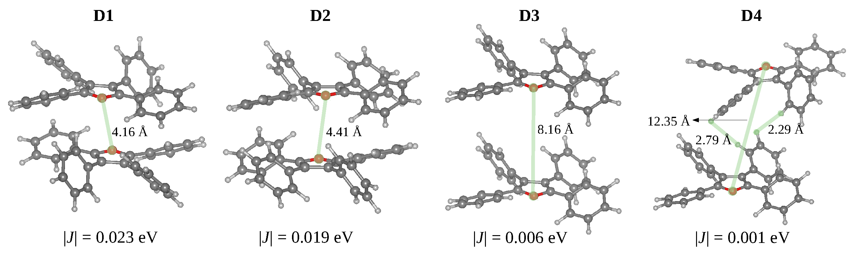
3.3. Crystal Structure: Intermolecular Interactions and Exciton Transport

In comparison to TPT [10], the TPF molecule features a more planar structure, i.e., at the FC point the side phenyl rings and furan rings form very small dihedral angles in the vacuum, solution and crystal, which is reflected a larger delocalisation of the HOMO and LUMO over these three rings. The phenyl rings attached to C2 and C3 atoms also define small dihedral angles with the furan ring. While in the TPT crystal, the close contact between phenyl rings is avoided by significant in-plane slipping of stacked dimers, in the TPF crystal the stacked dimers have face-to-tail orientation and in-plane slipping is relatively small in comparison to TPT.
From the optimised crystal structure, we extracted the dimers with distances between the centroids smaller than 10 Å using fromage. Considering that the oscillator strengths for the S 0 S 1 transitions are negligible and for the S 0 S 2 transitions are almost twice the values of the excitation in the isolated monomer, all dimers can be classified as H-dimers (Table 3). The stacked dimers (D1 and D2) with a face-to-tail arrangement have the shortest centroid distances. The O-O distances between adjacent layers in the TPF crystal (4.15 Å in D1 and 4.41 Å in D2 Figure 5) are significantly shorter compared with the S-S distances in TPT (6.05 Å), as a result of relatively small in-plane slipping in TPF. The D3 and D4 dimers feature larger centroid distances and short H..H and C-H.. π interactions.
The phenyl substituents do not allow strong π - π stacking interactions and effective exciton couplings. The dimers D1 and D2 display stacking between the furan rings with the largest excition couplings of 0.023 and 0.019 eV, respectively. These exciton couplings originate in π - π interactions between transition densities localised on furan and side phenyl rings. For the D3 and D4 dimers, the exciton couplings are very small (0.006 and 0.001 eV) due to the large spatial separation of S 1 transition densities localised on individual monomers.
Intermolecular processes, such as exciton hopping, compete with intramolecular relaxation mechanisms in molecular crystals. Shuai et al. have shown that regardless of the nature of the aggregation (J or H), the increase of exciton couplings enhances nonradiative decay rates [7]. We calculated exciton hopping rates ( ν i j ) between monomers using the Marcus model (Equation (3)). This model is valid in a weak coupling regime, when excitons are localised on individual monomers and transport happens through incoherent hopping, i.e., through exciton hopping events between single molecules. However, in the case when exciton is delocalised over two or more monomer units, this approximation usually predicts overestimated hopping rates [47]. Our calculations show that after relaxation to S 1 , the electron density localises releasing ≈ 0.4 eV (Figure 6).
According to the Marcus model, the barrier for exciton hopping is approximately λ / 4 , where λ is the reorganisation energy for S 1 to S 0 transition [48]. For the TPF crystal, the exciton couplings (<0.023 eV) are much smaller in comparison with the reorganisation energy ( λ = 0.7 eV), and the exciton transfer is expected to take place in the incoherent regime. The exciton hopping rate in TPF between molecules in the dimer D1, computed based on Equation (4) is 1.17  × 10 10 s 1 and between molecules in the dimer D2 7.98  × 10 9 s 1 . Thermal fluctuations induced by molecular vibrations can modulate the exciton coupling magnitudes and exciton hopping rates.
In comparison with TPT, the TPF crystal features significantly lower reorganisation energies and slightly larger exciton couplings (Table 4). Both effects result in ∼60 times faster exciton hopping in TPF (1.17  × 10 10 in TPF vs. 0.02  × 10 10 s 1 in TPT). In comparison, the exciton hopping is two orders of magnitude slower in the TPT crystal (Table 4). We have previously shown that the main nonradiative pathway in TPT are localised on monomers and are associated with efficient intersystem crossing channels [10]. Similar nonradiative pathways including internal conversion and intersystem crossing are not energetically accessible in TPF, which indicate a significant role of intermolecular exciton mechanisms in the excited state decay of this crystal.

4. Conclusions

In contrast to several propeller-shaped systems that show enhanced emission in the solid-state, TPF exhibits aggregation quenching. This work highlights the interplay between intramolecular and intermolecular factors in the excited state dynamics of propeller-shaped molecules in the crystalline phase. When the nature of the central atom is modified (Figure 1), moving from C (TPC), to S (TPT) and O (TPF), the main nonradiative pathway changes from puckering to bond breaking [9,10]. Additionally for TPT and TPF, triplets are essential in the excited-state mechanisms.
In the vacuum and solid-state, the analysis potential energies surfaces of TPF shows that the C-O stretching leads to crossings between the excited and ground states. Due to the existence of a barrier of ∼1 eV to reach the π π * / π σ * crossing, the S 0 –S 1 is inaccessible in both solution and the solid-state. From the S 1 minimum, it is possible to populate T 2 through ISC. Following IC from T 2 , T 1 is populated and since the S 0 –T 1 crossing is classically accessible, (TPF) can decay nonradiatively through the S 0 –T 1 crossing. The slight differences in the potential energy surfaces in the vacuum and solid-state do not justify the significant differences in the experimental quantum yields and the emission quenching in the solid-state.
For both, TPT and TPF, nonradiative decay pathways involving triplets are accessible in the solid-state, depleting the population of singlets and contributing to a smaller quantum yield in comparison to TPC. This is the reason for the weak AIE in TPT, however, TPF displays quenching in the solid-state. Our calculations indicate that the reason behind the different behaviour of these systems is the activation of intermolecular nonradiative processes in TPF.
Because TPF has a more planar structure, the crystal packing is more compact enabling more effective interactions between the central aromatic rings. The exciton couplings are slightly larger in TPF. Additionally, reorganisation energies are smaller for TPF and the exciton hopping rates are much faster in comparison to TPT. These transport events will contribute to nonradiative pathways not available in other propeller-shaped systems.

Supplementary Materials

The following supporting information can be downloaded, S1: Geometries, S2: The CASSCF active space orbitals, Figure S1: The CASSCF(10,10)/6-31G(d) orbitals used in the S 0 /S 1 and S 0 /T 1 minimum energy crossing point optimisations and MS-3-CASPT2/SA-3-CASSCF(10,10)/6-31G(d) single point computations along the optimised pathways in the vacuum and crystal.

Author Contributions

L.S. and R.C.-O. designed the work and interpreted the results. L.S. performed the calculations and analysed the data. Both authors contributed to writing the paper. All authors have read and agreed to the published version of the manuscript.

Funding

Engineering and Physical Sciences Research Council (EPSRC, EP/R029385/1, EP/L000202/1, EP/T022213/1) and Leverhulme Trust (RPG-2019-122).

Data Availability Statement

The optimised geometries in the vacuum and the crystal phase can be found in a public repository: https://github.com/Crespo-Otero-group/TPF_data.

Acknowledgments

This research has been supported by the EPSRC (EP/R029385/1) and Leverhulme Trust (RPG-2019-122). We utilized Queen Mary’s Apocrita HPC facility, supported by QMUL Research-IT and the ARCHER UK National Supercomputing Service (EP/L000202/1) via the Materials Chemistry Consortium and the Molecular Modelling Hub for computational resources, MMM Hub, which is partially funded by EPSRC (EP/T022213/1).

Conflicts of Interest

The authors declare no conflict of interest.

References

  1. Shi, J.; Aguilar Suarez, L.E.; Yoon, S.J.; Varghese, S.; Serpa, C.; Park, S.Y.; Lüer, L.; Roca-Sanjuán, D.; Milián-Medina, B.; Gierschner, J. Solid State Luminescence Enhancement in π-Conjugated Materials: Unraveling the Mechanism beyond the Framework of AIE/AIEE. J. Phys. Chem. C 2017, 121, 23166–23183. [Google Scholar] [CrossRef]
  2. Peng, X.L.; Ruiz-Barragan, S.; Li, Z.S.; Li, Q.S.; Blancafort, L. Restricted Access to a Conical Intersection to Explain Aggregation Induced Emission in Dimethyl Tetraphenylsilole. J. Mater. Chem. C 2016, 4, 2802–2810. [Google Scholar] [CrossRef]
  3. Crespo-Otero, R.; Li, Q.; Blancafort, L. Exploring Potential Energy Surfaces for Aggregation-Induced Emission—From Solution to Crystal. Chem. Asian J. 2019, 14, 700–714. [Google Scholar] [CrossRef] [Green Version]
  4. Shen, P.; Zhuang, Z.; Zhao, Z.; Tang, B.Z. AIEgens based on main group heterocycles. J. Mater. Chem. C 2018, 6, 11835–11852. [Google Scholar] [CrossRef]
  5. Dommett, M.; Rivera, M.; Crespo-Otero, R. How Inter- and Intramolecular Processes Dictate Aggregation-Induced Emission in Crystals Undergoing Excited-State Proton Transfer. J. Phys. Chem. Lett. 2017, 8, 6148–6153. [Google Scholar] [CrossRef] [PubMed]
  6. Dommett, M.; Rivera, M.; Smith, M.T.H.; Crespo-Otero, R. Molecular and crystalline requirements for solid state fluorescence exploiting excited state intramolecular proton transfer. J. Mater. Chem. C 2020, 8, 2558–2568. [Google Scholar] [CrossRef]
  7. Li, W.; Zhu, L.; Shi, Q.; Ren, J.; Peng, Q.; Shuai, Z. Excitonic coupling effect on the nonradiative decay rate in molecular aggregates: Formalism and application. Chem. Phys. Lett. 2017, 683, 507–514. [Google Scholar] [CrossRef]
  8. Yu, G.; Yin, S.; Liu, Y.; Chen, J.; Xu, X.; Sun, X.; Ma, D.; Zhan, X.; Peng, Q.; Shuai, Z.; et al. Structures, Electronic States, Photoluminescence, and Carrier Transport Properties of 1,1-Disubstituted 2,3,4,5-Tetraphenylsiloles. J. Am. Chem. Soc. 2005, 127, 6335–6346. [Google Scholar] [CrossRef] [PubMed]
  9. Stojanović, L.; Crespo-Otero, R. Understanding Aggregation Induced Emission in a Propeller-Shaped Blue Emitter. ChemPhotoChem 2019, 3, 907–915. [Google Scholar] [CrossRef]
  10. Stojanović, L.; Crespo-Otero, R. Aggregation-Induced Emission in the Tetraphenylthiophene Crystal: The Role of Triplet States. J. Phys. Chem. C 2020, 124, 17752–17761. [Google Scholar] [CrossRef]
  11. Nie, H.; Hu, K.; Cai, Y.; Peng, Q.; Zhao, Z.; Hu, R.; Chen, J.; Su, S.J.; Qin, A.; Tang, B.Z. Tetraphenylfuran: Aggregation-induced emission or aggregation-caused quenching? Mater. Chem. Front. 2017, 1, 1125–1129. [Google Scholar] [CrossRef]
  12. Gu, Y.; Li, N.; Shao, G.; Wang, K.; Zou, B. Mechanism of Different Piezoresponsive Luminescence of 2,3,4,5-Tetraphenylthiophene and 2,3,4,5-Tetraphenylfuran: A Strategy for Designing Pressure-Induced Emission Enhancement Materials. J. Phys. Chem. Lett. 2020, 11, 678–682. [Google Scholar] [CrossRef]
  13. Liu, X.; Li, M.; Liu, M.; Yang, Q.; Chen, Y. From Tetraphenylfurans to Ring-Opened (Z)-1,4-Enediones: ACQ Fluorophores versus AIEgens with Distinct Responses to Mechanical Force and Light. Chem. Eur. J. 2018, 24, 13197–13204. [Google Scholar] [CrossRef] [PubMed]
  14. Wang, J.; Gu, X.; Zhang, P.; Huang, X.; Zheng, X.; Chen, M.; Feng, H.; Kwok, R.T.K.; Lam, J.W.Y.; Tang, B.Z. Ionization and Anion-π+ Interaction: A New Strategy for Structural Design of Aggregation-Induced Emission Luminogens. J. Am. Chem. Soc. 2017, 139, 16974–16979. [Google Scholar] [CrossRef] [PubMed]
  15. Chai, J.D.; Head-Gordon, M. Long-range corrected hybrid density functionals with damped atom-atom dispersion corrections. Phys. Chem. Chem. Phys. 2008, 10, 6615–6620. [Google Scholar] [CrossRef] [PubMed] [Green Version]
  16. Bauernschmitt, R.; Ahlrichs, R. Treatment of electronic excitations within the adiabatic approximation of time dependent density functional theory. Chem. Phys. Lett. 1996, 256, 454–464. [Google Scholar] [CrossRef]
  17. Casida, M.E.; Jamorski, C.; Casida, K.C.; Salahub, D.R. Molecular excitation energies to high-lying bound states from time-dependent density-functional response theory: Characterization and correction of the time-dependent local density approximation ionization threshold. J. Chem. Phys. 1998, 108, 4439–4449. [Google Scholar] [CrossRef]
  18. Stratmann, E.R.; Scuseria, G.E.; Frisch, M.J. An efficient implementation of time-dependent density-functional theory for the calculation of excitation energies of large molecules. J. Chem. Phys. 1998, 109, 8218–8224. [Google Scholar] [CrossRef]
  19. Caillie, C.V.; Amos, R.D. Geometric derivatives of excitation energies using SCF and DFT. Chem. Phys. Lett. 1999, 308, 249–255. [Google Scholar] [CrossRef]
  20. Furche, F.; Ahlrichs, R. Adiabatic time-dependent density functional methods for excited state properties. J. Chem. Phys. 2002, 117, 7433–7447. [Google Scholar] [CrossRef]
  21. Frisch, M.J.; Trucks, G.W.; Schlegel, H.B.; Scuseria, G.E.; Robb, M.A.; Cheeseman, J.R.; Scalmani, G.; Barone, V.; Petersson, G.A.; Nakatsuji, H.; et al. Gaussian 16 Revision A.03; Gaussian Inc.: Wallingford, CT, USA, 2016. [Google Scholar]
  22. Christiansen, O.; Koch, H.; Jørgensen, P. The second-order approximate coupled cluster singles and doubles model CC2. Chem. Phys. Lett. 1995, 243, 409–418. [Google Scholar] [CrossRef]
  23. Hättig, C.; Köhn, A. Transition moments and excited-state first-order properties in the coupled-cluster model CC2 using the resolution-of-the-identity approximation. J. Chem. Phys. 2002, 117, 6939–6951. [Google Scholar] [CrossRef]
  24. Hättig, C. Geometry optimizations with the coupled-cluster model CC2 using the resolution-of-the-identity approximation. J. Chem. Phys. 2003, 118, 7751–7761. [Google Scholar] [CrossRef]
  25. Köhn, A.; Hättig, C. Analytic gradients for excited states in the coupled-cluster model CC2 employing the resolution-of-the-identity approximation. J. Chem. Phys. 2003, 119, 5021–5036. [Google Scholar] [CrossRef]
  26. Roos, B.O.; Sadlej, A.J.; Malmqvist, P.Å.; Andersson, K.; Wolinski, K. Second-order perturbation theory with a CASSCF reference function. J. Phys. Chem. 1990, 94, 5483–5488. [Google Scholar] [CrossRef]
  27. Andersson, K.; Malmqvist, P.Å.; Roos, B.O. Second-order perturbation theory with a complete active space self-consistent field reference function. J. Chem. Phys. 1992, 96, 1218–1226. [Google Scholar] [CrossRef]
  28. Vancoillie, S.; Delcey, M.G.; Lindh, R.; Vysotskiy, V.; Malmqvist, P.Å.; Veryazov, V. Parallelization of a multiconfigurational perturbation theory. J. Comput. Chem. 2013, 34, 1937–1948. [Google Scholar] [CrossRef]
  29. Roos, B.O.; Taylor, P.R.; Siegbahn, P.E.M. A complete active space SCF method (CASSCF) using a density matrix formulated super-CI approach. Chem. Phys. 1980, 48, 157–173. [Google Scholar] [CrossRef]
  30. Maeda, S.; Ohno, K.; Morokuma, K. Updated Branching Plane for Finding Conical Intersections without Coupling Derivative Vectors. J. Chem. Theory Comput. 2010, 6, 1538–1545. [Google Scholar] [CrossRef]
  31. Aquilante, F.; Autschbach, J.; Carlson, R.K.; Chibotaru, L.F.; Delcey, M.G.; De Vico, L.; Fdez Galván, I.; Ferré, N.; Frutos, L.M.; Gagliardi, L.; et al. Molcas 8: New capabilities for multiconfigurational quantum chemical calculations across the periodic table. J. Comput. Chem. 2016, 37, 506–541. [Google Scholar] [CrossRef] [Green Version]
  32. TURBOMOLE V7.0 2015, a Development of University of Karlsruhe and Forschungszentrum Karlsruhe GmbH, 1989–2007, TURBOMOLE GmbH, Since 2007. Available online: http://www.turbomole.com (accessed on 10 December 2021).
  33. Giannozzi, P.; Baroni, S.; Bonini, N.; Calandra, M.; Car, R.; Cavazzoni, C.; Ceresoli, D.; Chiarotti, G.L.; Cococcioni, M.; Dabo, I.; et al. QUANTUM ESPRESSO: A modular and open-source software project for quantum simulations of materials. J. Phys. Condens. Matter 2009, 21, 395–502. [Google Scholar] [CrossRef]
  34. Dapprich, S.; Komaromi, I.; Suzie Byun, K.; Morokuma, K.; Frisch, M.J. A new ONIOM implementation in Gaussian98. Part I. The calculation of energies, gradients, vibrational frequencies and electric field derivatives. J. Mol. Struct. Theochem 1999, 461–462, 121. [Google Scholar] [CrossRef]
  35. Chung, L.W.; Sameera, W.M.; Ramozzi, R.; Page, A.J.; Hatanaka, M.; Petrova, G.P.; Harris, T.V.; Li, X.; Ke, Z.; Liu, F.; et al. The ONIOM Method and Its Applications. Chem. Rev. 2015, 115, 5678–5796. [Google Scholar] [CrossRef] [PubMed] [Green Version]
  36. Merz, K.M.; Cornell, W.D.; Kollman, P.A.; Ferguson, D.M.; Cieplak, P.; Caldwell, J.W.; Bayly, C.I.; Gould, I.R.; Spellmeyer, D.C.; Fox, T. A Second Generation Force Field for the Simulation of Proteins, Nucleic Acids, and Organic Molecules. J. Am. Chem. Soc. 2005, 117, 5179–5197. [Google Scholar] [CrossRef] [Green Version]
  37. Rivera, M.; Dommett, M.; Crespo-Otero, R. ONIOM(QM:QM’) Electrostatic Embedding Schemes for Photochemistry in Molecular Crystals. J. Chem. Theory Comput. 2019, 15, 2504–2516. [Google Scholar] [CrossRef]
  38. Rivera, M.; Dommett, M.; Sidat, A.; Rahim, W.; Crespo-Otero, R. fromage: A library for the study of molecular crystal excited states at the aggregate scale. J. Comput. Chem. 2020. [Google Scholar] [CrossRef]
  39. Aradi, B.; Hourahine, B.; Frauenheim, T. DFTB+, a Sparse Matrix-Based Implementation of the DFTB Method. J. Phys. Chem. A 2007, 111, 5678–5684. [Google Scholar] [CrossRef]
  40. Elstner, M.; Porezag, D.; Jungnickel, G.; Elsner, J.; Haugk, M.; Frauenheim, T.; Suhai, S.; Seifert, G. Self-consistent-charge density-functional tight-binding method for simulations of complex materials properties. Phys. Rev. B 1998, 58, 7260–7268. [Google Scholar] [CrossRef]
  41. Marcus, R.A. Electron transfer reactions in chemistry. Theory and experiment. Rev. Mod. Phys. 1993, 65, 599–610. [Google Scholar] [CrossRef] [Green Version]
  42. Levich, V.G.; Dogonadze, R.R. Theory of non-radiation electron transitions from ion to ion in solutions. Dokl. Akad. Nauk SSSR 1959, 124, 123–126. [Google Scholar]
  43. Levich, V.G. Present state of the theory of oxidation-reduction in solution (bulk and electrode reactions). Adv. Electrochem. Electrochem. Eng. 1966, 4, 249–371. [Google Scholar]
  44. Jortner, J. Temperature dependent activation energy for electron transfer between biological molecules. J. Chem. Phys. 1976, 64, 4860–4867. [Google Scholar] [CrossRef]
  45. Reimers, J.R. A practical method for the use of curvilinear coordinates in calculations of normal-mode-projected displacements and duschinsky rotation matrices for large molecules. J. Chem. Phys. 2001, 115, 9103–9109. [Google Scholar] [CrossRef]
  46. Aragó, J.; Troisi, A. Dynamics of the excitonic coupling in organic crystals. Phys. Rev. Lett. 2015, 114, 1–5. [Google Scholar] [CrossRef] [PubMed]
  47. Fornari, R.P.; Aragó, J.; Troisi, A. Exciton Dynamics in Phthalocyanine Molecular Crystals. J. Phys. Chem. C 2016, 120, 7987–7996. [Google Scholar] [CrossRef] [Green Version]
  48. Aragó, J.; Troisi, A. Regimes of Exciton Transport in Molecular Crystals in the Presence of Dynamic Disorder. Adv. Funct. Mater. 2015, 26, 2316–2325. [Google Scholar] [CrossRef]
Figure 1. Structures of propeller-shaped molecules with different emissive response.
Molecules 27 00522 g001
Figure 2. The reorganization energies for the relaxation from the S 1 state in TPF computed based on the TD- ω B97XD/6-31G(d) normal modes and energies in the vacuum, solution, and crystal (from left to right).
Molecules 27 00522 g002
Figure 3. MS-3-CASPT2/CASSCF(10,10)/6-31G(d) energies of S 0 –S 2 and T 1 –T 3 states along interpolated pathway between FC point, S 1 minimum and S 1 –S 0 MECI geometry in vacuum. The states are shown in adiabatic (left) and diabatic representation (right). The diabatic representation was obtained by connecting the excited states corresponding to the same type of transitions along the pathway.
Molecules 27 00522 g003
Figure 4. MS-3-CASPT2/CASSCF(10,10)/6-31G(d) energies of S 0 –S 2 and T 1 –T 3 states along interpolated pathway between FC point, S 1 minimum and S 1 –S 0 MECI geometry in crystal. The states are shown in adiabatic (left) and diabatic representation (right). The diabatic representation was obtained by connecting the excited states corresponding to the same type of transitions along the pathway.
Molecules 27 00522 g004
Figure 5. Structures of dimers in the TPF showing closest intermolecular contacts (Å) and absolute values of the exciton couplings (in eV).
Molecules 27 00522 g005
Figure 6. The TD-B3LYP/6-31G(d) density difference of the S 1 state at its minimum geometry in the D1 dimer of TPF obtained from QM(TD-B3LYP)/QM’(DFTB) optimisations.
Molecules 27 00522 g006
Table 1. Vertical absorption and emission energies and oscillator strengths (in parentheses) of the S 1 state of TPF in the vacuum, solution of THF, and crystal environment.
Energy (eV)
Vacuum/SolutionCrystal
AbsorptionEmissionAbsorptionEmission
RI-CC2/aug-cc-pVDZ4.10 (0.58)3.45 (0.71)--
TD-B3LYP/6-31G(d)3.72 (0.47)3.16 (0.50)3.72 (0.41)3.19 (0.43)
TD- ω B97X-D/6-31G(d)4.26 (0.51)3.47 (0.60)4.26 (0.49)3.49 (0.52)
TD- ω B97X-D/6-31G(d)/PCM4.19 (0.63)3.19 (0.89)--
MS-2-CASPT2/6-31G(d)3.503.143.613.20
Experimental [11]3.793.24-3.24
Table 2. Experimental values of fluorescence quantum yield ( Φ f ), radiative lifetimes ( τ r in ns), fluorescence rates ( k r e x p in 10 8 s 1 ), nonradiative rates ( k n r in 10 8 s 1 ), and computed fluorescence rates computed based on TD- ω B97X-D/6-31G(d) excitations ( k r E i n in 10 8 s 1 ) and intersystem crossing rates computed based on TD-B3LYP/6-31G(d) excitations ( k I S C M L J in 10 8 s 1 ).
SolutionCrystal
Experimental [11]
Φ r 0.400.01
τ r 0.680.06
k r 5.880.67
k n r 8.841.66 × 10 2
Predicted
k r E i n 3.933.89
k I S C M L J 1.10.7
Table 3. Excitation energies (E in eV), oscillator strengths (f) of monomer and relevant dimers and exciton coupling values (J in eV) between units in dimers isolated from TPF crystal.
StructureStateEf|J|
Monomer S 1 ( π π * )3.94340.72-
D1 S 1 ( π π * )3.90770.000.023
S 2 ( π π * )3.95441.30
D2 S 1 ( π π * )3.92090.000.019
S 2 ( π π * )3.96051.31
D3 S 1 ( π π * )3.93770.000.006
S 2 ( π π * )3.94951.40
D4 S 1 ( π π * )3.94220.000.001
S 2 ( π π * )3.94371.42
Table 4. Reorganisation energies in the crystal ( λ c r in eV), exciton couplings ( J i j in eV) for the dimer with smaller centroid distances, exciton hopping ( ν i j in 10 10 s 1 ) in TPF and TPT. V i are the values of Voronoi volumes of the crystals computed with fromage.
Crystal λ cr J ij V i ν ij
TPF0.700.0231.421.17
TPT1.000.0151.350.02
Publisher’s Note: MDPI stays neutral with regard to jurisdictional claims in published maps and institutional affiliations.

