
The Impact of Filler Geometry on Polylactic Acid-Based Sustainable Polymer Composites

 , ,
, ,  and
and 
Abstract
1. Introduction
2. Experimental
2.1. Materials
2.2. Sample Preparation
2.3. Methods
3. Results and Discussion
4. Conclusions
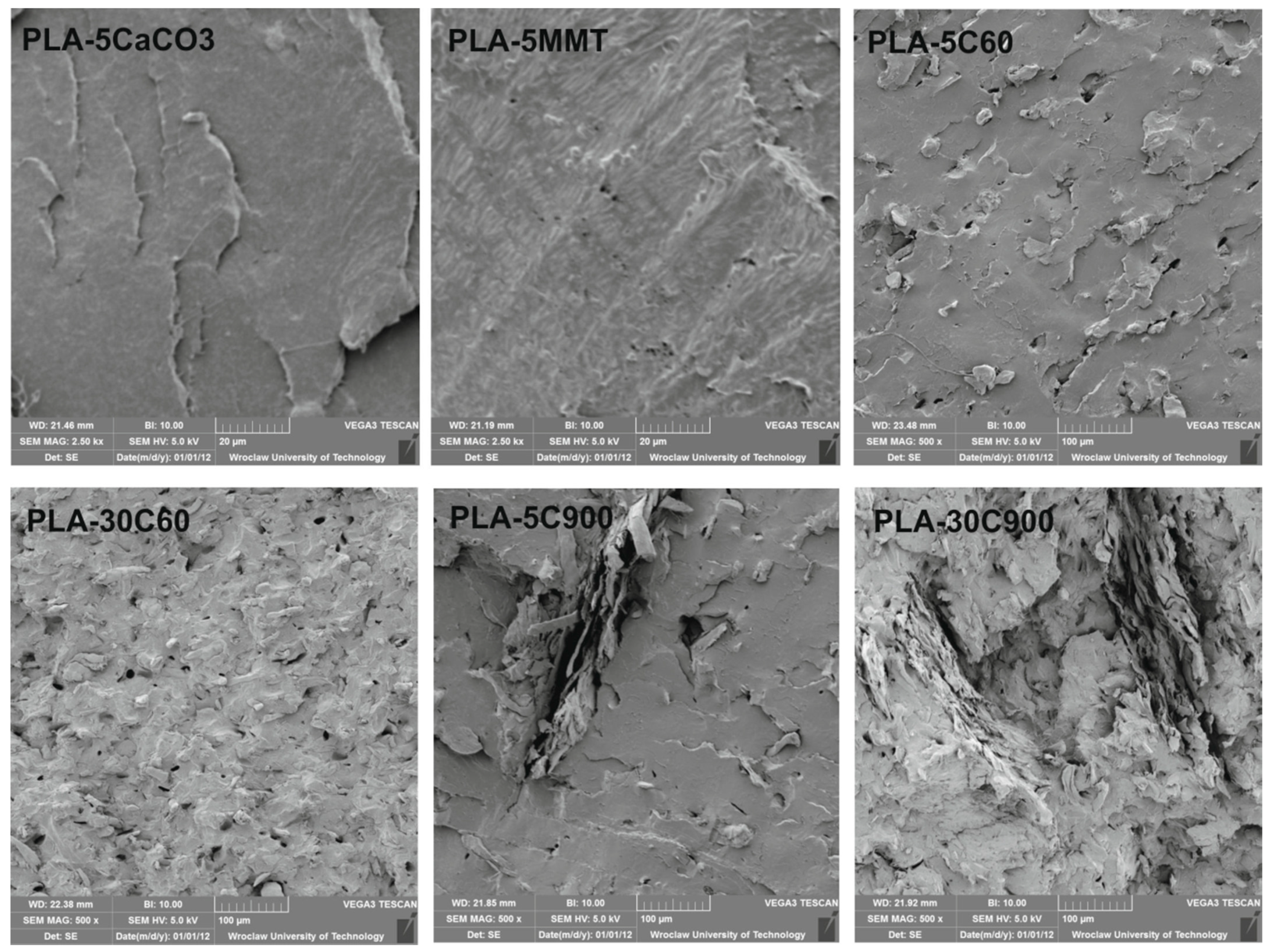
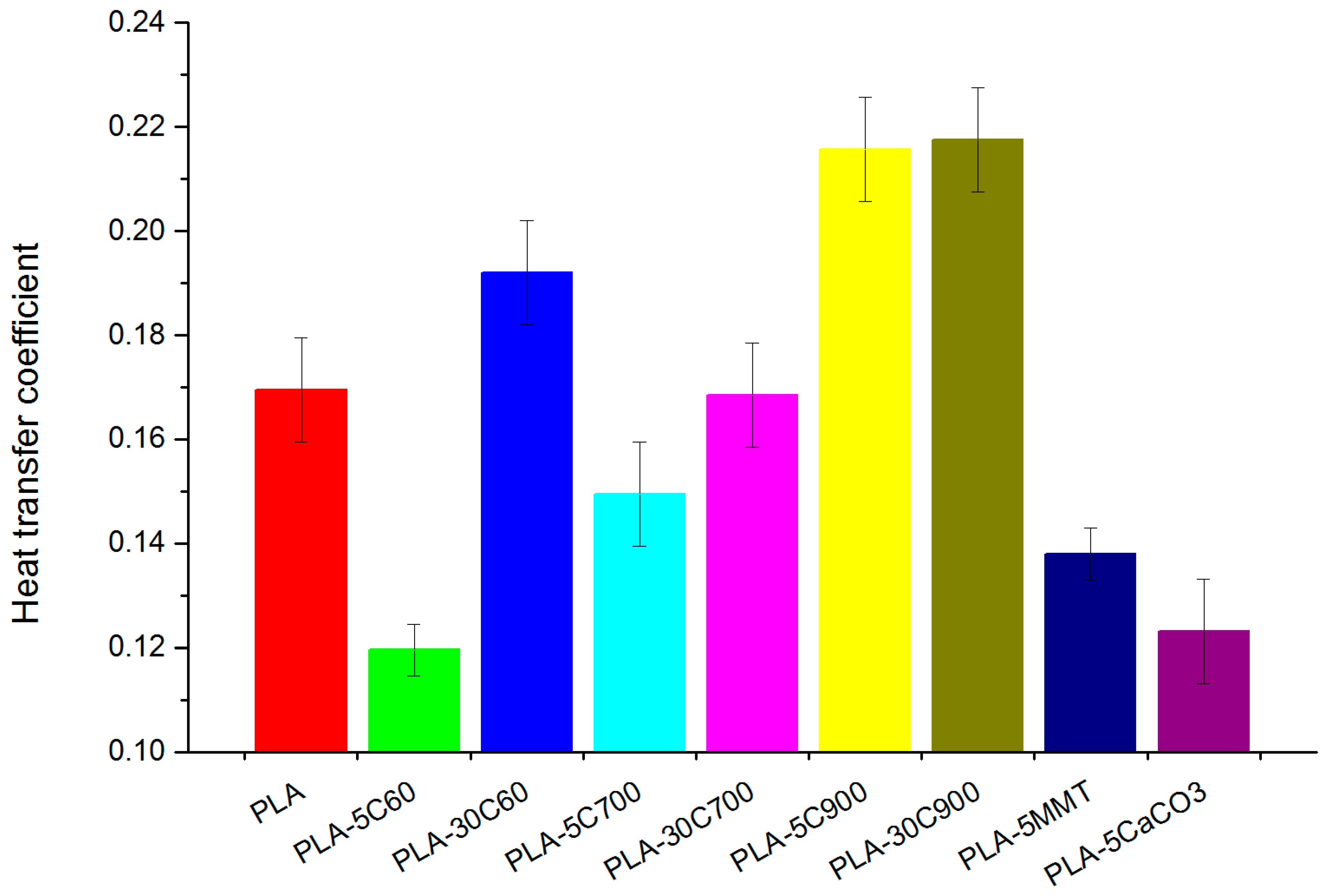
- Different filler types influence on polylactide acid matrix has been presented. The results obtained in this study showed that the aspect ratio of an introduced filler plays a key role in the material end properties.
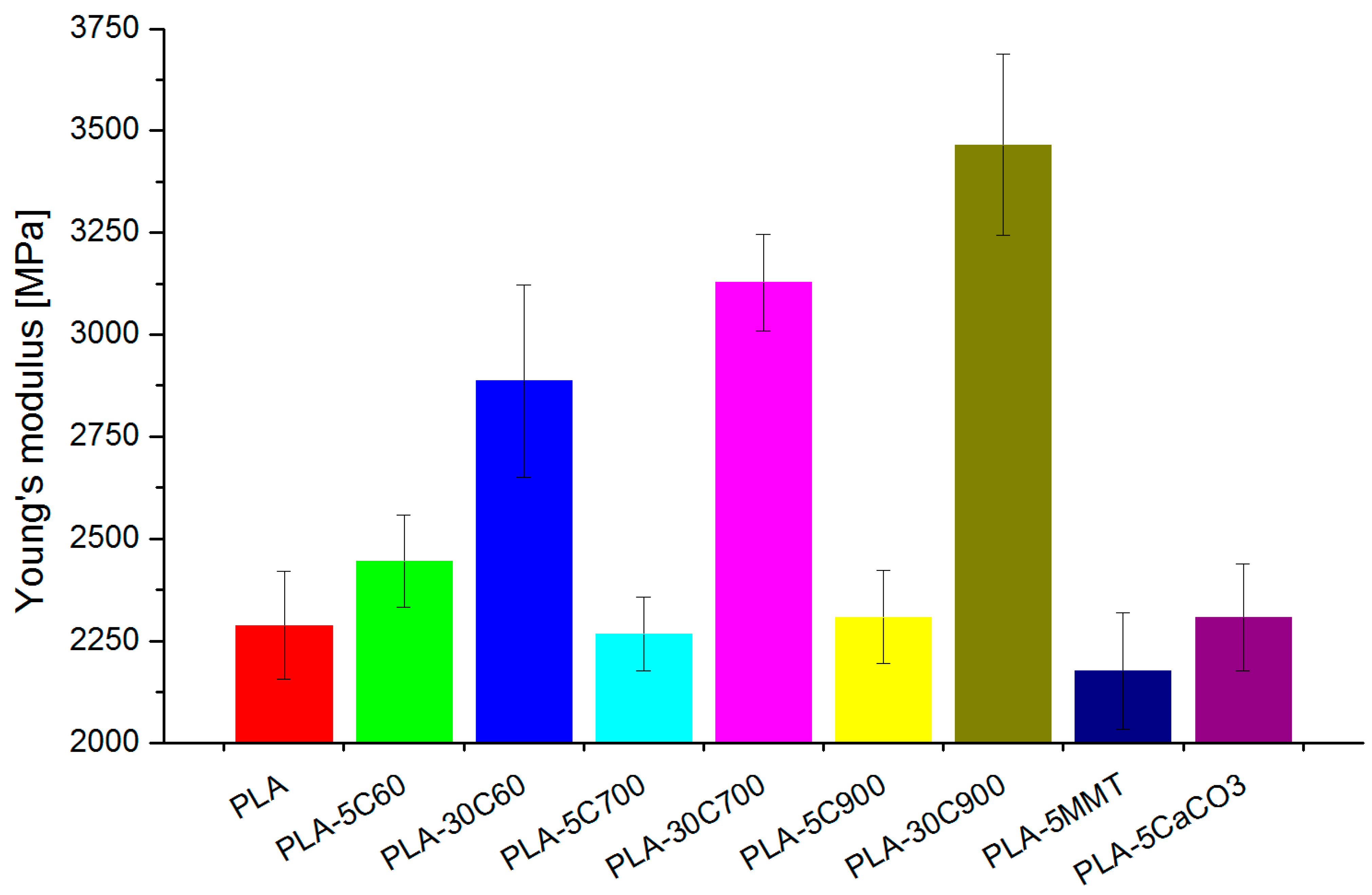
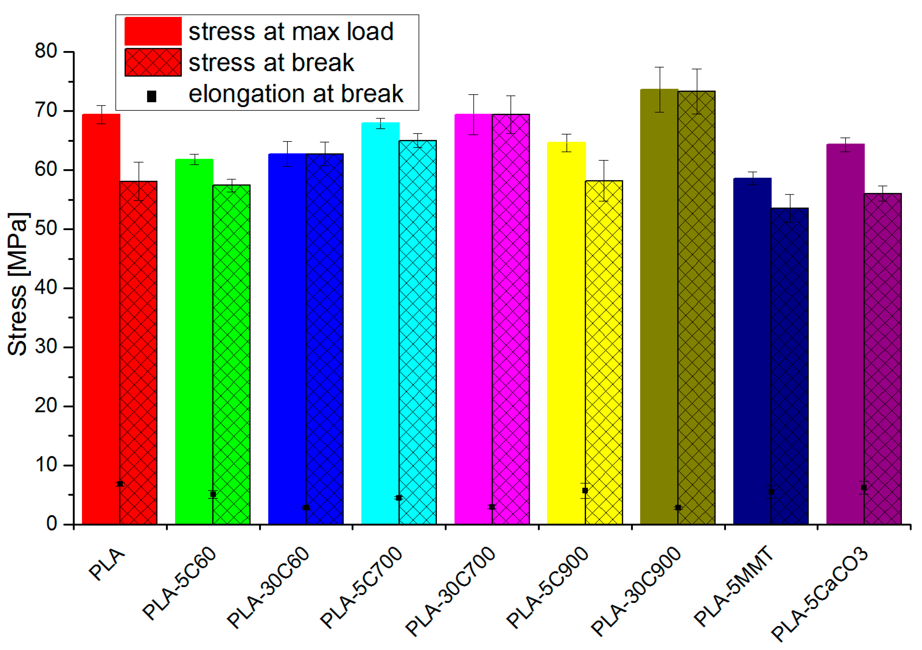
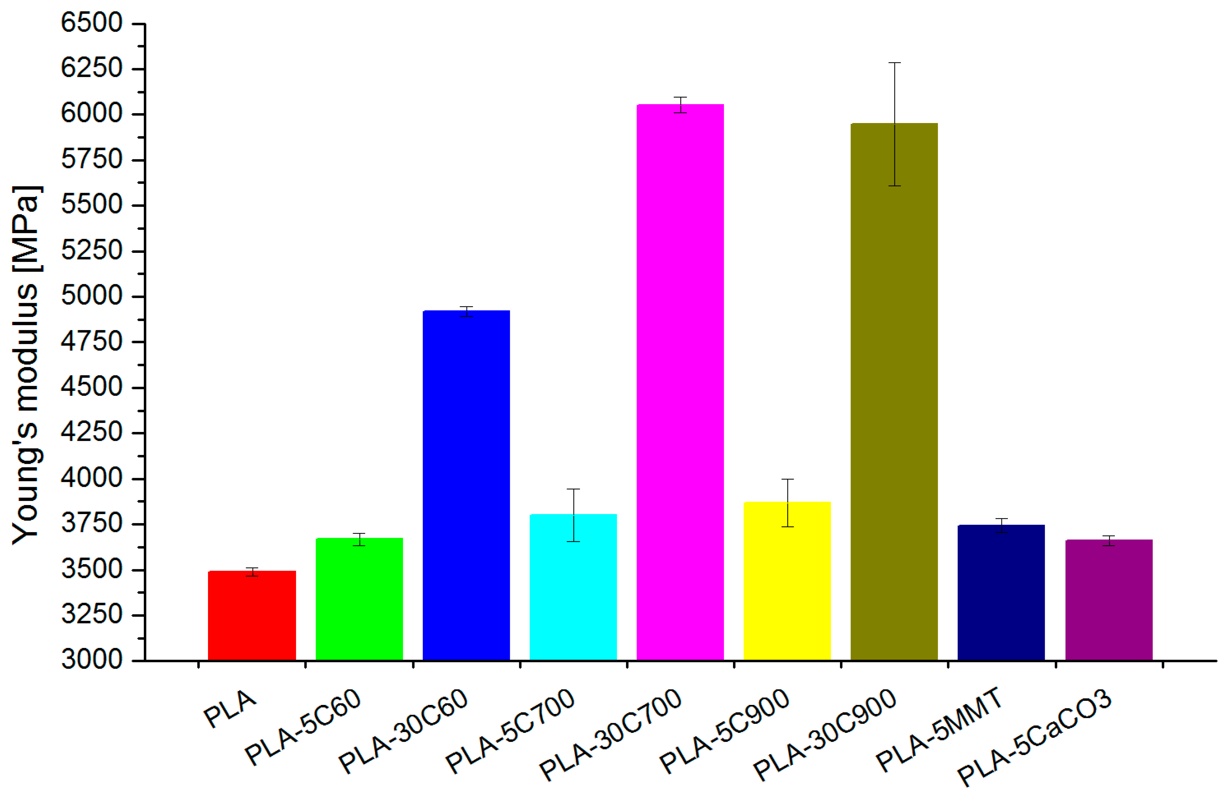
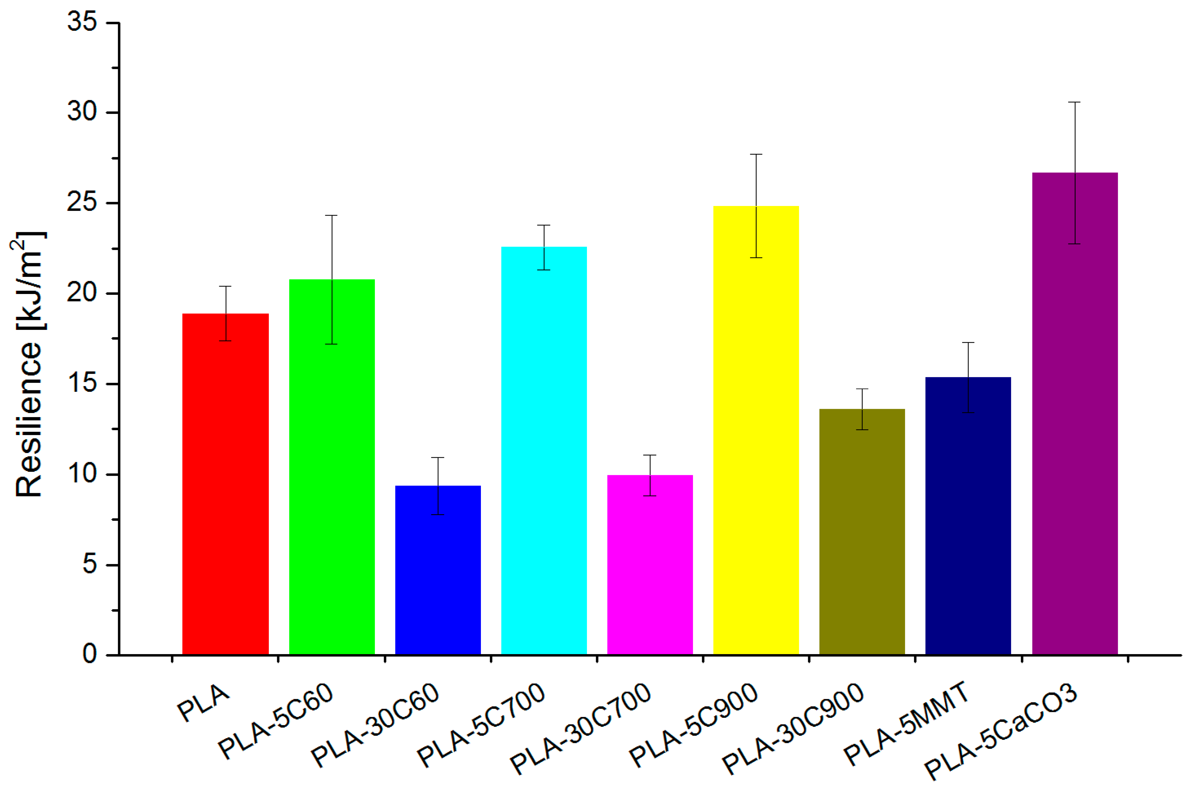
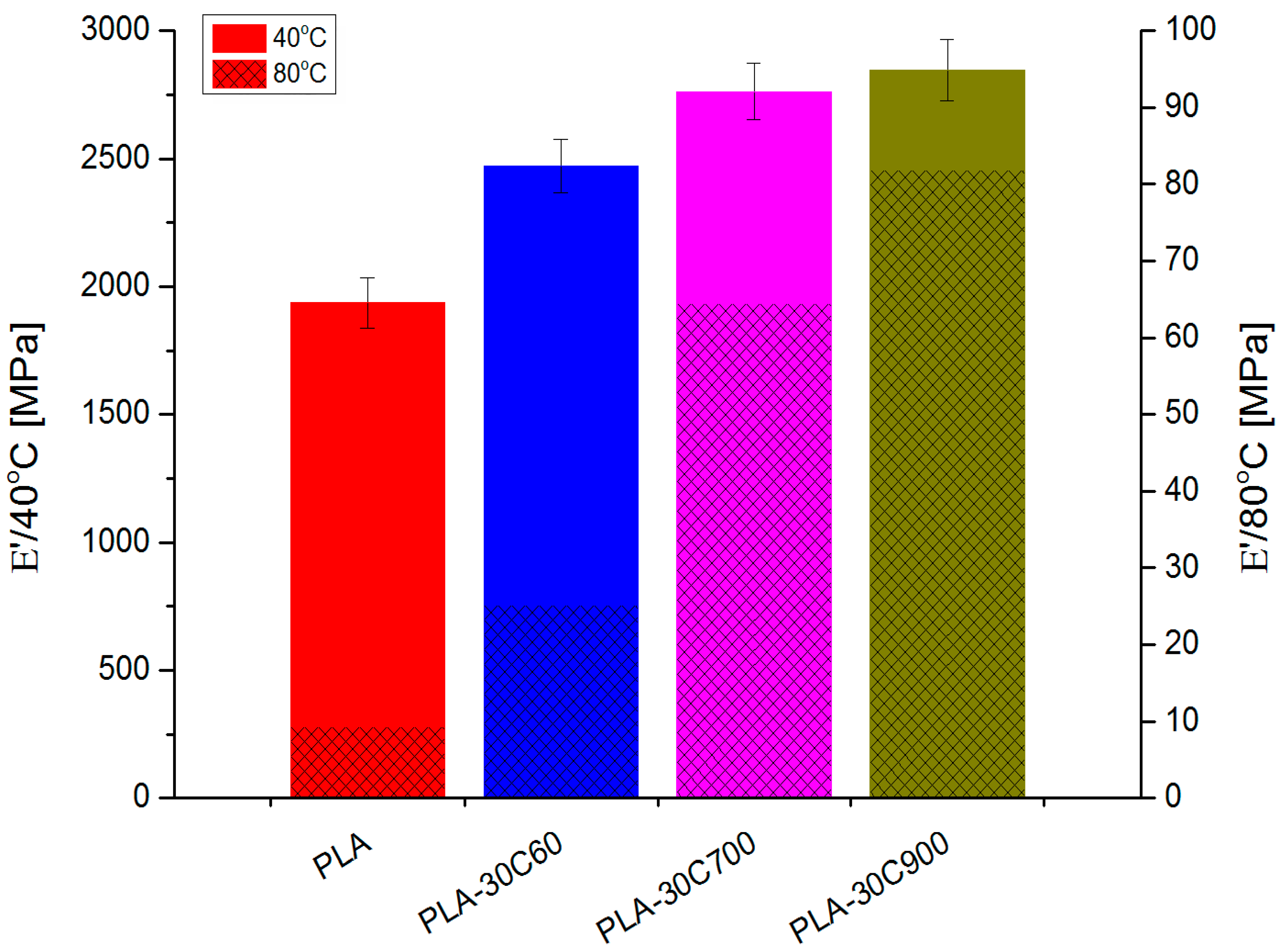
- Mechanical properties are highly affected by the filler loading and fibre length.
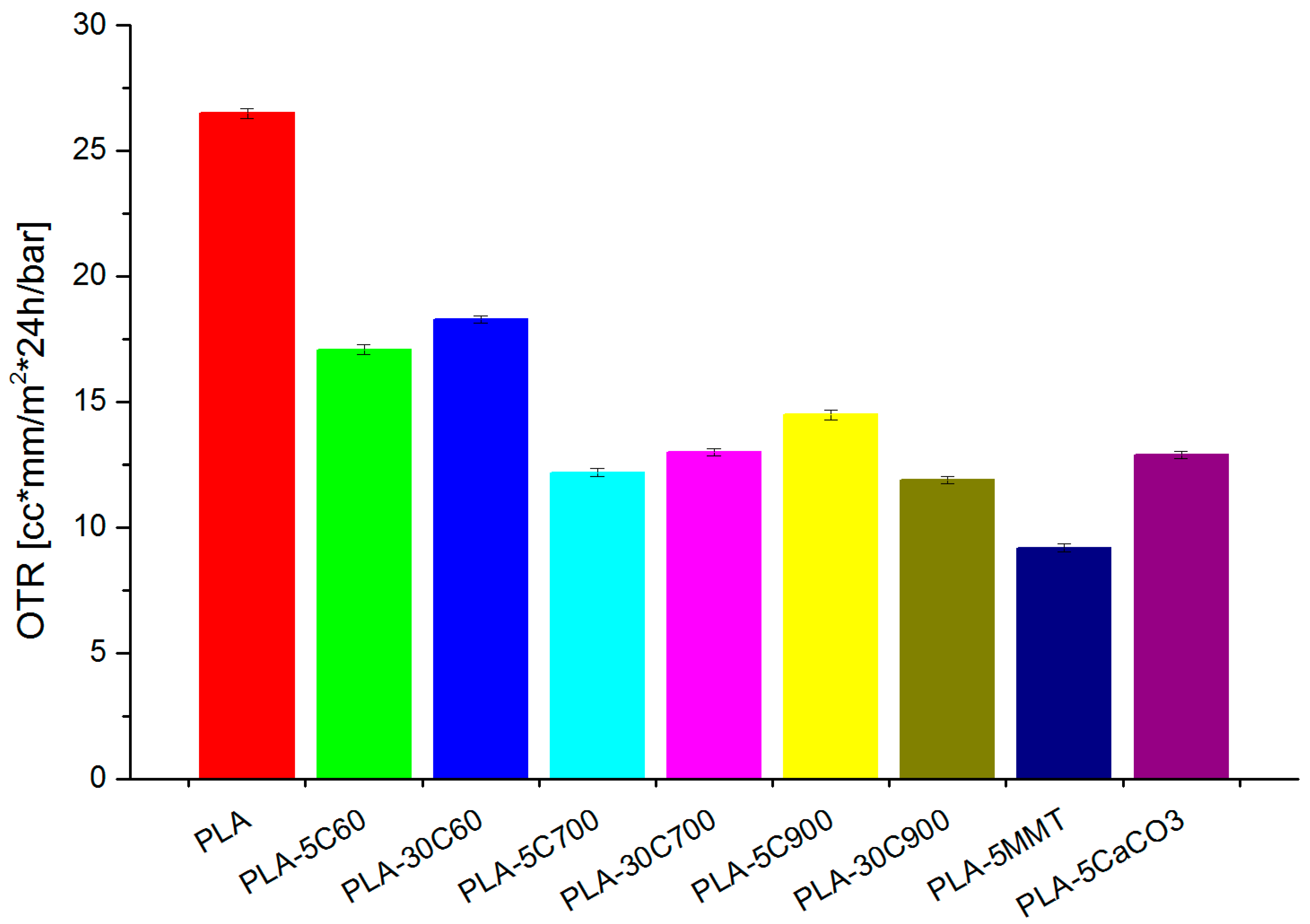
- Enhanced barrier properties, attractive for packaging purposes, were received due to dispersion of montmorillonite nanoparticles in PLA.
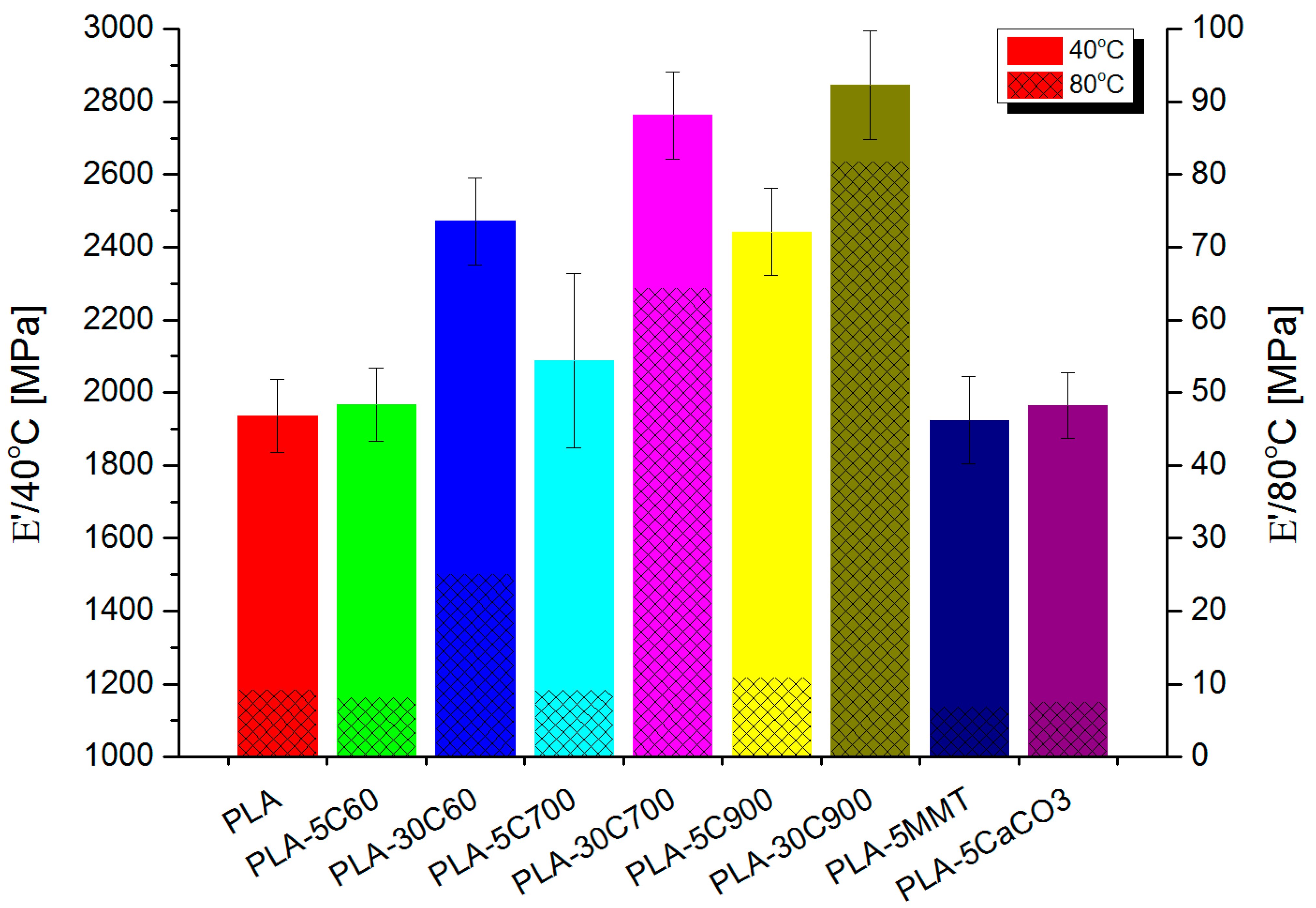
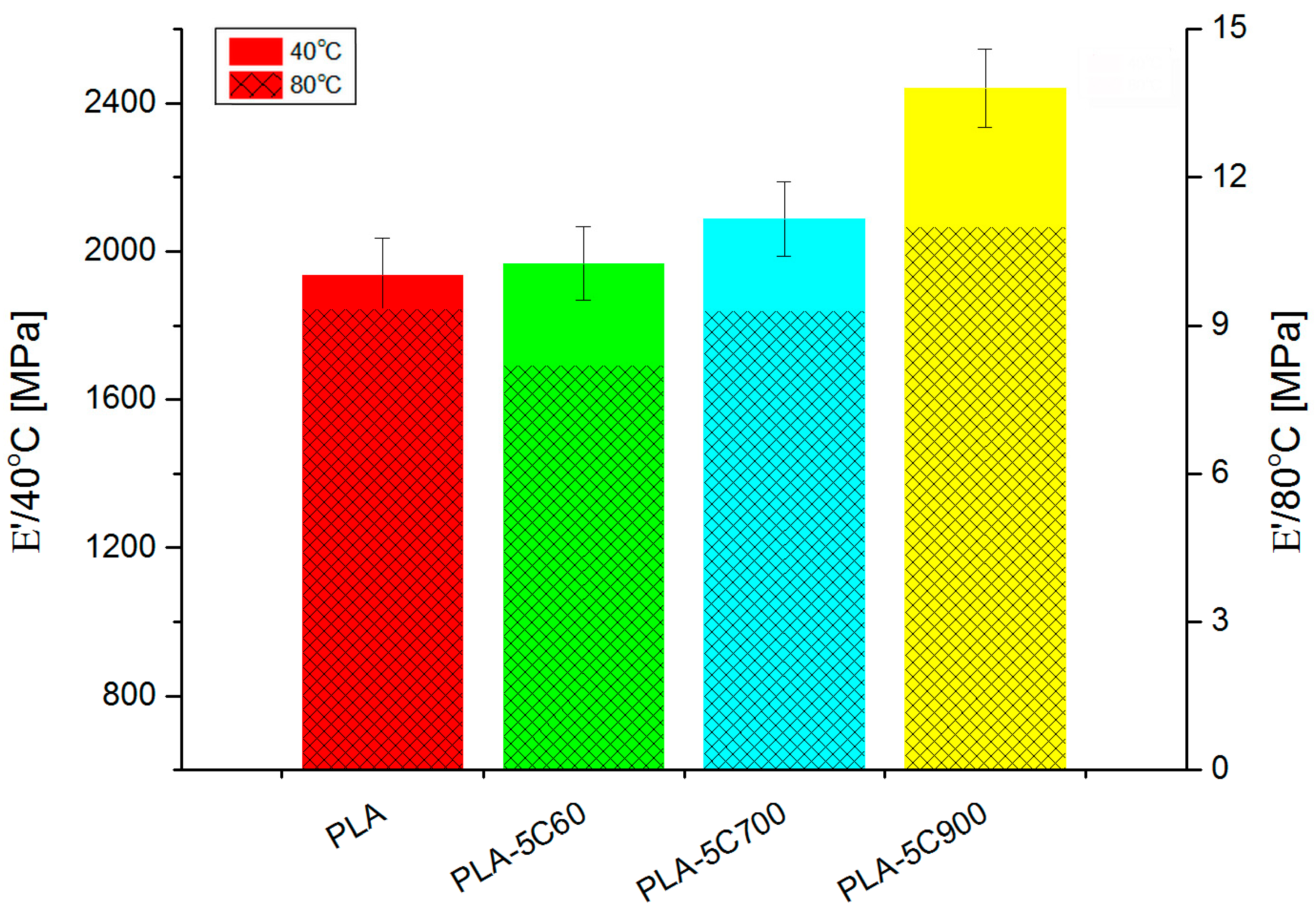
- Fibrous composites (long fibres) reveal signs of filler alignment that was pronounced in thermal and tensile measurements.
Author Contributions
Funding
Data Availability Statement
Conflicts of Interest
Sample Availability
References
- Wróblewska-Krepsztul, J.; Rydzkowski, T.; Borowski, G.; Szczypiński, M.; Klepka, T.; Thakur, V.K. Recent Progress in Biodegradable Polymers and Nanocomposite-Based Packaging Materials for Sustainable Environment. Int. J. Polym. Anal. Charact. 2018, 23, 383–395. [Google Scholar] [CrossRef]
- Platnieks, O.; Barkane, A.; Ijudina, N.; Gaidukova, G.; Thakur, V.K.; Gaidukovs, S. Sustainable Tetra Pak Recycled Cellulose/Poly(Butylene Succinate) Based Woody-like Composites for a Circular Economy. J. Clean. Prod. 2020, 270, 122321. [Google Scholar] [CrossRef]
- Platnieks, O.; Gaidukovs, S.; Neibolts, N.; Barkane, A.; Gaidukova, G.; Thakur, V.K. Poly(Butylene Succinate) and Graphene Nanoplatelet–Based Sustainable Functional Nanocomposite Materials: Structure-Properties Relationship. Mater. Today Chem. 2020, 18, 100351. [Google Scholar] [CrossRef]
- Trache, D.; Thakur, V.K.; Boukherroub, R. Cellulose Nanocrystals/Graphene Hybrids—A Promising New Class of Materials for Advanced Applications. Nanomaterials 2020, 10, 1523. [Google Scholar] [CrossRef]
- Neibolts, N.; Platnieks, O.; Gaidukovs, S.; Barkane, A.; Thakur, V.K.; Filipova, I.; Mihai, G.; Zelca, Z.; Yamaguchi, K.; Enachescu, M. Needle-Free Electrospinning of Nanofibrillated Cellulose and Graphene Nanoplatelets Based Sustainable Poly (Butylene Succinate) Nanofibers. Mater. Today Chem. 2020, 17, 100301. [Google Scholar] [CrossRef]
- Vink, E.T.H.; Rábago, K.R.; Glassner, D.A.; Gruber, P.R. Applications of Life Cycle Assessment to NatureWorksTM Polylactide (PLA) Production. Polym. Degrad. Stab. 2003, 80, 403–419. [Google Scholar] [CrossRef]
- Lunt, J. Large-Scale Production, Properties and Commercial Applications of Polylactic Acid Polymers. Polym. Degrad. Stab. 1998, 59, 145–152. [Google Scholar] [CrossRef]
- Perego, G.; Cella, G.D.; Bastioli, C. Effect of Molecular Weight and Crystallinity on Poly(Lactic Acid) Mechanical Properties. J. Appl. Polym. Sci. 1996, 59, 37–43. [Google Scholar] [CrossRef]
- Doi, Y.; Fukuda, K. (Eds.) Biodegradable Plastics and Polymers, 1st ed.; Elsevier Science: Osaka, Japan, 1994; Volume 12, p. 627. [Google Scholar]
- Gurunathan, T.; Mohanty, S.; Nayak, S.K. A Review of the Recent Developments in Biocomposites Based on Natural Fibres and Their Application Perspectives. Compos. Part Appl. Sci. Manuf. 2015, 77, 1–25. [Google Scholar] [CrossRef]
- Platnieks, O.; Gaidukovs, S.; Barkane, A.; Sereda, A.; Gaidukova, G.; Grase, L.; Thakur, V.K.; Filipova, I.; Fridrihsone, V.; Skute, M.; et al. Bio-Based Poly(Butylene Succinate)/Microcrystalline Cellulose/Nanofibrillated Cellulose-Based Sustainable Polymer Composites: Thermo-Mechanical and Biodegradation Studies. Polymers 2020, 12, 1472. [Google Scholar] [CrossRef]
- Platnieks, O.; Gaidukovs, S.; Barkane, A.; Gaidukova, G.; Grase, L.; Thakur, V.K.; Filipova, I.; Fridrihsone, V.; Skute, M.; Laka, M. Highly Loaded Cellulose/Poly (Butylene Succinate) Sustainable Composites for Woody-Like Advanced Materials Application. Molecules 2020, 25, 121. [Google Scholar] [CrossRef] [PubMed]
- Ates, B.; Koytepe, S.; Ulu, A.; Gurses, C.; Thakur, V.K. Chemistry, Structures, and Advanced Applications of Nanocomposites from Biorenewable Resources. Chem. Rev. 2020, 120, 9304–9362. [Google Scholar] [CrossRef] [PubMed]
- Dubey, S.P.; Thakur, V.K.; Krishnaswamy, S.; Abhyankar, H.A.; Marchante, V.; Brighton, J.L. Progress in Environmental-Friendly Polymer Nanocomposite Material from PLA: Synthesis, Processing and Applications. Vacuum 2017, 146, 655–663. [Google Scholar] [CrossRef]
- Pappu, A.; Pickering, K.L.; Thakur, V.K. Manufacturing and Characterization of Sustainable Hybrid Composites Using Sisal and Hemp Fibres as Reinforcement of Poly (Lactic Acid) via Injection Moulding. Ind. Crops Prod. 2019, 137, 260–269. [Google Scholar] [CrossRef]
- Meinander, K.; Niemi, M.; Hakola, J.S.; Selin, J.-F. Polylactides—Degradable Polymers for Fibres and Films. Macromol. Symp. 1997, 123, 147–153. [Google Scholar] [CrossRef]
- Wróblewska-Krepsztul, J.; Rydzkowski, T.; Michalska-Pożoga, I.; Thakur, V.K. Biopolymers for Biomedical and Pharmaceutical Applications: Recent Advances and Overview of Alginate Electrospinning. Nanomaterials 2019, 9, 404. [Google Scholar] [CrossRef]
- Sinclair, R.G. The Case for Polylactic Acid as a Commodity Packaging Plastic. J. Macromol. Sci. Part A 1996, 33, 585–597. [Google Scholar] [CrossRef]
- De Vlieger, J.J. Green plastics for food packaging. In Novel Food Packaging Techniques; Elsevier: Amsterdam, The Netherlands, 2003; pp. 519–534. ISBN 978-1-85573-675-7. [Google Scholar]
- Alexandre, M.; Dubois, P. Polymer-Layered Silicate Nanocomposites: Preparation, Properties and Uses of a New Class of Materials. Mater. Sci. Eng. R Rep. 2000, 28, 1–63. [Google Scholar] [CrossRef]
- Auras, R.; Lim, L.-T.; Selke, S.E.M.; Tsuji, H. (Eds.) Poly(Lactic Acid): Synthesis, Structures, Properties, Processing, and Applications; John Wiley & Sons, Inc.: Hoboken, NJ, USA, 2010; ISBN 978-0-470-64984-8. [Google Scholar]
- Dorgan, J.R. Rheology of Poly(Lactic Acid). In Poly(Lactic Acid); Auras, R., Lim, L.-T., Selke, S.E.M., Tsuji, H., Eds.; John Wiley & Sons, Inc.: Hoboken, NJ, USA, 2010; pp. 125–139. ISBN 978-0-470-64984-8. [Google Scholar]
- Jin, Z.; Tian, Y.; Wang, J. Chemistry and Thermodynamic Properties of Lactic Acid and Lactide and Solvent Miscibility. In Poly(Lactic Acid); Auras, R., Lim, L.-T., Selke, S.E.M., Tsuji, H., Eds.; John Wiley & Sons, Inc.: Hoboken, NJ, USA, 2010; pp. 19–25. ISBN 978-0-470-64984-8. [Google Scholar]
- Wollerdorfer, M.; Bader, H. Influence of Natural Fibres on the Mechanical Properties of Biodegradable Polymers. Ind. Crops Prod. 1998, 2, 105–112. [Google Scholar] [CrossRef]
- Trache, D.; Tarchoun, A.F.; Derradji, M.; Hamidon, T.S.; Masruchin, N.; Brosse, N.; Hussin, M.H. Nanocellulose: From Fundamentals to Advanced Applications. Front. Chem. 2020, 8, 392. [Google Scholar] [CrossRef]
- Satyanarayana, K.G.; Sukumaran, K.; Mukherjee, P.S.; Pavithran, C.; Pillai, S.G.K. Natural Fibre-Polymer Composites. Cem. Concr. Compos. 1990, 12, 117–136. [Google Scholar] [CrossRef]
- Pickering, K. Properties and Performance of Natural-Fibre Composites, 1st ed.; Woodhead Publishing: Sawston/Cambridge, UK, 2008; ISBN 978-1-84569-267-4. [Google Scholar]
- Singha, A.S.; Thakur, V.K. Fabrication and Characterization of H. Sabdariffa Fiber-Reinforced Green Polymer Composites. Polym.-Plast. Technol. Eng. 2009, 48, 482–487. [Google Scholar] [CrossRef]
- Singha, A.S.; Thakur, V.K. Synthesis and Characterization of Pine Needles Reinforced RF Matrix Based Biocomposites. E-J. Chem. 2008, 5, 1055–1062. [Google Scholar] [CrossRef]
- Singha, A.S.; Thakur, V.K. Physical, Chemical and Mechanical Properties of Hibiscus Sabdariffa Fiber/Polymer Composite. Int. J. Polym. Mater. Polym. Biomater. 2009, 58, 217–228. [Google Scholar] [CrossRef]
- Azizi Samir, M.A.S.; Alloin, F.; Dufresne, A. Review of Recent Research into Cellulosic Whiskers, Their Properties and Their Application in Nanocomposite Field. Biomacromolecules 2005, 6, 612–626. [Google Scholar] [CrossRef]
- Sanchez-Garcia, M.D.; Gimenez, E.; Lagaron, J.M. Morphology and Barrier Properties of Solvent Cast Composites of Thermoplastic Biopolymers and Purified Cellulose Fibers. Carbohydr. Polym. 2008, 71, 235–244. [Google Scholar] [CrossRef]
- Fendler, A.; Villanueva, M.P.; Gimenez, E.; Lagarón, J.M. Characterization of the Barrier Properties of Composites of HDPE and Purified Cellulose Fibers. Cellulose 2007, 14, 427–438. [Google Scholar] [CrossRef]
- Dufresne, A. Cellulose-Based Composites and Nanocomposites. In Monomers, Polymers and Composites from Renewable Resources; Elsevier: Amsterdam, The Netherlands, 2008; pp. 401–418. ISBN 978-0-08-045316-3. [Google Scholar]
- Iturrondobeitia, M.; Okariz, A.; Guraya, T.; Zaldua, A.-M.; Ibarretxe, J. Influence of the Processing Parameters and Composition on the Thermal Stability of PLA/Nanoclay Bio-Nanocomposites. J. Appl. Polym. Sci. 2014, 131. [Google Scholar] [CrossRef]
- Nieddu, E.; Mazzucco, L.; Gentile, P.; Benko, T.; Balbo, V.; Mandrile, R.; Ciardelli, G. Preparation and Biodegradation of Clay Composites of PLA. React. Funct. Polym. 2009, 69, 371–379. [Google Scholar] [CrossRef]
- Pirani, S.; Krishnamachari, P.; Hashaikeh, R. Optimum Loading Level of Nanoclay in PLA Nanocomposites: Impact on the Mechanical Properties and Glass Transition Temperature. J. Thermoplast. Compos. Mater. 2013, 27, 1–18. [Google Scholar] [CrossRef]
- Lewitus, D.; McCarthy, S.; Ophir, A.; Kenig, S. The Effect of Nanoclays on the Properties of PLLA-Modified Polymers Part 1: Mechanical and Thermal Properties. J. Polym. Environ. 2006, 14, 171–177. [Google Scholar] [CrossRef]
- Najafi, N.; Heuzey, M.C.; Carreau, P.J. Polylactide (PLA)-Clay Nanocomposites Prepared by Melt Compounding in the Presence of a Chain Extender. Compos. Sci. Technol. 2012, 72, 608–615. [Google Scholar] [CrossRef]
- Liu, D.Y.; Yuan, X.W.; Bhattacharyya, D.; Easteal, A.J. Characterisation of Solution Cast Cellulose Nanofibre—Reinforced Poly(Lactic Acid). Express Polym. Lett. 2010, 4, 26–31. [Google Scholar] [CrossRef]
- Thakur, V.K.; Singha, A.S.; Kaur, I.; Nagarajarao, R.P.; Liping, Y. Silane Functionalization of Saccaharum Cilliare Fibers: Thermal, Morphological, and Physicochemical Study. Int. J. Polym. Anal. Charact. 2010, 15, 397–414. [Google Scholar] [CrossRef]
- Usmani, Z.; Sharma, M.; Awasthi, A.K.; Sivakumar, N.; Lukk, T.; Pecoraro, L.; Thakur, V.K.; Roberts, D.; Newbold, J.; Gupta, V.K. Bioprocessing of Waste Biomass for Sustainable Product Development and Minimizing Environmental Impact. Bioresour. Technol. 2020, 124548. [Google Scholar] [CrossRef]
- Pothan, L.A.; Oommen, Z.; Thomas, S. Dynamic Mechanical Analysis of Banana Fiber Reinforced Polyester Composites. Compos. Sci. Technol. 2003, 63, 283–293. [Google Scholar] [CrossRef]
- Singha, A.S.; Thakur, V.K. Grewia Optiva Fiber Reinforced Novel, Low Cost Polymer Composites. E-J. Chem. 2009, 6, 71–76. [Google Scholar] [CrossRef]
- Singha, A.S.; Thakur, V.K. Mechanical, Morphological and Thermal Properties of Pine Needle-Reinforced Polymer Composites. Int. J. Polym. Mater. Polym. Biomater. 2008, 58, 21–31. [Google Scholar] [CrossRef]
- Reihmane, S.; Bledzki, A.; Gassan, J. Properties and Modification Methods for Vegetable Fibers for Natural Fiber Composites. J. Appl. Polym. Sci. 1996, 59, 1329–1336. [Google Scholar]
- Rowell, R.M. (Ed.) Handbook of Wood Chemistry and Wood Composites, 2nd ed.; CRC Press: Boca Raton, FL, USA, 2012; Volume 1, ISBN 978-0-429-10909-6. [Google Scholar]
- Caraschi, J.C.; Leão, A.L. Woodflour as Reinforcement of Polypropylene. Mater. Res. 2002, 5, 405–409. [Google Scholar] [CrossRef]
- Herrera-Franco, P.J.; Valadez-González, A. Mechanical Properties of Continuous Natural Fibre-Reinforced Polymer Composites. Compos. Part Appl. Sci. Manuf. 2004, 35, 339–345. [Google Scholar] [CrossRef]
- Wambua, P.; Ivens, J.; Verpoest, I. Natural Fibres: Can They Replace Glass in Fibre Reinforced Plastics? Compos. Sci. Technol. 2003, 63, 1259–1264. [Google Scholar] [CrossRef]
- Heijenrath, R.; Peijs, T. Natural-Fibre-Mat-Reinforced Thermoplastic Composites Based on Flax Fibres and Polypropylene. Adv. Compos. Lett. 1996, 5, 096369359600500. [Google Scholar] [CrossRef]
- Singha, A.S.; Thakur, V.K. Synthesis, Characterisation and Analysis of Hibiscus Sabdariffa Fibre Reinforced Polymer Matrix Based Composites. Polym. Polym. Compos. 2009, 17, 189–194. [Google Scholar] [CrossRef]
- Singha, A.S.; Thakur, V.K. Fabrication of Hibiscus Sabdariffa Fibre Reinforced Polymer Composites. Iran. Polym. J. 2008, 17, 541–553. [Google Scholar]
- Singha, A.S.; Shama, A.; Thakur, V.K. X-Ray Diffraction, Morphological, and Thermal Studies on Methylmethacrylate Graft Copolymerized Saccharum Ciliare Fiber. Int. J. Polym. Anal. Charact. 2008, 13, 447–462. [Google Scholar] [CrossRef]
- Gigante, V.; Aliotta, L.; Phuong, V.T.; Coltelli, M.B.; Cinelli, P.; Lazzeri, A. Effects of Waviness on Fiber-Length Distribution and Interfacial Shear Strength of Natural Fibers Reinforced Composites. Compos. Sci. Technol. 2017, 152, 129–138. [Google Scholar] [CrossRef]
- Aliotta, L.; Cinelli, P.; Coltelli, M.B.; Lazzeri, A. Rigid Filler Toughening in PLA-Calcium Carbonate Composites: Effect of Particle Surface Treatment and Matrix Plasticization. Eur. Polym. J. 2019, 113, 78–88. [Google Scholar] [CrossRef]
- Aliotta, L.; Gigante, V.; Coltelli, M.B.; Cinelli, P.; Lazzeri, A. Evaluation of Mechanical and Interfacial Properties of Bio-Composites Based on Poly(Lactic Acid) with Natural Cellulose Fibers. Int. J. Mol. Sci. 2019, 20, 960. [Google Scholar] [CrossRef]
- Piekarska, K.; Piorkowska, E.; Bojda, J. The Influence of Matrix Crystallinity, Filler Grain Size and Modification on Properties of PLA/Calcium Carbonate Composites. Polym. Test. 2017, 62, 203–209. [Google Scholar] [CrossRef]
- Tjong, S.C. Structural and Mechanical Properties of Polymer Nanocomposites. Mater. Sci. Eng. R Rep. 2006, 53, 73–197. [Google Scholar] [CrossRef]
- Asadi, Z.; Javadi, A.; Mohammadzadeh, F.; Alavi, K. Investigation on the Role of Nanoclay and Nano Calcium Carbonate on Morphology, Rheology, Crystallinity and Mechanical Properties of Binary and Ternary Nanocomposites Based on PLA. Int. J. Polym. Anal. Charact. 2020, 1–16. [Google Scholar] [CrossRef]
- Pacheco-Torgal, F.; Rasmussen, E.; Granqvist, C.G.; Ivanov, V.; Kaklauskas, A.; Makonin, S. (Eds.) Start-Up Creation: The Smart Eco-Efficient Built Environment, 1st ed.; Elsevier: Amsterdam, The Netherlands, 2016; ISBN 978-0-08-100546-0. [Google Scholar]


| Parameter | Value | Unit |
|---|---|---|
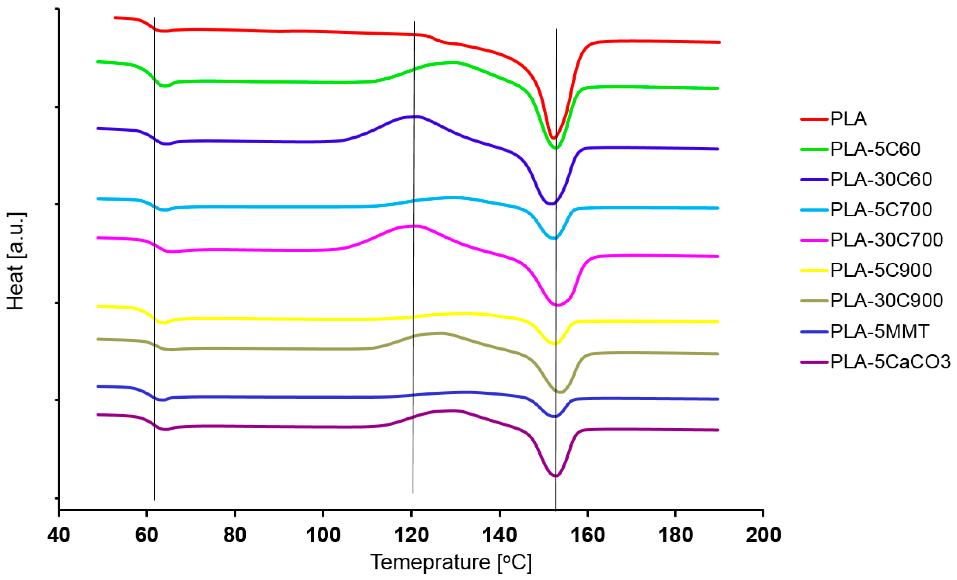
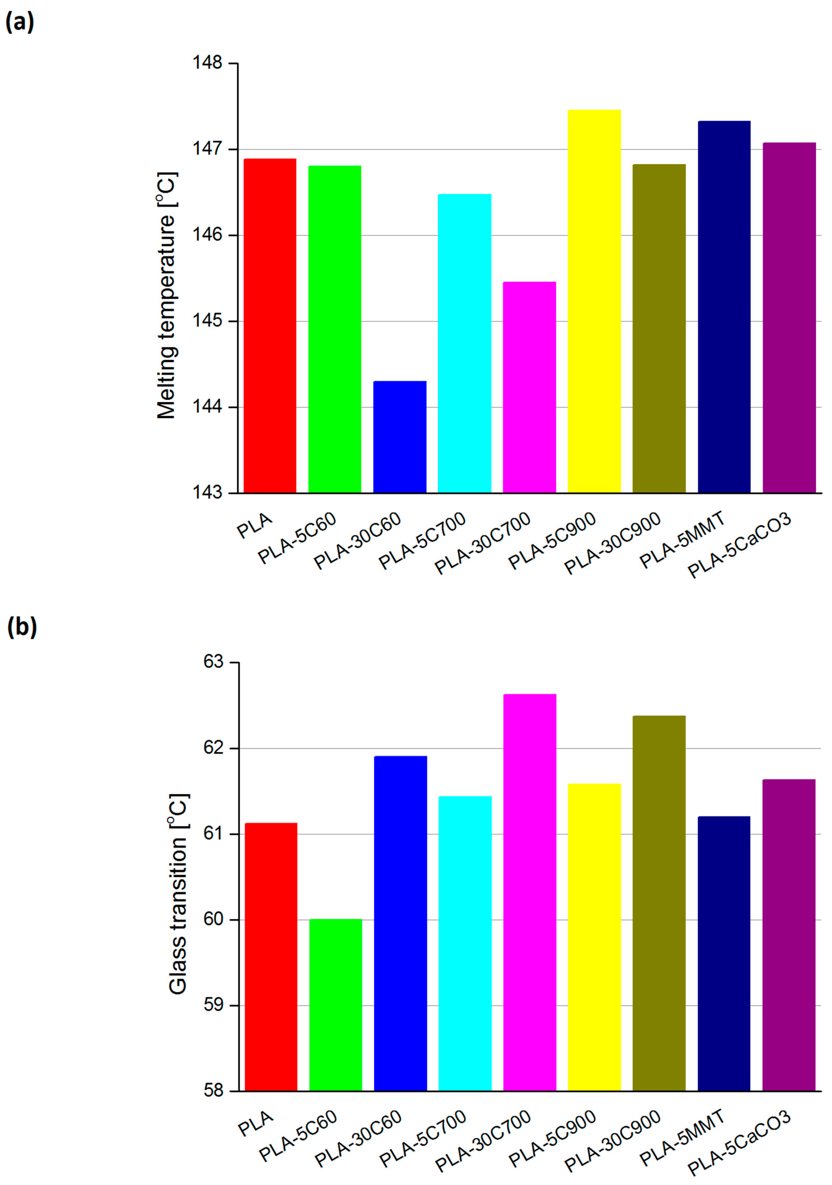
| Melting temperature | 150–165 | °C |
| Glass transition temperature | 55–65 | °C |
| MFR (2.16 kg, 210 °C, std die) | 10–25 | g/10 min |
| Clarity | Transparent | - |
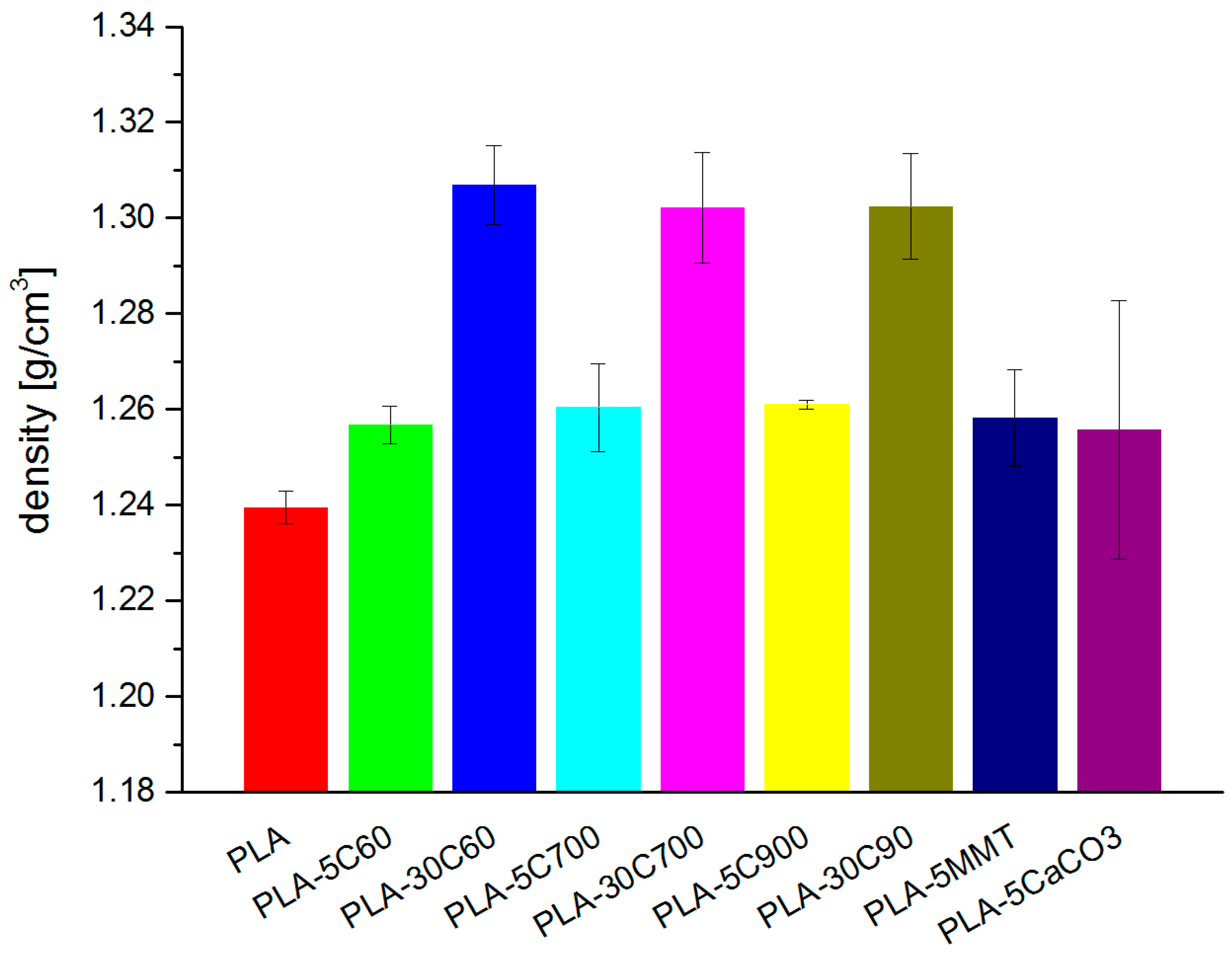
| Sample | Theoretical | Measured | Δ (%) |
|---|---|---|---|
| PLA-5 °C | 1.262 | 1.26 | 0.4 |
| PLA-30 °C | 1.384 | 1.31 | 5.9 |
| PLA-5MMT | 1.264 | 1.26 | 0.5 |
| PLA-5CaCO3 | 1.245 | 1.26 | 0.9 |
| E’ | 40 °C | 80 °C | C Coeff |
|---|---|---|---|
| PLA | 1936 | 9.3 | - |
| PLA-5C60 | 1968 | 8.2 | 1.2 |
| PLA-30C60 | 2472 | 25 | 0.5 |
| PLA-5C700 | 2088 | 9.3 | 1.1 |
| PLA-30C700 | 2763 | 64 | 0.2 |
| PLA-5C900 | 2442 | 11 | 1.1 |
| PLA-30C900 | 2846 | 82 | 0.2 |
| PLA-5MMT | 1924 | 6.9 | 1.3 |
| PLA-5CaCO3 | 1965 | 7.6 | 1.2 |
Publisher’s Note: MDPI stays neutral with regard to jurisdictional claims in published maps and institutional affiliations. |
© 2020 by the authors. Licensee MDPI, Basel, Switzerland. This article is an open access article distributed under the terms and conditions of the Creative Commons Attribution (CC BY) license (http://creativecommons.org/licenses/by/4.0/).
Share and Cite
Leluk, K.; Frąckowiak, S.; Ludwiczak, J.; Rydzkowski, T.; Thakur, V.K. The Impact of Filler Geometry on Polylactic Acid-Based Sustainable Polymer Composites. Molecules 2021, 26, 149. https://doi.org/10.3390/molecules26010149
Leluk K, Frąckowiak S, Ludwiczak J, Rydzkowski T, Thakur VK. The Impact of Filler Geometry on Polylactic Acid-Based Sustainable Polymer Composites. Molecules. 2021; 26(1):149. https://doi.org/10.3390/molecules26010149
Chicago/Turabian StyleLeluk, Karol, Stanisław Frąckowiak, Joanna Ludwiczak, Tomasz Rydzkowski, and Vijay Kumar Thakur. 2021. "The Impact of Filler Geometry on Polylactic Acid-Based Sustainable Polymer Composites" Molecules 26, no. 1: 149. https://doi.org/10.3390/molecules26010149
APA StyleLeluk, K., Frąckowiak, S., Ludwiczak, J., Rydzkowski, T., & Thakur, V. K. (2021). The Impact of Filler Geometry on Polylactic Acid-Based Sustainable Polymer Composites. Molecules, 26(1), 149. https://doi.org/10.3390/molecules26010149