Dichotomic Decision Optimization for the Design of HVDC Superconducting Links


Abstract
1. Introduction
- Road vehicle traction system [9]: three options are common: front-, rear-, or all-wheel drive. Depending on the chosen use, the weather conditions (snow), the required power, etc., the optimum decision is going to change, affecting the remaining design parameters of the car.
- Airplane engines location [10]: several options are available, for instance, front wings or rear wings. Each of them gives different possibilities in terms of manageability and puts the airplane under different mechanical stresses: compression (rear wings) and traction (front wings).
- Thermal cycle cold sink in power plants [11]: a dry cooling system is cheaper but decreases the cycle efficiency when compared to a wet cooling system, which usually conditions the location of the power plant.
- Windmill morphology [12]: the three-bladed windmill is not the most efficient, but is commonly used at present, due to the balance between cost, reliability, and efficiency.
2. Background: Technologies for Bulk Power Transmission
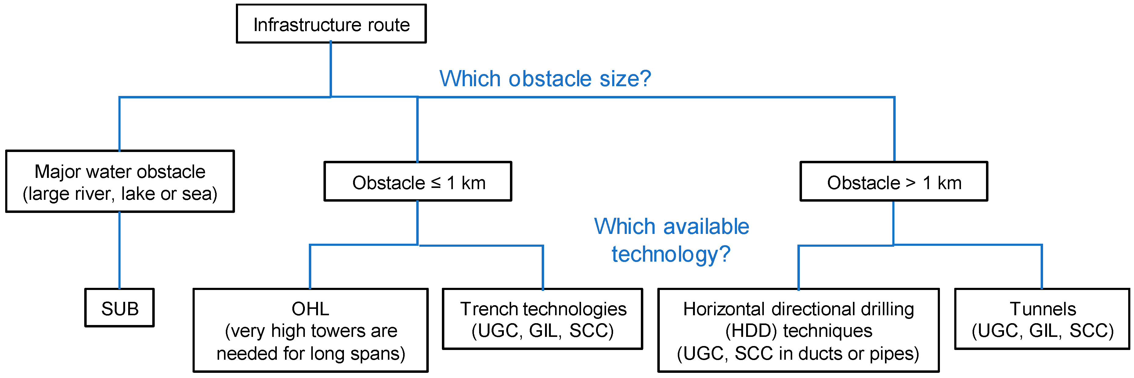
2.1. Selection of Link Technology
2.2. Additional Selection Criteria
 for high difficulty), depending on whether advantages or disadvantages are described. Furthermore, these various aspects are addressed in detail below, providing a state-of-the-art overview that highlights the complexity of the decision-making process.
2.2.1. Visual Impact
2.2.2. Infrastructure Footprint and Right-of-Way
2.2.3. Sensitivity to Climatic Hazards
2.2.4. Sensitivity to Ambient Temperature
2.2.5. Sensitivity to Rocky Environment
2.2.6. Ease of Making Joints
2.2.7. Repairability
2.2.8. Resilience and Contingency
2.2.9. Monitoring and Maintenance
2.2.10. Generated Electromagnetic Fields
2.2.11. General Considerations
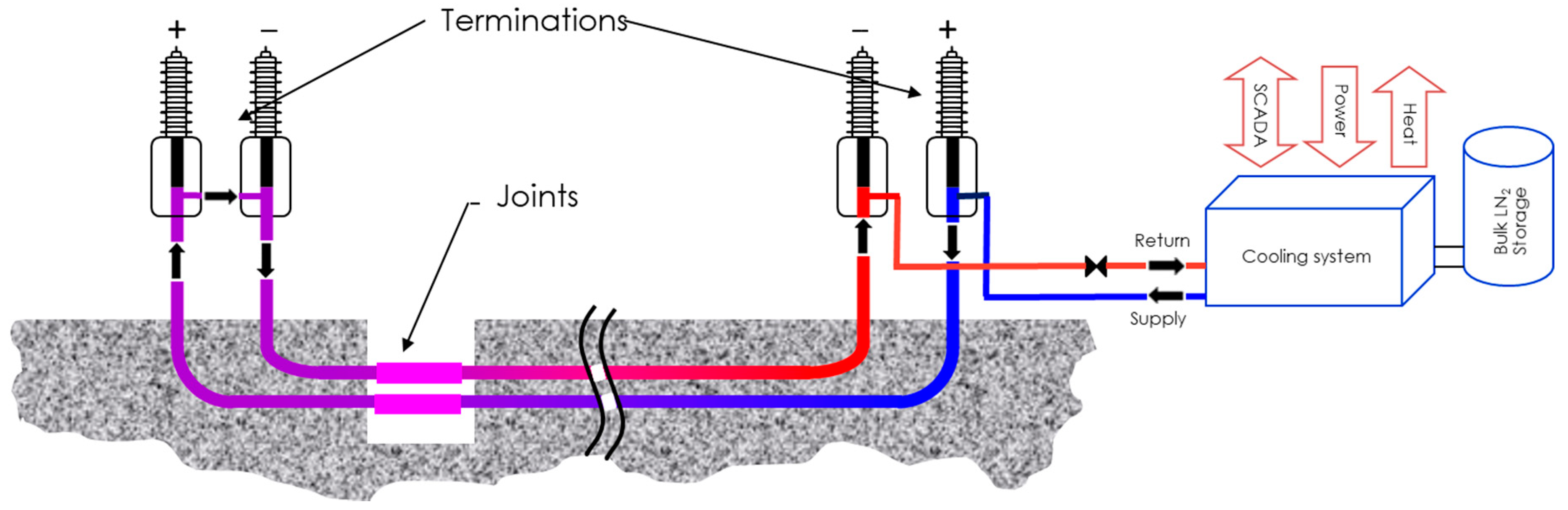
2.3. Main Components of a Superconducting Cable System
- ○
- Superconductor;
- ○
- Cryostat (cryogenic envelope), housing the cooling fluid needed to maintain the superconductor temperature;
- ○
- High-voltage electrical insulation;
- ○
- Cryogenic terminations and joints;
- ○
- Adequate cooling devices connected to associated power and fluid supplies for the auxiliary equipment (chiller, pumps, etc.).
3. Dichotomic Decision Optimization for an HVDC Superconducting Link
3.1. Superconducting Materials and Cooling Fluids
3.1.1. Superconductor Selection
3.1.2. Fluid Selection for the MgB2 Superconducting Cable
3.2. Design of the Cryogenic Envelope
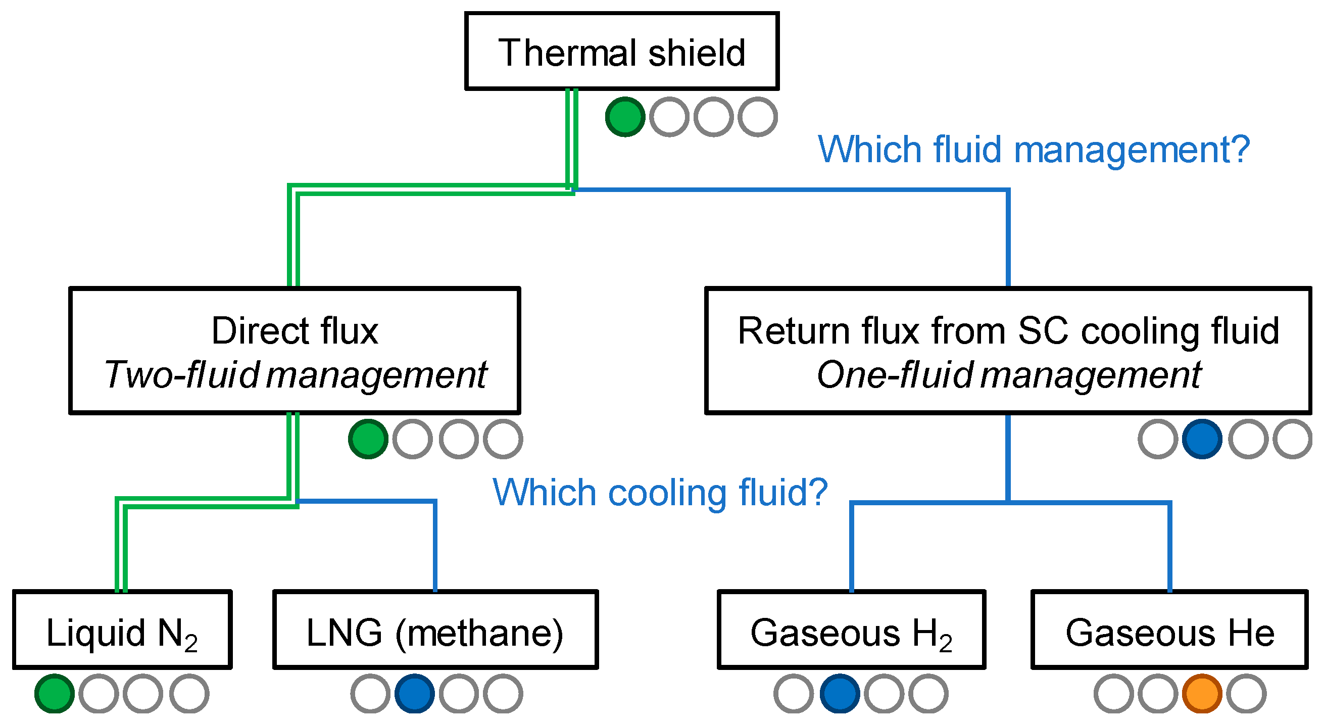
3.3. Fluid Selection for the Thermal Shield
3.4. High-Voltage Insulation
3.5. Protection of the Cable System
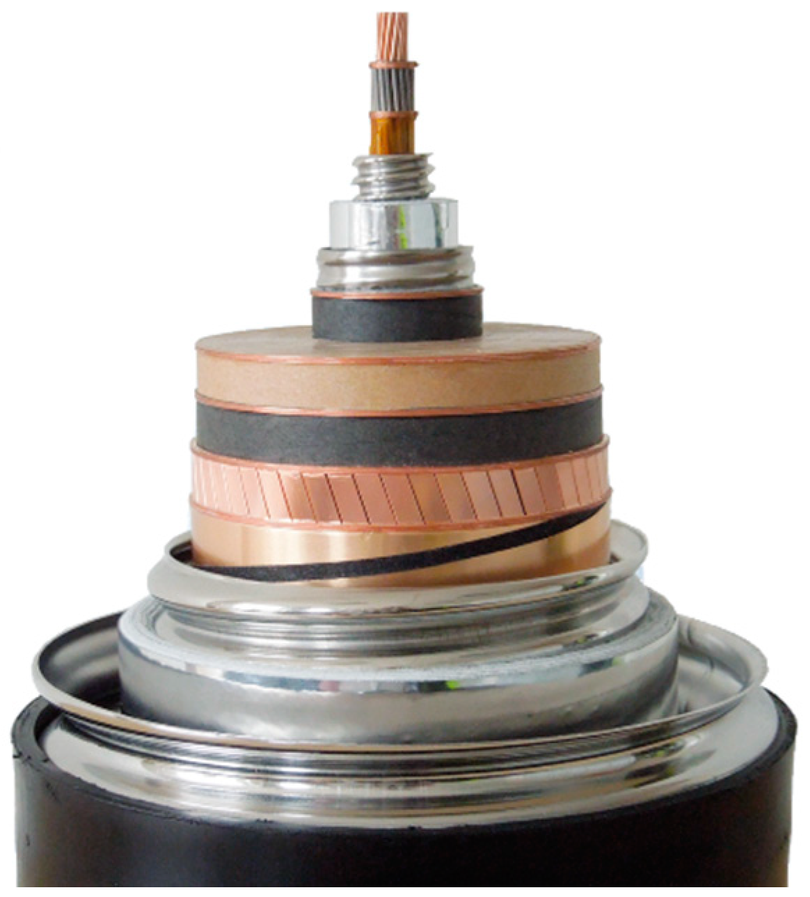
- The “fault tolerant” conductor design withstands the quench, with an over-current during the fault but no damage to the conductor. This is due to the copper core of the cable (see Figure 4), which acts as a low-resistance electrical shunt protecting the superconducting wires and transporting the current in excess of the superconducting critical current. The cable must be disconnected from the grid and can be energized again after the recovery of the operating temperature.
- The “fault transparent” conductor design is enabled by the high current and good thermal stability of the MgB2 superconductor, which come at an affordable cost. In such a design, a conductor consisting of multiple high-current MgB2 strands can withstand the fault current without a quench.
4. Conclusions and Future Work
Author Contributions
Funding
Acknowledgments
Conflicts of Interest
References
- Grant, P.M. Fantastic five—Top five applications of superconductivity. Phys. World 2011, 4, 23–25. [Google Scholar]
- Müller, K.A.; Bednorz, J.G. The discovery of a class of high-temperature superconductors. Science 1987, 237, 1133–1139. [Google Scholar] [CrossRef] [PubMed]
- Nishijima, S.; Eckroad, S.; Marian, A.; Choi, K.; Kim, W.S.; Terai, M.; Deng, Z.; Zheng, J.; Wang, J.; Umemoto, K.; et al. Superconductivity and the environment: A Roadmap. Supercond. Sci. Technol. 2013, 26, 113001. [Google Scholar] [CrossRef]
- Thomas, H.; Marian, A.; Chervyakov, A.; Stückrad, S.; Salmieri, D.; Rubbia, C. Superconducting transmission lines—Sustainable electric energy transfer with higher public acceptance? Renew. Sustain. Energy Rev. 2016, 55, 59–72. [Google Scholar] [CrossRef]
- EPRI. Superconducting Power Equipment: Technology Watch 2012; EPRI Report No. 1024190; Electric Power Research Institute: Palo Alto, CA, USA, 2012. [Google Scholar]
- Stemmle, M.; Merschel, F.; Noe, M.; Hobl, A. AmpaCity project—Worldwide first superconducting cable and fault current limiter installation in a German city center. In Proceedings of the 22nd International Conference and Exhibition on Electricity Distribution (CIRED 2013), Stockholm, Sweden, 10–13 June 2013; pp. 1–4. [Google Scholar]
- Nagamatsu, J.; Nakagawa, N.; Muranaka, T.; Zenitani, Y.; Akimitsu, J. Superconductivity at 39 K in magnesium diboride. Nature 2001, 410, 63–64. [Google Scholar] [CrossRef] [PubMed]
- Braccini, V.; Nardelli, D.; Penco, R.; Grasso, G. Development of ex situ processed MgB2 wires and their applications to magnets. Physica C Supercond. 2007, 456, 209–217. [Google Scholar] [CrossRef]
- Lucas, G.G. Road Vehicle Performance: Methods of Measurement and Calculation; Taylor & Francis: Milton Park, UK, 1986. [Google Scholar]
- Hull, D.G. Fundamentals of Airplane Flight Mechanics; Springer: Berlin/Heidelberg, Germany, 2007. [Google Scholar]
- Kröger, D.G. Air-Cooled Heat Exchangers and Cooling Towers; Pennwell Corp.: Tulsa, OK, USA, 2004. [Google Scholar]
- Schubel, P.J.; Crossley, R.J. Wind Turbine Blade Design. Energies 2012, 5, 3425–3449. [Google Scholar] [CrossRef]
- Ballarino, A.; Bruzek, C.E.; Dittmar, N.; Giannelli, S.; Goldacker, W.; Grasso, G.; Grilli, F.; Haberstroh, C.; Holé, S.; Lesur, F.; et al. The BEST PATHS project on MgB2 superconducting cables for very high power transmission. IEEE Trans. Appl. Supercond. 2016, 26, 5401705. [Google Scholar] [CrossRef]
- Marian, A.; Holé, S.; Lallouet, N.; Marzahn, E.; Bruzek, C.E. Demonstration tests of a 320-kV-class DC superconducting cable for transmission of high powers. IEEE Electr. Insul. Mag. 2020, 36, 30–40. [Google Scholar] [CrossRef]
- Marian, A.; Bruzek, C.E. Advancing Superconducting Links for Very High Power Transmission. Available online: https://doi.org/10.2312/iass.2018.017 (accessed on 14 December 2020).
- Zhong, J.; Qi, Q.; He, H.; He, H.; Ding, T.; He, J. Study on characteristics of slow-front overvoltage of ±1100 kV UHVDC transmission lines. J. Eng. 2019, 2019, 1726–1729. [Google Scholar] [CrossRef]
- Skog, J.E.; van Asten, H.; Worzyk, T.; Andersrød, T. NorNed—World’s Longest Power Cable. Available online: https://library.e.abb.com/public/22d1dc6a2e72fa27c1257dea00357f41/NorNed%20HVDC%20link%20-%20Worlds%20longest%20power%20cable.pdf (accessed on 14 December 2020).
- Mattsson, I.; Railing, B.D.; Williams, B.; Moreau, G.; Clarke, C.D.; Ericsson, A.; Miller, J.J. The Longest Underground HVDC Cable in the World. Available online: https://library.e.abb.com/public/bc4bec2a99068301c1256fda004c8cca/B4-103.pdf (accessed on 14 December 2020).
- Magier, T.; Tenzer, M.; Koch, H. Direct Current Gas-Insulated Transmission Lines. IEEE Trans. Power Delivery 2018, 33, 440–446. [Google Scholar] [CrossRef]
- McRobbie, D. Guidelines for limiting exposure to time-varying electric and magnetic fields (1 Hz–100 kHz). Health Phys. 2010, 99, 818–836. [Google Scholar]
- ICNIRP. Guidelines on limits of exposure to static magnetic fields. Health Phys. 2009, 96, 504–514. [Google Scholar] [CrossRef]
- Cigré Working Group B1.36, Life Cycle Assessment of Underground Cables, Cigré Technical Brochure 689. 2017. Available online: https://e-cigre.org/publication/689-life-cycle-assessment-of-underground-cables (accessed on 14 December 2020).
- Morandi, A.; Marzinotto, M.; Mazzanti, G. Feasibility of high voltage DC superconducting cables with extruded warm dielectric. In Proceedings of the 2014 IEEE Conference on Electrical Insulation and Dielectric Phenomena (CEIDP), Des Moines, IA, USA, 19–22 October 2014; pp. 796–799. [Google Scholar]
- Marian, A.; Holé, S.; Lesur, F.; Tropeano, M.; Bruzek, C.E. Validation of the superconducting and insulating components of a high-power HVDC cable. IEEE Electr. Insul. Mag. 2018, 34, 26–36. [Google Scholar] [CrossRef]
- Kobayashi, S. Development and Manufacture of Bi-2223 Wires. In Research, Fabrication and Applications of BI-2223 HTS Wires; Sato, K., Ed.; World Scientific Publishing Co. Pte. Ltd.: Singapore, 2016; pp. 137–150. [Google Scholar]
- Bruzek, C.E.; Allais, A.; Dickson, D.; Lallouet, N.; Allweins, K.; Marzahn, E. Superconducting DC cables to improve the efficiency of electricity transmission and distribution networks: An overview. In Eco-Friendly Innovations in Electricity Transmissions and Distribution Networks; Woodhead Publishing Series in Energy; Bessède, J.L., Ed.; Elsevier: Amsterdam, The Netherlands, 2016; Volume 72, pp. 135–167. [Google Scholar] [CrossRef]
- Claudet, S.; Gayet, P.; Lebrun, P.; Tavian, L.; Wagner, U. Economics of Large Helium Cryogenic Systems: Experience from Recent Projects at CERN. In Advances in Cryogenic Engineering; Shu, Q.-S., Ed.; Springer: Boston, MA, USA, 2000; pp. 1301–1308. [Google Scholar]
- Klöppel, S.; Marian, A.; Haberstroh, C.; Bruzek, C.E. Thermo-hydraulic and economic aspects of long-length high-power MgB2 superconducting cables. Cryogenics 2021, 113, 103211. [Google Scholar] [CrossRef]
- Linstrom, P.J.; Mallard, W.G. (Eds.) NIST Chemistry WebBook, NIST Standard Reference Database Number 69, National Institute of Standards and Technology, Gaithersburg, MD. Available online: https://webbook.nist.gov/chemistry/ (accessed on 14 December 2020).
- Cigré Working Group B1.32 Convened by B. Sanden, Recommendations for Testing DC Extruded Cable Systems for Power Transmission at a Rated Voltage up to 500 kV, Cigré Technical Brochure 496. 2012. Available online: https://e-cigre.org/publication/496-recommendations-for-testing-dc-extruded-cable-systems-for-power-transmission-at-a-rated-voltage-up-to-500-kv-this-tb-replaces-tb-219 (accessed on 14 December 2020).
- Goshima, H.; Hayakawa, N.; Hikita, M.; Okubo, H.; Uchida, K. Weibull Statistical Analysis of Area and Volume Effects on the Breakdown Strength in Liquid Nitrogen. IEEE Trans. Dielectr. Electr. Insul. 1995, 2, 385–393. [Google Scholar] [CrossRef]
- Bruzek, C.E.; Ballarino, A.; Escamez, G.; Giannelli, S.; Grilli, F.; Lesur, F.; Marian, A.; Tropeano, M. Cable conductor design for the high-power MgB2 DC superconducting cable project of BEST PATHS. IEEE Trans. Appl. Supercond. 2017, 27, 4801405. [Google Scholar] [CrossRef]


| Criteria | OHL | SUB | UGC | GIL | SCC | Item |
|---|---|---|---|---|---|---|
| Visual impact | | | | | | 2.2.1 |
| Infrastructure footprint and right-of-way | | | | | | 2.2.2 |
| Sensitivity to climatic hazards | | | | | | 2.2.3 |
| Sensitivity to ambient temperature | | | | | | 2.2.4 |
| Sensitivity to rocky environment | | | | | | 2.2.5 |
| Ease of making joints | ★★ ★★ | ★★ | ★★ ★ | ★★ | ★ | 2.2.6 |
| Repairability | ★★ ★★ | 0 | ★★ | ★★ | ★ | 2.2.7 |
| Resilience and contingency | ★★ ★★ | ★ | ★★ | ★★ | ★ | 2.2.8 |
| Monitoring and maintenance | ★ | ★★ ★★ | ★★ ★★ | ★★ | ★★ | 2.2.9 |
| Generated electromagnetic fields (EMF) | ★ | ★★ ★ | ★★ | ★★ ★★ | ★★ ★★ | 2.2.10 |
| Established grid technology | ★★ ★★ | ★★ ★ | ★★ ★ | ★★ | ★ |
| Shape | Dimensions | Performance of Commercial Tapes and Wires | ||||
|---|---|---|---|---|---|---|
| Bi2223 | Laminated PIT * tapes | Width 4.5 mm | Thickness 0.3–0.5 mm | Ic @70 K, 0.5 T 350–400 A.cm−1 | Length < 1500 m | 80–120 €/kA/m |
| YBCO | Laminated thin film coated tapes | Width 4–12 mm | Ic @70 K, 0.5 T 500–800 A.cm−1 | Length < 500 m | ||
| MgB2 | Cylindrical PIT * wires | Ø 0.8–1.5 mm | Ic @20 K, 1T 400 A/mm2 | Length < 3000 m | 3–5 €/kA/m | |
| Liquid N2 | He * | Liquid H2 | Liquid Ne | |
|---|---|---|---|---|
| Abundant and safe | Not rare and safe | Abundant but flammable | Very rare and safe | |
| T solidification (K) | 65 | N/A | 15 | 24.6 |
| T boiling (K) at 3 bar | 87 | 5 | 24 | 31 |
| Cp (J/kg.K) (P, T) | 2000(70K) | 5300(20K) | 9400(20K) | 1800(27K) |
| ρ (kg/m3) | 830(70K) | 5.7(3bar,20K)–9.8(20bar,20K) | 72(20K) | 1212 |
| Viscosity (µPa.s) | 225(70K) | 4(20K) | 15(20K) | 120(27K) |
| No Thermal Shield | With Thermal Shield | ||
|---|---|---|---|
| SCC at 15 K | Shield at 60 K SCC at 15 K | Shield at 100 K SCC at 15 K | |
| Heat inleak at the cold wall (W/m2) | 7.3 | Shield 4.5 Cable 0.7 | Shield 4.5 Cable 1.3 |
| Electrical power to maintain the shield temperature (Din = 120 mm) (Welec/m) | N/A | 22 | 12 |
| Electrical power to maintain the SCC at 15 K (Din = 40 mm) (Welec/m) | 57 | 5 | 10 |
| Total electrical power (Welec/m) | 57 | 27 | 22 |
| Direct Flux | Return Flux | |||
|---|---|---|---|---|
| Liquid N2 | LNG | Gaseous He | Gaseous H2 | |
| Abundant and safe | Abundant but flammable | Common and safe | Abundant but flammable | |
| T solidification (K) | 65 | 91 | N/A | N/A |
| T boiling (K) at 3 bar | 87 | 120 | N/A | N/A |
| Cp (J/kg·K)(T) | 2030(76K) | 3400(105K) | 5200(60K) | 10,700 (60K) |
| ρ (kg/m3) | 812(76K) | 430(105K) | 2.4(3bar) | 1.25(3bar) |
Publisher’s Note: MDPI stays neutral with regard to jurisdictional claims in published maps and institutional affiliations. |
© 2020 by the authors. Licensee MDPI, Basel, Switzerland. This article is an open access article distributed under the terms and conditions of the Creative Commons Attribution (CC BY) license (http://creativecommons.org/licenses/by/4.0/).
Share and Cite
Muñoz-Antón, J.; Marian, A.; Lesur, F.; Bruzek, C.-E. Dichotomic Decision Optimization for the Design of HVDC Superconducting Links. Entropy 2020, 22, 1413. https://doi.org/10.3390/e22121413
Muñoz-Antón J, Marian A, Lesur F, Bruzek C-E. Dichotomic Decision Optimization for the Design of HVDC Superconducting Links. Entropy. 2020; 22(12):1413. https://doi.org/10.3390/e22121413
Chicago/Turabian StyleMuñoz-Antón, Javier, Adela Marian, Frédéric Lesur, and Christian-Eric Bruzek. 2020. "Dichotomic Decision Optimization for the Design of HVDC Superconducting Links" Entropy 22, no. 12: 1413. https://doi.org/10.3390/e22121413
APA StyleMuñoz-Antón, J., Marian, A., Lesur, F., & Bruzek, C.-E. (2020). Dichotomic Decision Optimization for the Design of HVDC Superconducting Links. Entropy, 22(12), 1413. https://doi.org/10.3390/e22121413