Abstract
Continuous-wave magnetrons continue to offer the highest efficiency, lowest cost per watt, and greatest compactness among high-power microwave sources, making them attractive for industrial, scientific, and defense applications. Emerging missions, particularly space solar power systems, industrial microwave heating, and accelerators, demand significantly enhanced performance metrics, including high DC-to-RF efficiency, thermal stability, ultra-low phase noise, and precise phase controllability for coherent operation. To satisfy the critical requirement for high power, low-cost microwave sources with high spectral purity, extensive research has focused on injection-locking techniques, external phase/frequency modulation methods, and large-scale coherent power combining. This paper reviews the fundamental characteristics of CW magnetrons, recent advances in injection-locked magnetron transmitters, power-combining systems employing multiple injection-locked magnetrons, magnetron-based phased-array systems, and emerging applications. Finally, the challenges and promising development directions for next-generation CW magnetrons are discussed.
1. Introduction
In commercial and industrial applications, particularly in microwave heating, continuous-wave (CW) magnetrons continue to outperform solid-state alternatives by offering significantly higher DC-to-RF efficiency (typically >80%), lower cost per watt, greater compactness, and reduced environmental impact [1,2,3,4,5]. Owing to their low manufacturing cost, high per-unit output power (typically 1–100 kW), extended operational lifetime, and superior power-to-mass ratio, CW magnetrons remain the dominant choice in these sectors [3]. Nevertheless, conventional magnetrons suffer from inherent drawbacks, including frequency instability, elevated phase noise, and limited cathode lifetime resulting primarily from thermionic emitter degradation [3,6]. Recent studies have demonstrated that these limitations can be effectively overcome through injection-locking techniques, improved power-supply stability, advanced cathode materials, and precise phase-control methods [7,8,9]. When appropriately stabilized, CW magnetrons emerge as highly attractive and cost-effective sources for emerging high-power applications requiring high spectral purity and phase coherence, such as wireless power transmission (WPT), microwave power transmission (MPT), space solar power stations (SSPS) [7,8,9], RF drivers for superconducting accelerators [10], and large-scale coherent power combining [11,12].
WPT is a point-to-point wireless power transfer technology. The transmitted power of WPT is significantly higher than that of communication systems and requires power concentration at the receiver [13]. MPT is a type of WPT that operates in the microwave frequency band. An MPT system consists of a DC-to-microwave converter, a large antenna array to form and transmit the microwave beam to the receiver, and a microwave-to-DC rectenna [14,15]. The most promising and largest-scale application of MPT is SSPS. An SSPS comprises a solar energy collector that converts solar energy into direct current (DC) electricity, a DC-to-microwave converter, a large antenna array to beam the microwave power to the ground, and a ground-based microwave-to-DC rectenna [16].
MPT systems require high power levels, high DC-to-RF conversion efficiency, and narrowband microwave sources. Wideband oscillation in free-running magnetrons causes significant fluctuations in the microwave beam from MPT transmitting systems owing to degraded frequency and phase stability [8,17]. Spurious noise radiated from MPT transmitting systems can interfere with other communication systems. Most SSPS configurations based on MPT have been designed to operate at 2.45 GHz or 5.8 GHz within the industrial, scientific, and medical (ISM) bands, which coincide with commercial magnetron frequencies [8]. The magnetron is considered a candidate for the high-power microwave source in MPT systems and solar power satellite (SPS) projects due to its high DC-to-RF conversion efficiency (>70%), low weight-to-power ratio, and low production cost [18]. When the magnetron output is injection-locked, the DC-to-microwave converter in MPT systems can utilize a magnetron-based design [16].
This paper presents a comprehensive review of recent technological progress in CW magnetrons. Section 2 examines the fundamental operating characteristics of CW magnetrons, injection-locking mechanisms and implementations, key innovations in locked magnetron transmitters, external modulation techniques, and practical modification approaches for performance enhancement. Section 3 reviews power-combining architectures and active phased-array systems based on injection-locked magnetron arrays, with emphasis on WPT and SSPS applications. Section 4 discusses novel operating regimes, emerging design concepts, and research directions for next-generation CW magnetrons targeting future industrial and wireless power transmission systems. Finally, conclusions are provided in Section 5.
2. Injection-Locked CW Magnetron
2.1. Magnetron Operation Characteristics
2.1.1. Operating Parameters of Magnetron
The magnetron was invented in the 1920s and rapidly became a cornerstone of military radar systems during and after World War II. In the pre- and post-war periods, fundamental theoretical and experimental investigations were conducted by Hull, Brillouin, Hartree, Rieke, and others, establishing the foundational understanding of magnetron operation [1,19,20]. Among the most significant contributions were the definition of the operating region bounded by the threshold (Hartree) voltage and the Hull cutoff voltage, later generalized as the Brillouin–Hartree condition in relativistic magnetron theory.
The operating characteristics of a magnetron are typically represented by its voltage–current (V-I) characteristic, which must be analyzed together with output power, oscillation frequency, and other parameters. In addition to intrinsic device parameters, the oscillation frequency is significantly influenced by operating conditions, thermal effects, and external circuit interactions [1].
Thermal effects represent a critical factor in frequency stability. During magnetron operation, temperature variations can also induce changes in the output frequency. At startup, thermionic electrons emitted from the cathode are subjected to crossed electric and magnetic fields; a portion of these electrons return to the cathode through back-bombardment, causing continuous temperature fluctuations within the interaction space and resonant cavities. Prior to the establishment of a stable oscillation mode, the output frequency exhibits large transient deviations. Once a stable oscillation is achieved, the frequency gradually converges as the device approaches thermal equilibrium. The time required to reach thermal equilibrium depends on the magnetron type and is strongly influenced by physical parameters such as size and thermal mass. Larger, high-power magnetrons may require warm-up periods of up to one hour before achieving acceptable frequency stability [21].
2.1.2. Frequency Characteristics of Magnetrons
Magnetron frequency stability is typically characterized by two distinct phenomena: frequency pushing and frequency pulling. Frequency pulling results from variations in load impedance, which alter the phase of the reflected wave and thereby perturb the internal electron dynamics. This effect simultaneously influences both the operating frequency and output power, which are conventionally characterized using a Rieke diagram. In contrast, frequency pushing arises from changes in anode current under fixed load conditions. The dependence of oscillation frequency on anode current is described by the frequency-pushing characteristic curve [22,23]. Typical CW magnetrons exhibit pushing factors depending on cavity design and operating regime.
Internal temperature fluctuations within the magnetron—arising from electron back-bombardment or changes in ambient temperature—can induce significant frequency drift. To improve the output stability and controllability of continuous-wave (CW) magnetrons, two principal strategies are commonly adopted: device-level structural optimization and operating-parameter control.
The operating-parameter control approach achieves performance enhancement without altering the physical structure of the magnetron. Key adjustable parameters include anode voltage [13,16], anode current [24], filament current [25,26], magnetic field [13,27,28], and system-level adjustments associated with injection locking [29,30]. For instance, reference [28] provided a “magnetic priming” method for a low noise mode-controlled magnetron rapid startup. The azimuthally varying axial magnetic fields had been utilized in the magnetic priming experiments on oven magnetrons.
Injection-locking technology synchronizes the magnetron oscillation to a stable external reference signal, thereby suppressing frequency drift and significantly enhancing long-term frequency and phase stability [29,30].
System-level implementation of injection locking is typically combined with precise control of other operating parameters. For instance, reference [26] investigated a technique in which the filament current is extinguished shortly after oscillation startup. Experimental results demonstrated that switching off the filament current eliminates cathode-related anode current ripple and reduces electron-induced thermal loading, resulting in a substantially narrower oscillation bandwidth.
2.2. Injection-Locked Magnetron
2.2.1. Development of Injection-Locked Magnetron
Since the invention of the magnetron, reducing its phase noise has remained a central research focus. As a classic crossed-field oscillator, the magnetron’s output can be effectively stabilized and controlled using injection-locking techniques [12,25,31]. The fundamental mechanism of injection locking is as follows: when an external signal with a frequency close to the magnetron’s free-running frequency is injected, the oscillator’s output frequency is pulled from its natural value toward the injected frequency, ultimately achieving frequency and phase synchronization [28,32].
Injection locking represents the primary method for improving magnetron noise performance [29,33]. Although its characteristics and theoretical foundations have been investigated for decades [29,34], a comprehensive and unified theoretical framework has yet to emerge [35]. Robert Adler was the first to systematically formulate the theory of injection locking, and his seminal work continues to serve as the cornerstone for explaining this phenomenon across various oscillators, including magnetrons [29,36]. Phenomenologically, injection locking can be interpreted as the dynamic response of a free-running magnetron to an external injected signal. Following a transient interaction between the injected signal and the internal oscillation, the magnetron enters a stable locked state when its output frequency exactly matches the injected frequency and the phase difference becomes constant [29,37].
From the 1940s to the 1970s, widespread military deployment of magnetrons imposed increasingly stringent requirements on frequency and phase stability [34]. Extensive studies were conducted on magnetron performance, and research combining magnetrons with injection-locking technology began to appear. However, work during this period remained predominantly theoretical. The absence of high-stability solid-state sources limited experimental success, while the bulkiness and weight of injection-locked magnetron systems posed significant barriers to practical engineering implementation [34,37,38,39,40].
In the 1980s and 1990s, the global energy crisis stimulated renewed interest in SSPS. W. C. Brown first highlighted the unique advantages of injection-locked magnetrons for SSPS applications, significantly accelerating research into CW magnetron frequency stabilization and phase-control technologies [41,42,43]. As early as 1954, W. C. Brown had patented a magnetron-based amplifier [44]. Unlike conventional magnetrons, which operate solely as oscillators, this device incorporated an input port while retaining operating principles and characteristics nearly identical to those of standard magnetrons [42,43,45].
Research during this era also demonstrated that injection locking of CW magnetrons enables the construction of phased arrays and coherent power combining to generate higher-power microwave sources [43]. Simultaneously, CW magnetrons gained increasing attention in civilian applications such as industrial microwave heating [1]. In parallel, injection-locking studies continued to focus heavily on high-power pulsed magnetrons for military purposes, with substantial contributions from American researchers [46,47,48,49,50]. Many techniques developed for pulsed magnetrons remain applicable to CW magnetron systems.
Entering the 21st century, rapid advances in microwave wireless power transmission and industrial heating have shifted SSPS and related research from theoretical studies to experimental validation, driving a marked surge in investigations of CW magnetron injection locking [51]. High-power CW magnetrons are now widely deployed in commercial and industrial microwave heating systems. Emerging applications, including SSPS and WPT, demand magnetrons that are efficient, stable, and capable of precise amplitude and phase control. Because CW magnetrons require continuous and highly stable DC high-voltage supplies and produce continuous output waveforms, their stability requirements are particularly stringent. Injection-locking technology, with its proven effectiveness in phase stabilization, has become a core solution for mitigating inherent magnetron instability.
2.2.2. Injection-Locked Magnetron Method
Free-running magnetrons are crossed-field vacuum electron devices that generate microwave oscillations and are widely employed in microwave heating, radar systems, and related applications [52]. In contrast, injection-locked magnetrons are predominantly utilized in MPT and high-power industrial heating systems requiring coherent outputs [14,53]. The operating principle of frequency- and phase-stabilized magnetrons closely resembles that of a phase–locked loop (PLL). A low-power, high-stability reference microwave signal is injected into the magnetron to counteract its inherent frequency drift, thereby establishing a stable phase relationship between the magnetron output and the reference [27,54]. By employing “quasi-PLL” techniques, a magnetron can be converted into a power amplifier with feedback, yielding an oscillator that exhibits both frequency locking and phase stability.
Current magnetron injection-locking techniques are mainly classified as self-injection locking [27,55,56,57], mutual (peer-to-peer) injection locking [30,58,59], master–slave injection locking [60], and external injection locking [61,62].
Self-injection locking stabilizes the magnetron by feeding a portion of its own output back through a delay line or resonant cavity. As illustrated in Figure 1, the structure and principle of typical self-injection-locked oscillators are analyzed in [55,56]. Phase stability in this configuration primarily depends on the electrical length of the feedback path and the oscillator topology. Reference [63] experimentally validated the effectiveness of self-injection locking for frequency stabilization and noise suppression in magnetrons. This approach incorporates a tunable high-Q cavity within the feedback loop, enabling flexible adjustment of the phase shifter. Reference [57] proposed a noise reduction in the self-injection to realize quasi-locking of the magnetron.
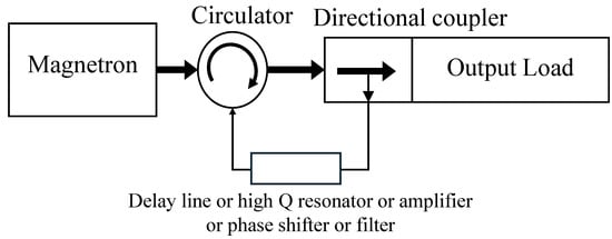
Figure 1.
Self-injection-locked magnetron from reference [55].
Reference [60] shows the master–slave injection method, in which the “slave magnetron” provides the injected signal, and the magnetron is injected and locked as the “master magnetron”. Mutual or peer-to-peer injection locking is similar to the master–slave injection method, which utilizes the output of one magnetron to drive another [58,59]. The two devices can achieve bidirectional mutual locking or operate in a master–slave configuration. Reference [58] performed an experiment on peer-to-peer locking of two 2-kW magnetrons and showed that the two nonlinear magnetrons may be locked to a common frequency.
Master–slave injection locking was experimentally verified in [30] using the two 2.45 GHz 800 W CW magnetrons as phase locking in a reflection amplifier. In reference [60], two Panasonic 2M244-M1 magnetrons based on master–slave injection-locking were demonstrated.
Although the aforementioned injection-locking techniques significantly enhance output stability, the energy oscillates in a narrow frequency band, which is not concentrated at a single frequency point, and the precise phase control is difficult. To attain higher phase precision, external auxiliary control is essential. This is typically realized by combining external reference-signal injection with closed-loop feedback adjustment of operating parameters—primarily the anode high voltage, and in some cases the magnetic field or filament current—thereby enabling precise amplitude and phase regulation. A comparison of the various magnetron injection-locking methods is provided in Table 1.

Table 1.
The injection-locked methods of magnetron.
2.3. Phase-Locked CW Magnetron
2.3.1. Phase-Locked of Magnetron
To achieve high-precision phase control, an external reference signal exhibiting excellent frequency and phase stability is required. This low-power signal is injected into the magnetron, enabling it to produce a high-power output with locked frequency and phase. Phase-locked magnetrons are primarily employed in microwave wireless power transfer (WPT) and coherent power combining applications. The foundational injection-locking system for magnetrons was proposed by W. C. Brown et al. [45]. Brown further developed the concept by inventing a novel crossed-field vacuum-tube amplifier, termed the “extended interaction tube” or crossed-field amplifier (CFA), which effectively transforms the magnetron from an oscillator into a power amplifier while retaining perpendicular electric and magnetic fields.
Extensive research on magnetron-based wireless power transfer has been conducted by Prof. N. Shinohara’s group at Kyoto University, Japan, with particular emphasis on injection locking of commercial Panasonic S-band and C-band magnetrons [4,61,62]. In ref. [61], a PLL-like feedback architecture was employed; a stable reference signal, phase-adjusted via a phase shifter, was injected into the magnetron. Figure 2 depicts its operation as a reflective amplifier suitable for coherent radar systems, where the injected signal power is typically 10–13 dB below the magnetron output. Shinohara’s team has also applied magnetrons as transmitters in space solar power system (SSPS) experiments. Given the significantly higher cost of semiconductor amplifiers compared with vacuum tubes, ref. [62] proposed an efficient phase- and amplitude-controlled magnetron (PACM) and a PACM-based near-field phased-array architecture tailored for SSPS.
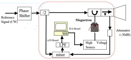
Figure 2.
Phase-controlled magnetron system [61].
Phase-control accuracy is critical for magnetron locking, multi-source power combining, and phased-array formation. Multiple studies have shown that the phase deviation of the injection-locked magnetron output gradually increases with the increase in the deviation between the injection signal frequency (at the same injection ratio) and the center frequency of the magnetron injection-locked bandwidth [64,65,66]. Prof. C. Liu’s team at Sichuan University, China, has performed systematic investigations into injection locking and power combining of high-power continuous-wave (CW) magnetrons as shown in Figure 3 [64,65,67,68]. In ref. [64], the phase stability of a 20 kW S-band CW magnetron was characterized under external injection. With 150 W injected power and approximately 19 kW output, the maximum phase deviation ranged from 1° to 6° across the locking band. In 2021, the team reported a 20 kW S-band injection-locked magnetron achieving a record-low injected power of only 3 W and phase noise of −85 dBc/Hz at 50 kHz offset—the best reported performance for S-band magnetrons exceeding 20 kW output [65]. Additional contributions include work by S. Fujii et al., who demonstrated injection locking of a Panasonic 2M137A-01BTM magnetron using an external oscillator with an injection ratio of −26 dB [66]. X. Chen et al. investigated an external oscillator injection-locked 5.8-GHz magnetron system and established the equivalent circuit model [69]. As depicted in Figure 4, H. Huang et al. demonstrated a 5.8 GHz phase-locked magnetron system in which the measured phase fluctuation of the injection-locked magnetron was approximately ±2.5° under open-loop conditions and reduced to approximately ±0.5° when closed-loop phase-locked-loop control was activated, thereby confirming effective phase stabilization [11]. These results collectively highlight the considerable potential of external injection-locked magnetrons for scalable high-power coherent systems. A summary of key parameters and performance metrics of representative externally injection-locked magnetrons is presented in Table 2.
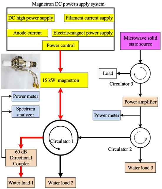
Figure 3.
Block diagram of an injection-locked 15 kW magnetron system [65]. Red arrows is the direction of large power output of the magnetron.
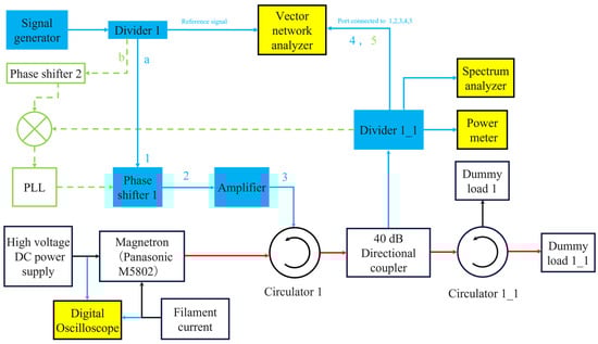
Figure 4.
A 5.8-GHz phase-locked magnetron system [11]. Blue number 1,2,3,4,5 is the measurement position.
Table 2.
Summary of external injection-locked magnetron systems.
2.3.2. Phase-Locked CW Magnetron for Accelerator
Proton accelerators typically require RF source phase stability of 1–2°, whereas electron accelerators demand 0.1–0.2° [71]. Although magnetrons offer high efficiency, low cost, and compactness, they have rarely been adopted in high-energy accelerators owing to insufficient inherent frequency and phase stability. Significant improvement in magnetron phase stability would enable their practical use in accelerator applications.
Injection locking of pulsed magnetrons has been extensively investigated for accelerators [33,72,73,74]. In one early approach, the output of a tetrode amplifier was employed as the injection signal to phase-lock a magnetron, producing RF pulses suitable for accelerator requirements [46].
Accelerator-grade injection-locked magnetrons usually require auxiliary high-stability sources such as traveling-wave tubes (TWTs) or superconducting RF cavities [75]. A. C. Dexter’s group at Lancaster University, U.K., systematically explored injection-locked magnetrons as a cost-effective alternative to conventional high-power microwave sources for superconducting linear accelerators [31,76,77]. I. Tahir et al. demonstrated injection locking of a commercial 2.45 GHz microwave-oven magnetron using a continuous-wave (CW) scheme with a 40 dB injection ratio and DSP-assisted feedback control (experimental arrangement [76]. In 2011, Dexter’s team reported the first successful use of an injection-locked magnetron for active phase control of a superconducting cavity [78]. A 704 MHz, 440 kW CW magnetron was paired with a niobium superconducting cavity, achieving frequency control to within 3 Hz, independent amplitude and phase regulation, and peak-to-peak phase fluctuation of 2° (0.95° rms) [78].
A two-stage injection-locked CW magnetron system was developed by G. Kazakevich et al. at Fermilab to drive superconducting cavities in the proposed Project-X intensity-frontier accelerator [10,75,79]. As illustrated in Figure 5, a 1 kW CW S-band magnetron, injection-locked in two stages, served as the RF source for the 1.3 GHz superconducting cavities of an 8 GeV pulsed linac [79]. Testing confirmed that such magnetically primed sources could substantially reduce capital costs compared with traditional klystrons, inductive output tubes (IOTs), or solid-state amplifiers [10].
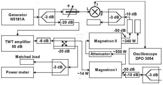
Figure 5.
The injection-locked two-stage CW magnetron [79].
Subsequent work demonstrated a 2.45 GHz CW injection-locked magnetron providing vector control for a superconducting RF (SRF) cavity, achieving 30 dB amplitude dynamic range, 0.3% rms amplitude stability, and 0.26° rms phase stability [80]. Further advances in magnetron control techniques tailored for SRF accelerators were experimentally validated in [81].
These results collectively establish that injection-locked magnetrons can meet or approach the stringent phase-stability requirements of modern superconducting accelerators, offering a highly cost-effective alternative to conventional RF sources.
2.3.3. Injection-Locked Magnetron Modulator
Precise phase control of injection-locked magnetrons provides the fundamental prerequisite for implementing various modulation schemes. Extensive research on magnetron-based modulation has been conducted by Y. Yang et al. at Kyoto University [5,17,25,82,83]. As illustrated in Figure 6 [82], a frequency-shift-keying (FSK) modulator operating near the magnetron’s natural oscillation frequency was employed in [82]. The modulated signal was amplified to 10 W and injected into a Panasonic M5802 magnetron via a circulator. This configuration enables simultaneous wireless power transfer and data communication using amplitude, phase, or frequency modulation. A reliable data rate of 9600 bps with zero bit errors was achieved, demonstrating that an injection-locked magnetron functioning as a power amplifier exhibits excellent controllability [82].
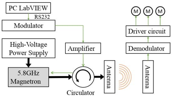
Figure 6.
FSK modulation and injection-locking scheme for simultaneous power and data transmission [82].
In [83], an injection-locked 2.45 GHz continuous-wave (CW) magnetron was utilized in a wirelessly powered television system (shown in Figure 7). At the transmitter, frequency modulation was applied to the injection-locked magnetron to encode video signals while delivering microwave power. At the receiver, the incident microwave energy was simultaneously rectified to provide 48 W of DC power and demodulated to recover the video signal, achieving a wireless range of 3.5 m [83].
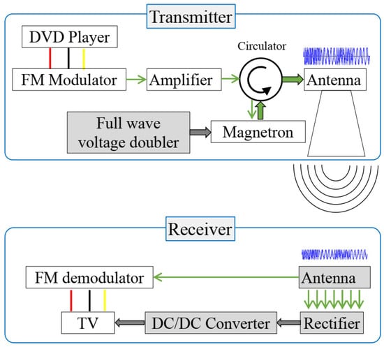
Figure 7.
Diagram of wireless-powered TV system based on magnetron [83].
A four-element phased-array system employing 5.8 GHz injection-locked magnetrons was demonstrated in [84], delivering a maximum microwave output of 1637 W while supporting simultaneous wireless information and power transfer (SWIPT). Under various modulation rates, the measured power transmission efficiency fluctuated by less than 0.5%. Frequency-modulated camera video signals were successfully transmitted and decoded, confirming the robust performance of the injection-locked magnetron array in joint power-and-information transfer applications [84].
These results collectively establish that injection-locked magnetrons can serve as highly controllable, high-power transmitters capable of supporting advanced modulation formats for integrated wireless power and communication systems.
Unlike the injection-locked magnetron system described in Section 2.2, which operates primarily within a narrow bandwidth, the phase-locked magnetrons presented in Section 2.3 provide precise control of frequency, phase, and amplitude. These systems further enable magnetron modulation capabilities.
Phase-locked configurations typically utilize a single-magnetron injection-locked architecture, where the output power capacity is limited by the efficiency of the individual magnetron. However, if multiple magnetrons can be synchronized to the same frequency and phase, power combining in a multi-magnetron system becomes feasible. This approach allows the total output power to exceed the limit of a single magnetron.
Achieving injection locking across multiple magnetrons requires preliminary screening of a larger pool of devices to select those exhibiting similar locking characteristics. This selection process is essential for successful power combining but increases the overall system scale and integration complexity. In Section 3, multi-magnetron injection-locked systems are reviewed.
3. Power Combining of Multiple Magnetrons
3.1. Injection-Locked Magnetron Power Combining Based on Waveguides
In industrial applications, the per-unit cost of commercially manufactured continuous-wave (CW) magnetrons rated above 1 kW is substantially higher than that of typical microwave-oven magnetrons. The highest reported output powers for single CW magnetrons in the three principal ISM bands used for microwave heating are approximately 300 kW (L-band), 30 kW (S-band), and 1 kW (C-band), respectively [68,85]. S-band and C-band magnetrons have attracted the majority of research attention for WPT applications and microwave heating [12,16].
Microwave power-combining technology employing multiple synchronized sources has been widely adopted in high-power microwave communication, remote sensing, electronic countermeasures, WPT, SSPS, plasma heating, superconducting particle accelerators, and industrial microwave processing [16,58,67].
As the demand for multi-kilowatt and megawatt-class microwave sources continues to grow, individual magnetrons are approaching their fundamental power-handling limits, making coherent power combining using multiple oscillators a key research focus [68,86,87]. The prerequisite for efficient power combining is that all sources operate at identical frequency and maintain a stable, controllable phase relationship [88]. Injection locking provides a highly effective synchronization technique for magnetrons: a common low-power reference signal (or mutual coupling between magnetrons) locks the phase of each oscillator, after which the individual outputs are coherently summed using waveguide combiners, hybrid couplers, or resonant structures to achieve near-theoretical combining efficiency.
During their wireless power transmission research, Prof. N. Shinohara’s group at Kyoto University successfully demonstrated both power combining and phased-array operation using arrays of commercial magnetrons. Earlier, in the 20th century, coherent power combining of high-power injection-locked pulsed magnetrons was investigated for particle accelerator applications [89,90].
A pioneering result was reported by T. A. Treado et al. in 1994, who achieved 96% combining efficiency—the first demonstration of highly efficient combining of microwave power from two phase-locked long-pulse or CW magnetrons [90]. A. C. Dexter et al. [78] demonstrated an amplitude control scenario using two injection-locked magnetrons shown in Figure 8. By precisely adjusting the effective phase difference between the outputs of the two magnetrons, they controlled both the effective phase difference and the attenuation of the radio RF amplitude to a superconducting accelerator cavity.
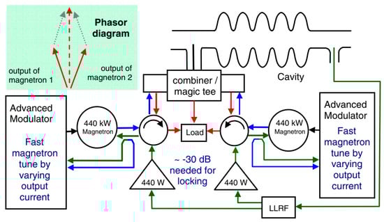
Figure 8.
Power combining of two magnetrons with a variable phase offset [78].
To overcome the power limitations of single microwave sources in demanding industrial processes—such as microwave plasma chemical vapor deposition (MPCVD) for diamond thin-film synthesis—Prof. C. Liu’s team at Sichuan University has conducted extensive research on coherent power combining using injection-locked magnetrons.
In 2015, they developed and experimentally validated a two-magnetron S-band coherent power-combining system employing 15 kW CW injection-locked magnetrons, achieving combining efficiencies exceeding 95% [67]. As shown in Figure 9, one magnetron’s output phase is actively controlled via a digital phase shifter, while a phase detector continuously monitors the relative phase difference between the two sources [67,68].
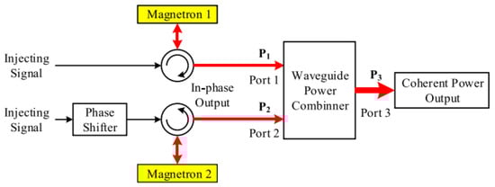
Figure 9.
The power combining system based on two S-band injection-locked 15 kW CW magnetrons [68].
Subsequent work reported a four-magnetron S-band array using 20 kW hybrid injection-locked magnetrons, delivering a total coherent output power greater than 60.6 kW with a combining efficiency of 91.5%—setting a performance record for S-band magnetron-based systems at that time [91]
Reference [92] experimentally demonstrated a microwave power-combining system that leverages the power-splitting characteristics of a magic-T junction to achieve mutual injection locking of two 1 kW S-band magnetrons. By adjusting the operating frequency to control the relative phase difference between the two magnetron outputs, the system enables high-efficiency dual-path coherent power combining. Measured results confirm a combining efficiency of 94.5%.
Another innovative design utilized an asymmetric H-plane T-junction combiner with closed-loop phase compensation (CLPC), enabling two magnetrons to be frequency-locked using only a single external injector through port coupling. This configuration achieved a maximum combining efficiency of 95.7% [93].
At 5.8 GHz, a high-efficiency four-way power-combining architecture based on a non-isolated, lossless five-port waveguide hybrid combiner was demonstrated in [11]. Experimental results showed that injection-locked operation without an external PLL yielded combining efficiencies above 95%, with a peak efficiency of 97.7% attained through precise phase control of the injected signals.
A summary of the key parameters and performance of the aforementioned phase-locked magnetron power-combining systems is presented in Table 3.
Table 3.
Power combining system parameter of phase-locked magnetron systems.
3.2. CW Magnetron Active Phased Array for WPT
Due to the inherent power-capacity limitations of individual microwave sources, phased-array technology is widely employed to coherently combine the outputs of multiple sources, thereby significantly increasing the total transmitted microwave power [7,36,61].
For SSPS applications, the development of efficient, large-scale, high-precision, lightweight, and low-cost phased-array antennas has become a primary research focus [15]. In recent years, Prof. N. Shinohara’s group at Kyoto University has achieved breakthrough progress in magnetron-based phased arrays by arranging multiple phase-controllable magnetrons in array configurations. The key advantage of this approach lies in the independent amplitude and phase control of each magnetron, which enables not only highly efficient power combining but also flexible electronic steering and spatial shaping of the microwave beam [16,36].
Shinohara et al. have systematically investigated high-power PLL-based magnetron control techniques to support SSPS requirements, successfully demonstrating precise amplitude and phase regulation of magnetrons operating at 2.45 GHz and 5.8 GHz [15,17,61]. This advancement has transformed the magnetron from a conventional autonomous high-power oscillator into a fully controllable element suitable for large-scale phased-array systems [9].
In an early demonstration, an active phased-array experiment using two injection-locked 2M236 magnetrons (shown in Figure 2) was reported in [61]. By coherently combining the outputs of two active antenna elements (illustrated in Figure 10) and applying phase-controlled magnetron (PCM) technology, beam steering of the main lobe was achieved over a range of 80–90° through adjustment of the magnetron output phases, thereby validating precise pointing control of the array.
Figure 10.
H-plane sectoral horns with PCMs [61].
To mitigate power losses caused by the injection-locked toroidal unit in the PCM system and reduce the requirement for a dedicated phase shifter in every array element, reference [9] proposed and experimentally demonstrated a beam direction control based on a mutually injection-locked magnetron phased array. As shown in Figure 11, only two PCM units are equipped with phase shifters, while the remaining elements operate as self-oscillated and mutually injection-locked magnetrons. This configuration enables beam direction control of the magnetron phased array with significantly reduced hardware complexity [9].
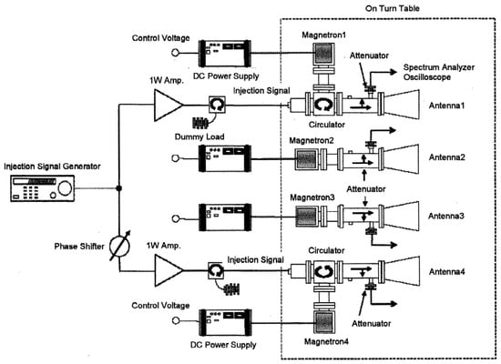
Figure 11.
Experimental setup from [9].
A four-element phased-array system combining injection-locking and PLL techniques was demonstrated in [12]. The array consisted of power-variable PCMs feeding a waveguide slot-array antenna. At a total microwave output of 1304 W, 142 W of DC power was received at a 5 m distance, confirming effective coherent power combining and energy transmission performance [12].
Figure 12 presents the block diagram of a 5.8 GHz magnetron phased-array system. The simultaneous wireless information and power transfer (SWIPT) comprises four power- and phase-controllable magnetrons arranged in a 2 × 2 configuration [84]. In this SWIPT implementation, the main lobe delivers microwave power, while encoded information can be successfully demodulated across a wide angular range from −90° to +90° in front of the array. The maximum transmitted microwave power achieved by the system is 1637 W.
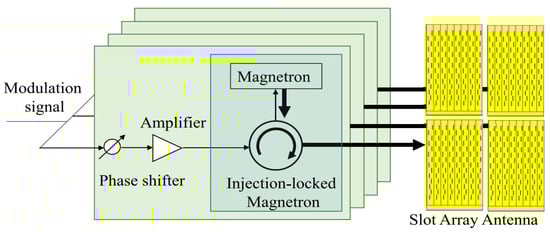
Figure 12.
Block diagram of the magnetron phased array system [84].
In Section 2 and Section 3, research and applications of magnetron injection locking systems primarily addressed the issue of unstable output signals from free-running magnetrons. The investigations focused on the feasibility of achieving injection locking in the magnetron itself and on evaluating the stability and performance of the output signal following locking.
4. Next-Generation Magnetron Prospects
4.1. Innovative Operations of CW Magnetron
As system scale and complexity increase, the associated control challenges also escalate. For practical deployment, microwave source systems that offer simplicity, compactness, and higher-power-handling capacity provide significant advantages. Both industrial microwave heating and WPT systems prioritize lightweight designs to improve overall efficiency and feasibility. Recent novel applications of magnetrons have generated increased research interest in enhancing the inherent stability of next-generation magnetron designs.
Conventional injection-locked magnetron systems require a waveguide circulator for signal injection, which introduces significant size and weight penalties. To overcome this limitation, S. Wang et al. [94] proposed and experimentally demonstrated a novel circulator-free injection-locking technique whereby microwave power is directly injected through the magnetron cathode (filament). In this approach, the magnetron is treated as a two-port device, with the filament structure serving as the injection port. As illustrated in Figure 13, the injection signal is coupled into the magnetron filter box via a designed monopole probe or coupling ring. This method completely eliminates the need for bulky waveguide circulators or directional couplers between the injection source and the magnetron, resulting in a compact, low-cost injection-locked system. Experimental results showed a maximum locking bandwidth of 0.7 MHz at an injection ratio of 0.2, with reductions of 28% in weight and 16% in volume compared with conventional configurations [94]. This breakthrough is expected to significantly simplify the architecture of injection-locked magnetron systems, particularly in large-scale multi-magnetron arrays.
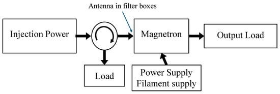
Figure 13.
Photographs of modified magnetron filter boxes [94].
Industrial 1 kW CW S-band magnetrons are widely available at very low cost. Y. Chernousov et al. [95] first proposed and demonstrated the operation of such a commercial CW magnetron in high-power pulsed mode. The device successfully operated as a pulsed magnetron in both free-running and injection-locked regimes, achieving peak output powers up to 8 kW, pulse widths ranging from 0.3 µs to continuous mode, and repetition frequencies at least 1 MHz [95]. This innovative operating mode substantially expands the application area of low-cost CW magnetrons and, when combined with injection-locking and modulation techniques, offers a highly cost-effective route to cost-effective pulsed microwave sources.
4.2. Prospects of the Next-Generation Magnetron
Driven by emerging high-power applications—including microwave materials processing, microwave sintering, space solar power stations (SSPS), particle accelerators, and large-scale wireless power transfer—the research focus on continuous-wave (CW) magnetrons has shifted toward achieving higher output power, improved amplitude/frequency/phase stability, greater efficiency, extended operational lifespan, reduced cost, and developing innovative applications [14,96].
To enhance the inherent stability and controllability of CW magnetrons, two complementary strategies are being pursued:
- (1)
- Device-level improvements:
These include optimized resonant-cavity designs, advanced cathode materials [97,98], novel anode-block geometries, and structural modifications (for instance, Amplitron-like configurations) aimed at fundamentally reducing frequency pushing/pulling effects and improving intrinsic spectral purity.
- (2)
- External operating-parameter control:
Primarily realized through injection-locking techniques combined with real-time feedback of anode voltage, magnetic field, or filament current.
The short filament lifetime remains a critical limitation for long-duration missions such as SSPS. Replacement of conventional thermionic cathodes with cold-cathode technology could extend magnetron lifetime beyond 40,000 h, making it highly attractive for space-based WPT systems [99].
Future magnetron development is expected to emphasize higher operating frequencies, longer lifespan, higher efficiency, and significantly improved amplitude–frequency–phase stability [14,96].
Highly integrated injection-locking and power-combining architectures offer another promising direction. Early investigations by the Physics International Group on phase-locked relativistic magnetrons [100,101,102] demonstrated that maximum-connectivity array topologies minimize lock-in time. For instance, a seven-magnetron array coupled via waveguides achieved a coherent output of 3 GW, with lock-in dynamics comparable to two-magnetron experiments [100]. The concept of integrating multiple injection-locked magnetrons into a single resonant cavity, originally proposed in [100], is equally applicable to CW systems. It could substantially reduce size, weight, and complexity while enhancing the combining efficiency. With the development of next-generation magnetrons, microwaves will find more and more applications across various fields.
5. Conclusions
Despite remarkable progress in semiconductor technology, vacuum electronic devices continue to play an indispensable role in applications that demand extremely high power and efficiency. This paper reviews the historical development and current research trends in magnetrons, with particular emphasis on injection-locked (injection-synchronized) magnetrons. The maturation of frequency- and phase-stabilization techniques has dramatically enhanced their performance, establishing injection-locked magnetrons as one of the most cost-effective solutions for high-power, high-efficiency microwave generation.
Using the injection-locking method, a magnetron system can operate primarily within a narrow bandwidth. Subsequent phase-locking with an external reference signal enables precise control of frequency, phase, and amplitude. If multiple phase-locked magnetrons are synchronized to the same frequency and phase, power combining is possible, allowing the total output power to exceed that of a single magnetron. However, as the scale and complexity of the magnetron system increase, the associated control challenges escalate accordingly. Research on long-term phase stability, fault tolerance, and overall system reliability remains limited.
The application domain of magnetrons is rapidly expanding beyond traditional microwave heating and radar systems to include WPT, SSPS, particle accelerators, advanced materials processing, and large-scale industrial microwave systems. Looking forward, continued innovation in vacuum-tube design—such as cold-cathode implementations, novel cavity geometries, and highly integrated multi-magnetron arrays—combined with strategic hybrid integration with solid-state devices, is expected to yield next-generation microwave sources that simultaneously achieve exceptional efficiency, long operational lifetime, and precise amplitude–frequency–phase stability. These advances will position injection-locked magnetrons as an important technology for realizing a sustainable, high-power microwave energy society.
Author Contributions
Conceptualization, H.H. and B.Y.; writing—original draft preparation, H.H.; writing—review and editing, B.Y. and N.S.; funding acquisition, H.H., B.Y. and N.S. All authors have read and agreed to the published version of the manuscript.
Funding
This research was funded by NSFC under grant number 62001402.
Data Availability Statement
No new data were created or analyzed in this study. Data sharing is not applicable to this article.
Acknowledgments
Heping Huang’s work is supported by the School of Low-Altitude Economy and Industry, Southwest Minzu University. This work was supported in part by the Microwave Energy Transmission Laboratory, Research Institute for Sustainable Humanosphere, Kyoto University.
Conflicts of Interest
The authors declare no conflicts of interest.
References
- Gilmour, A.S. Microwave and Millimeter-Wave Vacuum Electron Devices: Inductive Output Tubes, Klystrons, Traveling-Wave Tubes, Magnetrons, Crossed-Field Amplifiers, and Gyrotrons; Artech: Tokyo, Japan, 2020. [Google Scholar]
- Changjun, L. Microwave—A New Open Access Journal for Microwave Technologies. Microwave 2025, 1, 1. [Google Scholar] [CrossRef]
- Mitani, T.; Shinohara, N.; Matsumoto, H.; Aiga, M.; Kuwahara, N.; Handa, T. Time domain analysis of noises generated from microwave oven magnetron. Electron. Commun. Jpn. Pt. II-Electron. 2005, 88, 28–36. [Google Scholar] [CrossRef]
- Yang, B.; Mitani, T.; Shinohara, N.; Zhang, H. High-Power Simultaneous Wireless Information and Power Transfer: Injection-Locked Magnetron Technology. ZTE Commun. 2022, 20, 10. [Google Scholar]
- Yang, B.; Mitani, T.; Shinohara, N. Experimental study on frequency modulation of an injection-locked magnetron based on full wave voltage doubler. In Proceedings of the 2018 IEEE International Vacuum Electronics Conference (IVEC), Monterey, CA, USA, 24–26 April 2018; pp. 251–252. [Google Scholar]
- Middleton, D.; Gottschalk, W.M.; Wiesner, J.B. Noise in CW Magnetrons. J. Appl. Phys. 1953, 24, 1065–1066. [Google Scholar] [CrossRef]
- Shinohara, N.; Matsumoto, H. Design of space solar power system (SSPS) with phase and amplitude controlled magnetron. In Proceedings of the 2004 Asia-Pacific Radio Science Conference, Qingdao, China, 24–27 August 2004; pp. 624–626. [Google Scholar]
- Mitani, T.; Kawasaki, H.; Shinohara, N.; Matsumoto, H. A Study of Oven Magnetrons toward a Transmitter for Space Applications. In Proceedings of the 2009 IEEE International Vacuum Electronics Conference, Rome, Italy, 28–30 April 2009; pp. 323–324. [Google Scholar]
- Shinohara, N.; Matsumoto, H. Research of Magnetron Phased Array with Mutual Injection Locking for Space Solar Power Satellite/Station. Electr. Eng. Jpn. 2010, 173, 21–32. [Google Scholar] [CrossRef]
- Kazakevich, G.; Johnson, R.; Flanagan, G.; Marhauser, F.; Yakovlev, V.; Chase, B.; Nagaitsev, S.; Pasquinelli, R.; Wolff, D. High-Power Magnetron RF Source For Superconducting Linacs of ADS and Intensity-Frontier Projects; Fermi National Accelerator Laboratory (FNAL): Batavia, IL, USA, 2013.
- Huang, H.; Yang, B.; Shinohara, N.; Liu, C. Coherent Power Combining of Four-Way Injection-Locked 5.8-GHz Magnetrons Based on a Five-Port Hybrid Waveguide Combiner. IEEE Trans. Microw. Theory Tech. 2024, 72, 4395–4404. [Google Scholar] [CrossRef]
- Yang, B.; Chen, X.; Chu, J.; Mitani, T.; Shinohara, N. A 5.8-GHz Phased Array System Using Power-Variable Phase-Controlled Magnetrons for Wireless Power Transfer. IEEE Trans. Microw. Theory Tech. 2020, 68, 4951–4959. [Google Scholar] [CrossRef]
- Mitani, T. Microwave tube transmitters. In Recent Wireless Power Transfer Technologies via Radio Waves, Proceedings of the Sixth International Vacuum Electronics Conference IVEC, Monterey, CA, USA, 25–29 April 2022; River Publishers: Aalborg, Denmark, 2022; pp. 49–69. [Google Scholar]
- Shinohara, N. Trends in Wireless Power Transfer: WPT Technology for Energy Harvesting, Millimeter-Wave/THz Rectennas, MIMO-WPT, and Advances in Near-Field WPT Applications. IEEE Microw. Mag. 2021, 22, 46–59. [Google Scholar] [CrossRef]
- He, H.; Liao, C.; He, Z.; Yan, L.; Liu, C. High-Efficiency Ultrawideband Microwave Rectifier Based on Adaptive Harmonic Control. IEEE Trans. Microw. Theory Tech. 2025, 73, 10017–10027. [Google Scholar] [CrossRef]
- Shinohara, N.; Matsumoto, H.; Hashimoto, K. Phase-controlled magnetron development for SPORTS: Space power radio transmission system. URSI Radio Sci. Bull. 2004, 2004, 29–35. [Google Scholar] [CrossRef]
- Mitani, T.; Shinohara, N.; Matsumoto, H. Development of a pulse-driven phase-controlled magnetron. In Proceedings of the Eighth IEEE International Vacuum Electronics Conference, Kitakyushu, Japan, 15–17 May 2007; pp. 425–426. [Google Scholar]
- Mitani, T.; Shinohara, N.; Hashimoto, K. A Fundamental Study on Spectral Purity of a CW Magnetron for Microwave Power Transmission. In Proceedings of the XXIX URSI General Assembly, Chicago IL, USA, 7–16 August 2008. [Google Scholar]
- Collins, G.B. Microwave Magnetrons; McGraw-Hill: New York, NY, USA, 1948; Volume 6. [Google Scholar]
- Hull, A.W. The magnetron. Am. Inst. Electr. Eng. J. 1921, 40, 715–723. [Google Scholar] [CrossRef]
- Pengvanich, P. Theory of Injection Locking and Rapid Start-Up of Magnetrons, and Effects of Manufacturing Errors in Terahertz Traveling Wave Tubes. Ph.D. Thesis, The University of Michigan, Ann Arbor, MI, USA, 2007. [Google Scholar]
- Welch, H.W. Prediction of Traveling Wave Magnetron Frequency Characteristics: Frequency Pushing and Voltage Tuning. Proc. IRE 1953, 41, 1631–1653. [Google Scholar] [CrossRef]
- Zhang, Z.; Zhou, Y.; Lai, S.; Wang, G.; Zhu, H.; Yang, Y. Influence of Power Supply Ripple on Injection Locking of Magnetron with Frequency Pushing Effect. Processes 2022, 10, 2124. [Google Scholar] [CrossRef]
- Neculaes, V.B.; Jones, M.C.; Gilgenbach, R.M.; Lau, Y.Y.; Luginsland, J.W.; Hoff, B.W.; White, W.M.; Jordan, N.M.; Pengvanich, P.; Hidaka, Y.; et al. Magnetic priming effects on noise, startup, and mode competition in magnetrons. IEEE Trans. Plasma Sci. 2005, 33, 94–102. [Google Scholar] [CrossRef]
- Yang, B.; Mitani, T.; Shinohara, N. Evaluation of the Modulation Performance of Injection-Locked Continuous-Wave Magnetrons. IEEE Trans. Electron Devices 2019, 66, 709–715. [Google Scholar] [CrossRef]
- Mitani, T.; Shinohara, N.; Matsumoto, H.; Hashimoto, K. Experimental study on oscillation characteristics of magnetron after turning off filament current. Electron. Commun. Jpn. (Part II Electron.) 2003, 86, 1–9. [Google Scholar] [CrossRef]
- Brown, W.C. The high signal to noise ratio of the microwave oven magnetron and evidence of a negative feedback loop to control it. In Proceedings of the 1st International Workshop Crossed-Field Devices, Ann Arbor, MI, USA, 15–16 August 1995; pp. 178–187. [Google Scholar]
- Neculaes, V.B.; Jones, M.C.; Gilgenbach, R.W.; Lau, Y.Y.; Luginsland, J.W.; Hoff, B.W.; White, W.M.; Jordan, N.M.; Pengvanich, P.; Hidaka, Y.; et al. Magnetic perturbation effects on noise and startup in DC-operating oven magnetrons. IEEE Trans. Electron Devices 2005, 52, 864–871. [Google Scholar] [CrossRef]
- Adler, R. A study of locking phenomena in oscillators. Proc. IRE 1946, 34, 351–357. [Google Scholar] [CrossRef]
- Pengvanich, P.; Neculaes, V.B.; Lau, Y.Y.; Gilgenbach, R.M.; Jones, M.C.; White, W.M.; Kowalczyk, R.D. Modeling and experimental studies of magnetron injection locking. J. Appl. Phys. 2005, 98, 114903. [Google Scholar] [CrossRef]
- Tahir, I.; Dexter, A.; Carter, R. Frequency and phase modulation performance of an injection-locked CW magnetron. IEEE Trans. Electron Devices 2006, 53, 1721–1729. [Google Scholar] [CrossRef]
- Pengvanich, P.; Lau, Y.Y.; Luginsland, J.W.; Gilgenbach, R.M.; Cruz, E.; Schamiloglu, E. Effects of frequency chirp on magnetron injection locking. Phys. Plasmas 2008, 15, 073110. [Google Scholar] [CrossRef]
- De Vito, P.; Kearns, W.; Seavey, M. Phase pattern control of injection-locked pulsed magnetrons. Proc. IEEE 1969, 57, 1436–1437. [Google Scholar]
- Slater, J.C. The Phasing of Magnetrons; Technical Report NO. 35; Massachusetts Institute of Technology: Cambridge, MA, USA, 1947. [Google Scholar]
- Simon, D.H.; Lau, Y.Y.; Greening, G.; Wong, P.; Hoff, B.W.; Gilgenbach, R.M. Stability of Brillouin flow in planar, conventional, and inverted magnetrons. Phys. Plasmas 2015, 22, 082104. [Google Scholar] [CrossRef]
- Stephan, K.D. Inter-injection-locked oscillators for power combining and phased arrays. Microw. Theory Tech. IEEE Trans. 1986, 34, 1017–1025. [Google Scholar]
- Paciorek, L.J. Injection locking of oscillators. Proc. IEEE 1965, 53, 1723–1727. [Google Scholar] [CrossRef]
- David, E.E. RF phase control in pulsed magnetrons. Proc. IRE 1952, 40, 669–685. [Google Scholar] [CrossRef]
- Seavey, M.H. Some properties of an injection-locked pulsed magnetron in a coherent-echo-detection system. Electron. Lett. 1967, 3, 375–377. [Google Scholar] [CrossRef]
- Devito, P.A. Some Properties of an Injection-Locked Pulsed Magnetron; DTIC Document: Fort Belvoir, VA, USA, 1973. [Google Scholar]
- Brown, W.C. The microwave magnetron and its derivatives. Electron Devices IEEE Trans. 1984, 31, 1595–1605. [Google Scholar] [CrossRef]
- Brown, W.C. Phase-Locked Magnetron System. U.S. Patent 4571552A, 18 February 1986. [Google Scholar]
- Brown, W.C. Magnetron Amplifier Power Combiner. U.S. Patent 4634992A, 6 January 1987. [Google Scholar]
- Brown, W.C. Magnetron Amplifier. U.S. Patent 2673306A, 6 July 1954. [Google Scholar]
- Brown, W.C. The Magnetron—A Low Noise, Long Life Amplifier. Appl. Microw. 1990, 117, 5. [Google Scholar]
- Overett, T.; Remsen, D.; Bowles, E.; Thomas, G.; Smith, R., III. Phase Locked Magnetrons as Accelerator RF Sources. In Proceedings of the 12th IEEE Particle Accelerator Conference, Washington, DC, USA, 16–19 March 1987. [Google Scholar]
- Benford, J.; Smith, R.R.; Sze, H.; Harteneck, B.; Woo, W. Phase-locking of relativistic magnetrons. In Proceedings of the Microwave and Particle Beam Sources and Propagation, Los Angeles, CA, USA, 13–15 January 1988; pp. 23–27. [Google Scholar]
- Benford, J.; Sze, H.; Woo, W.; Smith, R.R.; Harteneck, B. Phase locking of relativistic magnetrons. Phys. Rev. Lett. 1989, 62, 969–971. [Google Scholar] [CrossRef]
- Levine, J.S.; Benford, J.; Cooksey, N.; Harteneck, B.; Smith, R.R.; Sze, H. Phase-locking of multiple relativistic magnetrons. In Proceedings of the IEEE 1989 International Conference on Plasma Science, Buffalo, NY, USA, 22–24 May 1989; p. 122. [Google Scholar]
- Chen, S.C.; Bekefi, G.; Temkin, R.J. Injection locking of a long-pulse relativistic magnetron. In Proceedings of the 1991 IEEE Particle Accelerator Conference, San Francisco, CA, USA, 6–9 May 1991; pp. 751–753. [Google Scholar]
- Strassner, B.; Chang, K. Microwave Power Transmission: Historical Milestones and System Components. Proc. IEEE 2013, 101, 1379–1396. [Google Scholar] [CrossRef]
- Metaxas, A.C.; Meredith, R.J. Industrial Microwave Heating; The Institution of Engineering and Technology: London, UK, 1988; p. 376. [Google Scholar]
- Hasegawa, N.; Fujiwara, T.; Morita, T.; Kishimoto, A.; Hasegawa, K.; Takagi, Y.; Ohta, Y. Phase-Locked Magnetrons for Beam Combining in High Power Antenna Array on MPT System. In Proceedings of the 2019 IEEE Asia-Pacific Microwave Conference (APMC), Singapore, 10–13 December 2019; pp. 905–907. [Google Scholar]
- Neubauer, M.; Popovic, M.; Johnson, R.P. Phase and Frequency locked magnetron. In Proceedings of the IPAC2012, New Orleans, LA, USA, 20–25 May 2012. [Google Scholar]
- Heng-Chia, C. Stability analysis of self-injection-locked oscillators. IEEE Trans. Microw. Theory Tech. 2003, 51, 1989–1993. [Google Scholar] [CrossRef]
- Heng-Chia, C. Phase noise in self-injection-locked oscillators—Theory and experiment. IEEE Trans. Microw. Theory Tech. 2003, 51, 1994–1999. [Google Scholar] [CrossRef]
- Zhang, Y.; Yuan, P.; Ye, W.; Zhu, H.; Yang, Y.; Huang, K. Frequency qusai locking and noise reduction of the self-injection qusai locked magnetron. Int. J. Appl. Electromagn. Mech. 2016, 51, 71–81. [Google Scholar] [CrossRef]
- Cruz, E.J.; Hoff, B.W.; Pengvanich, P.; Lau, Y.Y.; Gilgenbach, R.M.; Luginsland, J.W. Experiments on peer-to-peer locking of magnetrons. Appl. Phys. Lett. 2009, 95, 191503. [Google Scholar] [CrossRef]
- Pengvanich, P.; Lau, Y.Y.; Cruz, E.; Gilgenbach, R.M.; Hoff, B.; Luginsland, J.W. Analysis of peer-to-peer locking of magnetrons. Phys. Plasmas 2008, 15, 103104. [Google Scholar] [CrossRef]
- Yuan, P.; Zhang, Y.; Ye, W.; Zhu, H.; Huang, K.; Yang, Y. Power-combining based on master-slave injection-locking magnetron. Chin. Phys. B 2016, 25, 078402. [Google Scholar] [CrossRef]
- Shinohara, N.; Fujiwara, J.; Matsumoto, H. Development of active phased array with phase-controlled magnetrons. In Proceedings of the International Symposium on Antennas and Propagations, Beijing, China, 15–18 August 2000; pp. 713–716. [Google Scholar]
- Shinohara, N.; Matsumoto, H. Microwave power transmission system with phase and amplitude controlled magnetrons. In Proceedings of the International Conference on Recent Advances in Space Technologies, Istanbul, Turkey, 9–11 June 2005; pp. 28–33. [Google Scholar]
- Choi, J.J.; Choi, G.W. Experimental observation of frequency locking and noise reduction in a self-injection-locked magnetron. IEEE Trans. Electron Devices 2007, 54, 3430–3432. [Google Scholar] [CrossRef]
- Huang, H.; Huang, K.; Liu, C. Experimental Study on the Phase Deviation of 20-kW S-Band CW Phase-Locked Magnetrons. IEEE Microw. Wirel. Compon. Lett. 2018, 28, 509–511. [Google Scholar] [CrossRef]
- Liu, Z.; Cai, Z.; Pei, N.; Tan, Z.; Liu, C. Performance Evaluation of a 20-kW Injection-locked Magnetron with Load-Pull Characterization. In Proceedings of the 2021 IEEE MTT-S International Wireless Symposium (IWS), Nanjing, China, 23–26 May 2021; pp. 1–3. [Google Scholar]
- Fujii, S.; Maitani, M.M.; Suzuki, E.; Chonan, S.; Fukui, M.; Wada, Y. Injection-Locked Magnetron Using a Cross-Domain Analyzer. IEEE Microw. Wirel. Compon. Lett. 2016, 26, 966–968. [Google Scholar] [CrossRef]
- Huang, H.; Liu, L.; Huo, F.; Liu, Z.; Liu, C. Microwave power combining system based on two injection-locked 15 kW CW magnetrons. In Proceedings of the 2015 IEEE MTT-S International Microwave Symposium, Phoenix, AZ, USA, 17–22 May 2015; pp. 1–3. [Google Scholar]
- Liu, C.; Huang, H.; Liu, Z.; Huo, F.; Huang, K. Experimental Study on Microwave Power Combining Based on Injection-Locked 15-kW S-Band Continuous-Wave Magnetrons. IEEE Trans. Plasma Sci. 2016, 44, 1291–1297. [Google Scholar] [CrossRef]
- Chen, X.; Yang, B.; Shinohara, N.; Liu, C. Modeling and Experiments of an Injection-Locked Magnetron With Various Load Reflection Levels. IEEE Trans. Electron Devices 2020, 67, 3802–3808. [Google Scholar] [CrossRef]
- Huang, H.; Wei, Y.; Chen, X.; Huang, K.; Liu, C. Simulation and Experiments of an S-Band 20-kW Power-Adjustable Phase-Locked Magnetron. IEEE Trans. Plasma Sci. 2017, 45, 791–797. [Google Scholar] [CrossRef]
- Neubauer, M.; Johnson, R.; Moretti, A.; Popovic, M. Phase and Frequency Locked Magnetrons for SRF Sources. In Proceedings of the Particle Accelerator Conference, Vancouver, BC, Canada, 4–8 May 2009. [Google Scholar]
- Treado, T.A.; Hansen, T.A.; Jenkins, D.J. Power-combining and injection-locking magnetrons for accelerator applications. In Proceedings of the 1991 IEEE Particle Accelerator Conference, San Francisco, CA, USA, 6–9 May 1991. [Google Scholar]
- Chen, S.C.; Bekefi, G.; Temkin, R.; de Graff, C. Proposed injection locking of a long pulse relativistic magnetron. In Microwave and Particle Beam Sources and Directed Energy Concepts; SPIE: Bellingham, WA, USA, 1989; pp. 157–160. [Google Scholar]
- Obata, H.; Tsuji, N.; Furumoto, K. Frequency Bandwidth Narrowing Technology for Pulsed Magnetrons. IEEE Trans. Electron Devices 2009, 56, 3191–3195. [Google Scholar] [CrossRef]
- Kazakevich, G.; Johnson, R.; Yakovlev, V.P.; Chase, B.E.; Pasquinelli, R.J. Modeling of Magnetron Transmitter for the Project X CW 1 GeV Linac; Fermi National Accelerator Laboratory (FNAL): Batavia, IL, USA, 2013.
- Tahir, I.; Dexter, A.; Carter, R. Noise performance of frequency- and phase-locked CW magnetrons operated as current-controlled oscillators. IEEE Trans. Electron Devices 2005, 52, 2096–2103. [Google Scholar] [CrossRef]
- Wang, H.; Plawski, T.; Rimmer, R.; Dexter, A.; Tahir, I.; Neubauer, M.; Dudas, A. System study using injection phase locked magnetron as an alternative source for superconducting radio frequency accelerator. In Proceedings of the IEEE International Vacuum Electronics Conference, Monterey, CA, USA, 22–24 April 2014; pp. 443–444. [Google Scholar]
- Dexter, A.C.; Burt, G.; Carter, R.G.; Tahir, I.; Wang, H.; Davis, K.; Rimmer, R. First demonstration and performance of an injection locked continuous wave magnetron to phase control a superconducting cavity. Phys. Rev. Spec. Top.-Accel. Beams 2011, 14, 032001. [Google Scholar] [CrossRef]
- Kazakevich, G.; Johnson, R.; Flanagan, G.; Marhauser, F.; Neubauer, M.; Yakovlev, V.; Chase, B.; Nagaitsev, S.; Pasquinelli, R.; Solyak, N. A Two-stage injection-locked magnetron for accelerators with superconducting cavities. arXiv 2013, arXiv:1301.6100. [Google Scholar]
- Chase, B.; Pasquinelli, R.; Cullerton, E.; Varghese, P. Precision vector control of a superconducting RF cavity driven by an injection locked magnetron. J. Instrum. 2015, 10, P03007. [Google Scholar] [CrossRef]
- Kazakevich, G.; Johnson, R.; Khabiboulline, T.; Romanov, G.; Yakovlev, V. Novel Magnetron Operation and Control Methods for Superconducting RF Accelerators; Fermi National Accelerator Lab. (FNAL): Batavia, IL, USA, 2021.
- Yang, B.; Mitani, T.; Shinohara, N. Study on a 5.8GHz Injection-locked Magnetron for Transferring Data. In Proceedings of the 31st International Vacuum Nanoelectronics Conference (IVNC), Kyoto, Japan, 9–13 July 2018; pp. 1–2. [Google Scholar]
- Yang, B.; Mitani, T.; Shinohara, N. Injection-Locked CW Magnetron for a wirelessly-powered TV. In Proceedings of the 2019 International Vacuum Electronics Conference (IVEC), Busan, Republic of Korea, 28 April–1 May 2019; pp. 1–2. [Google Scholar]
- Yang, B.; Chu, J.; Mitani, T.; Shinohara, N. High-Power Simultaneous Wireless Information and Power Transfer System Based on an Injection-Locked Magnetron Phased Array. IEEE Microw. Wirel. Compon. Lett. 2021, 31, 1327–1330. [Google Scholar] [CrossRef]
- Vyas, S.K.; Maurya, S.; Singh, V.P. Electromagnetic and Particle-in-Cell Simulation Studies of a High Power Strap and Vane CW Magnetron. IEEE Trans. Plasma Sci. 2014, 42, 3373–3379. [Google Scholar] [CrossRef]
- Christensen, J.A.; LeBorgne, R.H.; Eanes, R.M.; Davison, W.W. Broadband power combining of 5.0 kW coupled-cavity communication TWTs. In Proceedings of the 1974 International Electron Devices Meeting (IEDM), Washington, DC, USA, 9–11 December 1974; pp. 495–497. [Google Scholar]
- Gutmann, R.J.; Borrego, J.M. Power Combining in an Array of Microwave Power Rectifiers. IEEE Trans. Microw. Theory Tech. 1979, 27, 958–968. [Google Scholar] [CrossRef]
- Russell, K.J. Microwave Power Combining Techniques. Microw. Theory Tech. IEEE Trans. 1979, 27, 472–478. [Google Scholar] [CrossRef]
- Treado, T.A.; Zurk, L.M.; Smith, R.S., III; Hansen, T.A.; Barry, J.D.; Jenkins, D.J.; Thomas, G.E. Experimental results of power combining and phase-locking magnetrons for accelerator applications. In Proceedings of the International Technical Digest on Electron Devices, San Francisco, CA, USA, 9–12 December 1990; pp. 541–544. [Google Scholar]
- Treado, T.A.; Brown, P.D.; Hansen, T.A.; Aiguier, D.J. Phase locking of two long-pulse, high-power magnetrons. IEEE Trans. Plasma Sci. 1994, 22, 616–625. [Google Scholar] [CrossRef]
- Liu, Z.; Chen, X.; Yang, M.; Wu, P.; Huang, K.; Liu, C. Experimental Studies on a Four-Way Microwave Power Combining System Based on Hybrid Injection-Locked 20-kW S-Band Magnetrons. IEEE Trans. Plasma Sci. 2019, 47, 243–250. [Google Scholar] [CrossRef]
- Chen, X.; Yang, B.; Shinohara, N.; Liu, C. A High-Efficiency Microwave Power Combining System Based on Frequency-Tuning Injection-Locked Magnetrons. IEEE Trans. Electron Devices 2020, 67, 4447–4452. [Google Scholar] [CrossRef]
- Chen, X.; Yang, B.; Shinohara, N.; Liu, C. Low-Noise Dual-Way Magnetron Power-Combining System Using an Asymmetric H-Plane Tee and Closed-Loop Phase Compensation. IEEE Trans. Microw. Theory Tech. 2021, 69, 2267–2278. [Google Scholar] [CrossRef]
- Wang, S.; Shen, Y.; Liao, C.; Jing, J.; Liu, C. A Novel Injection-Locked S-Band Oven Magnetron System Without Waveguide Isolators. IEEE Trans. Electron Devices 2023, 70, 1886–1893. [Google Scholar] [CrossRef]
- Chernousov, Y. Novel High Power Pulsed Mode Operation of Commercial Continuous-Wave Magnetron. IEEE Trans. Electron Devices 2022, 70, 826–829. [Google Scholar] [CrossRef]
- Vyas, S.K.; Verma, R.K.; Maurya, S.; Singh, V.V.P. Review of Magnetron Developments. Frequenz 2016, 70, 455–462. [Google Scholar] [CrossRef]
- Yeryomka, V.D.; Dzyuba, V.P. Coaxial cold-cathode magnetron. In Proceedings of the Technical Digest of the 17th International Vacuum Nanoelectronics Conference (IEEE Cat. No.04TH8737), Cambridge, MA, USA, 16 July 2004; pp. 168–169. [Google Scholar]
- Song, M.; Bi, L.; Meng, L.; Qin, Y.; Liu, H.; Wang, B.; Li, H.; Yin, Y. High-efficiency phase-locking of millimeter-wave magnetron for high-power array applications. IEEE Electron Device Lett. 2021, 42, 1658–1661. [Google Scholar] [CrossRef]
- Yang, B.; Shinohara, N. Microwave power transmission technologies for space solar power station. Chin. Space Sci. Technol. 2025, 45, 1–14. [Google Scholar] [CrossRef]
- Benford, J. History and future of the relativistic magnetron. In Proceedings of the 2010 International Conference on the Origins and Evolution of the Cavity Magnetron (CAVMAG), Bournemouth, UK, 19–20 April 2010; pp. 40–45. [Google Scholar]
- Clark, M.C.; Marder, B.M.; Bacon, L.D. Magnetically insulated transmission line oscillator. Appl. Phys. Lett. 1988, 52, 78–80. [Google Scholar] [CrossRef]
- Levine, J.S.; Aiello, N.; Benford, J.; Harteneck, B. Design and operation of a module of phase-locked relativistic magnetrons. J. Appl. Phys. 1991, 70, 2838–2848. [Google Scholar] [CrossRef]
Disclaimer/Publisher’s Note: The statements, opinions and data contained in all publications are solely those of the individual author(s) and contributor(s) and not of MDPI and/or the editor(s). MDPI and/or the editor(s) disclaim responsibility for any injury to people or property resulting from any ideas, methods, instructions or products referred to in the content. |
© 2025 by the authors. Licensee MDPI, Basel, Switzerland. This article is an open access article distributed under the terms and conditions of the Creative Commons Attribution (CC BY) license.