Abstract
Fusion energy represents humanity’s most promising solution for achieving limitless, carbon-free power. The superconducting Tokamak has emerged as the primary pathway to realize this goal. China’s systematic multi-phase strategy, progressing from the Experimental Advanced Superconducting Tokamak (EAST) to the International Thermonuclear Experimental Reactor (ITER) partnership, and now advancing the China Fusion Engineering Demonstration Reactor (CFEDR), has catalyzed transformative innovations in fusion magnet technology, including the development of high-current-density Cable-in-Conduit Conductors (CICC) using both low-temperature superconductors (LTSs) and high temperature superconductors (HTSs), radiation-resistant ultra-low-resistance joints enabling efficient power transfer, multi-sensor quench detection systems with millisecond-level response for magnet integrity preservation, and cryogenic thermal management via multi-stage heat interception zones. This accumulated expertise in superconducting magnet technologies will accelerate the commercialization of fusion energy.
1. Introduction
Controlled nuclear fusion is increasingly recognized as a pivotal long-term solution for global clean energy. This technology offers a transformative pathway towards a low-carbon future. It directly addresses growing climate and sustainability concerns [1,2]. Among confinement approaches (magnetic, inertial, gravitational), Magnetic Confinement Fusion (MCF) has emerged as the most mature and researched method for terrestrial energy, using strong magnetic fields to confine charged particles [3]. Within the magnetic field, ions follow helical paths along flux surfaces. This motion is critical, as it prevents rapid diffusion and enables the formation of a quasi-equilibrium plasma. This state is primarily achieved in tokamak, stellarator, or magnetic mirror configurations [4].
The tokamak strategy was developed in the 1950s by Soviet scientists. Among all MCF concepts, it remains the leading design. This leadership is evident in both its experimental maturity and commercial promise [5]. It employs a combination of two distinct fields: strong toroidal magnetic fields from external coils and poloidal fields generated by the plasma current. This combination forms a set of nested magnetic flux surfaces. These surfaces are responsible for confining the plasma within a doughnut-shaped (or toroidal) geometry [5,6,7]. Significant progress has been made in the advancement of Tokamak fusion technology [8]. Landmark international projects, such as ITER, are designed to demonstrate commercial feasibility. Concurrently, national initiatives are achieving critical scientific milestones. For example, China’s EAST project has made significant breakthroughs in plasma confinement and temperature control [9]. These developments indicate fusion energy may soon transition from experimental research to practical application, playing a vital role in the global energy transition.
2. Superconducting Tokamak Device Development in China
China has established a comprehensive, phased roadmap for the development of magnetic confinement fusion energy. This strategy outlines a clear, multi-stage progression. It begins with fundamental experimental platforms, advances to engineering test reactors, and culminates in a commercial demonstration power plant, as shown in Figure 1 [10]. This strategy aligns with global fusion initiatives but features distinct milestones, especially centered around the EAST, CFEDR, and future demonstration reactor programs [11,12].
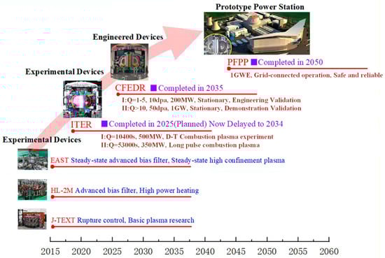
Figure 1.
The phased development roadmap for magnetic confinement fusion energy in China. This roadmap illustrates China’s strategic progression from experimental devices to the CFEDR and the conceptual prototype fusion power plant (PFFP), highlighting CFEDR’s pivotal role in bridging the gap to commercial energy. The direction of the arrow indicates the planned path for the development of the fusion device of China.
2.1. HT-7
Originating from the Soviet T-7 device acquired in 1991, the Institute of Plasma Physics, Chinese Academy of Sciences (ASIPP) upgraded and commissioned its first superconducting tokamak (HT-7) in 1994, establishing China as the fourth nation with such capability [13]. Equipped with 24 superconducting toroidal field coils, HT-7 pioneered critical milestones in magnetic confinement fusion. It achieved China’s first 10 s plasma discharge in 2000, set a world record of 63.95 s for high-temperature plasma in 2003, and later sustained a 400 s pulse in 2008, accumulating 118,000 discharges over 20 campaigns [14]. The project yielded significant technological advances across several domains. It progressed the field of superconducting cryogenics. It also developed novel RF wall conditioning techniques for impurity reduction and implemented plasma control systems with millisecond-scale response times [15,16]. At the same time, foundational research on plasma turbulence, pedestal physics, and divertor heat management directly informed EAST’s design and contributed to ITER’s steady-state operational strategies. HT-7’s legacy solidified China’s fusion research standing through both engineering breakthroughs and talent development [17,18].
2.2. EAST
EAST, the world’s first fully superconducting tokamak with a non-circular cross-section, was completed by ASIPP in 2006 [19]. Its design prioritized flexibility and ITER physics compatibility, achieving breakthroughs in superconducting magnets (<4 K/3.5 T), cryogenics, and high-power supplies [20]. Experimentally, EAST evolved through three phases: validating long-pulse capabilities (400 s discharges by 2011) [21], setting global milestones like 101.2 s H-mode plasma at 120 million °C (2017) [22], and advancing reactor-relevant operations, including 403 s steady-state H-mode (2023) [23] and a landmark 1066 s plasma at 100 million °C [24]. EAST has achieved systematic advancements in high-parameter operation, such as 1 MA plasma and over 30 MW of heating. These efforts have resulted in more than 15 world records. These achievements are foundational to China’s fusion roadmap. Concurrently, they accelerate the development of DEMO (Demonstration Power Plant)-relevant engineering on a global scale [10].
2.3. ITER
ITER, the world’s largest nuclear fusion project with 35 participating nations (including China, EU, India, Japan, Korea, Russia, and the USA) [25], aims to prove the engineering feasibility of commercial fusion energy using a tokamak design. Designed to achieve a burning plasma state using deuterium-tritium fuel, it targets a 500 MW fusion power output with energy gain (Q ≥ 10) for 400+ s [26], demonstrating self-sustaining fusion and paving the way for future power plants. Key milestones include the full assembly of the world’s largest cryostat, advanced Nb3Sn superconducting magnets, and a divertor capable of enduring >10 MW/m2 heat flux [6]. Though delayed by technical complexity and global disruptions (first plasma now ~2034, full D-T operation 2035–2039), over 85% of major components are delivered. Its breakthroughs in remote maintenance, plasma control, and materials establish ITER as the critical engineering benchmark for global demonstration reactors [27].
2.4. CFEDR
As China’s critical bridge between ITER and commercial fusion plants, the CFEDR, former name, China Fusion Engineering Test Reactor (CFETR), was conceived in 2011 to demonstrate steady-state operation, tritium self-sufficiency, and remote maintenance capabilities. Its design evolved from an initial compact configuration to a baseline 7.2 m major-radius tokamak with 6.5 T toroidal field and 14 MA plasma current, featuring Nb3Sn/NbTi superconducting magnets using graded CICC technology and a dual-divertor vacuum vessel compatible with helium-/water-cooled blankets (withstanding 20 MW/m2 heat flux) [28]. Physics simulations established feasible 1 GW hybrid scenarios (H98y2 = 1.14) and steady-state operations with reversed magnetic shear (βN = 2.97) [29], while divertor modeling confirmed heat flux control below 3 MW/m2 via impurity seeding [28]. Technologically, CFEDR advanced superconducting magnet prototypes (CS model coil, 2020) [30] validated vacuum vessel manufacturing techniques through 1/8 sector mockups, and progressed blanket thermal optimization. Its integrated engineering design underpins China’s “EAST → CFEDR → DEMO” roadmap, accelerating fusion commercialization by resolving reactor-scale engineering challenges [31].
3. Fusion Superconducting Magnet System
The confinement performance is predominantly determined by the magnetic field strength—higher field intensities significantly enhance plasma stability and prolong confinement duration, thereby increasing the probability of sustained fusion reactions [32,33]. A tokamak’s magnetic configuration relies on four fundamental coil systems: toroidal field (TF) coils, poloidal field (PF) coils, central solenoid (CS) coils, and correction coils (CCs). The TF coils generate a strong, doughnut-shaped magnetic field that confines the plasma particles along helical paths, preventing them from escaping [34]. The PF coils produce a vertical magnetic field that controls the plasma’s shape, position, and stability, ensuring optimal confinement [35]. The CS coils induce the plasma current through electromagnetic induction, helping initiate and sustain the fusion reaction. Finally, CC fine-tunes the magnetic field to compensate for imperfections and suppress instabilities, enhancing overall plasma control [34]. Together, these coils enable stable, long-term plasma confinement essential for nuclear fusion.
3.1. HT-7
The HT-7 magnet system integrates the TF system using 24 superconducting coils (see Table 1 for TF coil specifications) and the PF system with copper conductors, collectively enabling plasma confinement and control [36]. The PF system, comprising three symmetrically arranged central solenoid pairs and four poloidal coil pairs about the mid-plane, delivers a 10 V·s flux swing capable of inducing and sustaining 1 MA plasma currents for 10 s without auxiliary drive [37]. The integrated cryogenic system employs supercritical two-phase helium cooling powered by dual 500 W/4.5 K refrigerators. During the Tokamak engineering test phase in 1995, the cryogenic system supported the operation of the magnets under a toroidal magnetic field of 1.2–1.5 T for one month. After resolving the helium leakage issue in the cryostat, the device could operate stably under a toroidal magnetic field of 1.6–2.0 T.

Table 1.
Key parameters of the HT-7 Toroidal Field (TF) coil system. As China’s first superconducting tokamak, these NbTi-based magnets provided foundational engineering experience for subsequent devices.
3.2. EAST
EAST magnet system adopts a D-shaped cross-section design, incorporating 16 TF coils and 12 PF coils. TF coils employ NbTi strands and utilize the CICC structure to achieve high current density transmission. The main parameters of the EAST magnet system are listed in Table 2. The PF magnet system of EAST includes six sets of central solenoid coils, four sets of large coils, and four sets of divertor coils. The PF coils are also made of NbTi strands and used for plasma shaping, heating, and equilibrium. The poloidal field can provide a magnetic flux change of approximately 10 volt-seconds, generating and controlling a plasma current of 1~1.5 MA. The coils’ conductors are designed for a maximum operating current of 14.5 kA and a maximum field strength of Bp, max < 4.5 T [38].
Table 2.
Comparative engineering parameters of the EAST magnet system. It provides a side-by-side comparison of the key specifications for the Toroidal Field (TF), Central Solenoid (CS), and Poloidal Field (PF) coils, which constitute the world’s first fully superconducting tokamak magnet system.
3.3. ITER
The ITER magnet system, representing the world’s largest and most complex superconducting infrastructure, leverages 10,000 tonnes of Nb3Sn and NbTi CICCs, collectively storing 51 GJ of magnetic energy to initiate, confine, and dynamically stabilize fusion plasmas. The TF system employs 18 D-shaped Nb3Sn coils (each spanning 9 m × 17 m and weighing 330–360 tonnes) arranged concentrically around the vacuum vessel, generating a peak field of 11.8 T while storing 41 GJ to establish the primary confinement field. Complementing this, the CS, comprising six vertically stacked Nb3Sn modules reaching 18 m height and 1000 tonnes mass, achieves fields > 13 T and stores 6.4 GJ to inductively drive plasma currents up to 15 MA for 500 s, enabling sustained burn conditions. For precision plasma shaping, 6 PF coils (utilizing NbTi, 15–24 m diameter) deliver up to 6 T fields with 4 GJ stored energy, while 18 CCs actively compensate magnetic field errors (±0.1 mT tolerance) induced by manufacturing deviations across the 28,000 m3 cryostat volume. The main parameters of the magnet system are summarized in Table 3 [39].
Table 3.
The main parameters of the ITER magnet system.
3.4. CFEDR
The magnet system of CFEDR [40] consists mainly of 16 TF coils, 8 CS modules, 6 PF coils, and 18 CCs. The TF system consists of 16 D-shaped coils arranged around a plasma with a 7.2 m major radius. These coils operate at a maximum conductor current of 84.6 kA, generating 6.5 T at the plasma axis and peaking at 14.5 T in the inboard leg—significantly exceeding ITER TF parameters with its higher turn current and total stored energy (116.34 GJ vs. ITER’s 40.1 GJ). The design employs cost-optimized, rectangular cross-section Nb3Sn CICC with graded specifications across the TF coils. As shown in Figure 2, structural analysis reveals critical operational stresses: each coil experiences ~570 MPa centripetal forces in the inner leg, inducing maximum deformations of 14 mm. To withstand these extreme loads, the coil case incorporates a nearly 0.5 m thick structural reinforcement.
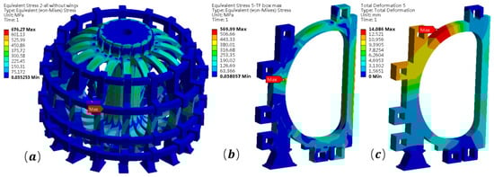
Figure 2.
Finite Element Analysis (FEA) of the CFEDR TF coil system, highlighting the associated mechanical engineering challenges. (a) The von Mises stress distribution across the entire TF assembly, (b) Stress concentration in a single coil case (peaking at ~570 MPa), (c) The total deformation (max. ~14 mm) under extreme electromagnetic (EM) loads.
To support the hybrid operation mode, the CS system is designed as an assembly of eight independently powered modules capable of delivering 400 V·s magnetic flux at a ramp rate of ~1.2 T/s for plasma current initiation and shaping. Each 2.25 m radius module features a 720-turn (18 × 40) winding configuration utilizing a hybrid superconducting approach—HTS for high-field regions and Nb3Sn LTS elsewhere—achieving a 19.9 T peak field at 51.25 kA/turn, with all coils maintained at 4.5 K by supercritical helium cooling.
4. Technology Development of Fusion Magnet
4.1. CICC
CICC solves extreme fusion magnet challenges, including electromagnetic stresses, thermal cycles, radiation, and field stability, by bundling superconducting strands in leak-tight jackets cooled by forced-flow supercritical helium. This architecture enables structural reinforcement, strain tolerance, and thermal stability. Figure 3 shows the cross section of CICC conductor used in different systems in different countries.
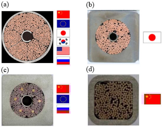
Figure 3.
CICC cross-section of each country. (a) PF conductor, Nb3Sn, conductor size: φ43.7 mm, the jackets’ thickness: 1.9 mm; (b) CS conductor, Nb3Sn, conductor size: 49 mm × 49 mm, inside diameter: φ32.6 mm; (c) PF conductor, NbTi, conductor size: 51.9 mm × 51.9 mm, inside diameter: φ35.3 mm; (d) CC conductor, NbTi, conductor size: 19.2 mm × 19.2 mm, the jackets’ thickness: 2.2 mm.
In ITER, NbTi-based CICCs power PF and CCs, operating at 4.2 K under ≤8 T fields with critical current density Jc ≥ 2900 A/mm2 (5 T) [41]. Their design features multistage twisted filaments (~20 mm pitch) in a copper matrix (Cu/non-Cu ≈ 1.6:1), jacketed in stainless steel. Helium flows through central spirals and inter-filament void fraction (33.5%) for cooling/stability. For ITER’s TF (12 T, 68 kA) and CS (13 T, 46 kA) coils, Nb3Sn CICCs achieve Jc ≈ 750 A/mm2 (12 T) using internal-tin/bronze-route strands reacted at 650–690 °C [42].
New-generation CICCs targeting DEMO/CFEDR demands (14.5 T, 95.6 kA at 4.2 K) employ high Jc Nb3Sn strands with Jc > 2000 A/mm2 at 12 T, 4.2 K [43]. These pack 864 superconducting/copper strands in 316LN jackets (~49 mm OD) with short twist pitches to minimize AC losses and peak strand strain [44]. Central helically wound cooling spirals (8 mm) and around 32.5% void space enable a uniform helium flow.
In a tokamak’s pulsed operational regime, the CICC is subjected to rapidly time-varying magnetic fields (dB/dt), which induce significant AC losses [45]. These losses, originating from both the hysteresis of superconducting filaments and inter-strand coupling eddy currents, translate directly into a pulsed thermal load imposed upon the 4.5 K cryogenic cooling system [46]. Consequently, CICC structural design confronts a fundamental physical trade-off: the need to strike an engineering compromise between minimizing AC losses (short twist pitches) and mitigating mechanical stress (long twist pitches) [44,47,48]. This conundrum represents a central challenge that projects such as CFEDT are actively addressing through R&D on advanced cabling patterns.
Strand deformation constitutes the quintessential mechano–electro–thermo-coupled challenge within CICC technology [49]. This deformation is precipitated by a confluence of factors: initial stress from manufacturing compaction, thermal cycling strains originating from the thermal expansion coefficient mismatch, and the cumulative impact of immense, cyclic Lorentz forces during operation. China’s initiative to re-engineer the cable pattern at its manufacturing root—exemplified by the CWS (Copper Wound Superconducting strand) design from ASIPP, is strategically intended to mitigate strand pinching during fabrication and cyclic loading, thereby concurrently bolstering both the mechanical and thermo-hydraulic stability of the CICC [50,51].
The primary design objective for the ITER CICC was to validate the industrial capacity for large-scale manufacturing, winding, and integration of a GJ-scale Nb3Sn magnet system. Consequently, its parameters are relatively conservative, prioritizing industrial feasibility and operational reliability. In contrast, the CFEDR CICC design is explicitly performance-driven, targeting the higher magnetic fields and greater fusion power density required for the DEMO stage. Achieving this objective within the constrained winding pack necessitates the use of strands with a higher critical current, an increased number of strands, and a significantly higher operational current.
HTS provides significant opportunities for advancing fusion science towards fusion energy production [52,53]. Compared to LTS, it enables more compact fusion machines with magnetic fields exceeding 20 T [54]. Among practical HTS materials, Bi2212 wires and REBCO (Rare-earth barium-copper-oxide) tapes are promising candidates. To find a solution for the large-scale, high-current magnets application, their cable-in-conduit conductor technologies are very critical [55].
The choice between LTSs (Nb3Sn) and HTSs (REBCO/Bi2212) represents a central point of divergence in the design of fusion magnets. Nb3Sn is a mature industrial material, and its CICC technology has been fully verified, but its performance will decline rapidly above 4.2 K and 15 T [56]. In contrast, a HTS (especially REBCO) has a higher upper critical field and temperature margin, which makes it possible to operate under a magnetic field of >20 T or at a higher temperature (~20 K), thus achieving a more compact fusion reactor design [52,57]. However, the main challenges of a HTS are its inherent anisotropy, the high cost of materials, and the process complexity of making fragile strips or wires into strong, uniform high-current CICC wires.
4.2. Superconducting Coil
Superconducting fusion coil technology has progressed from NbTi systems (e.g., EAST’s 3.5 T coils) to high-field Nb3Sn architectures pioneered by ITER. This evolution culminates in the CFEDR central solenoid model coil (CSMC) [58], which is designed to validate the engineering maturity of the ITER-derived conductor technology for the next generation of reactors.
The Comprehensive Research Facility for Fusion Technology (CRAFT) project, started in 2019 to develop key engineering technologies for CFEDR, features the full-scale CFEDR TF prototype coil as a key component. This coil enables the development and qualification of critical technologies: high-performance superconducting strands, CICC, coil winding, and manufacturing processes. Its winding pack is partitioned into high-field, middle-field, and low-field zones based on magnetic field distribution, achieving peak fields up to 14.5 T [30]. See Figure 4 for the winding structure and Table 4 for technical specifications [59].
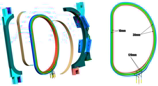
Figure 4.
Graded winding pack design for the CFEDR TF prototype coil. This design optimizes conductor usage by partitioning the winding into High Field (HF, red), Medium Field (MF, green), and Low Field (LF, blue) zones—which correspond to the parameters in Table 4—to manage the 14.4 T peak magnetic field.
Table 4.
The international partial fusion device magnet index. The magnetic field, size and information of superconducting materials used in TF coils of each device are compared.
To achieve the fields (~20 T) required for next-generation fusion reactors like CFEDR, LTS faces fundamental limitations in critical current performance under high fields [60]. This necessitates developing HTS coil technology, which offers superior critical field limits and higher temperature operation to enable compact, high-field fusion systems [61]. While current HTS applications primarily utilize small-scale or densely wound magnets, large-scale, high-current HTS coil technology capable of meeting fusion requirements remains in active development.
4.3. Superconducting Joint
Superconducting joints are essential for minimizing energy loss and ensuring lifecycle reliability in fusion magnets. Operating at 4–10 K, they must maintain ultra-low electrical resistance (<1 nΩ) and high mechanical strength (>50 MPa) while enduring extreme electromagnetic loads, neutron irradiation, and thermal cycles [62]. Joint performance directly dictates magnet efficiency, thermal stability, and reactor feasibility, driving global efforts to overcome material and manufacturing limitations.
For LTS Nb3Sn magnets, joint evolution resolves heat treatment–integrity conflicts. ITER’s diffusion-welded joints achieved 5 nΩ but degraded cyclically. DEMO’s solution employs layer-to-layer graded joints: sandblasted Nb3Sn cables are copper-coated (3 mm via arc spray) and diffusion-bonded (650 °C/30 MPa). China’s CFEDR further innovated with a “spliced” internal joint design—copper-solder-filled conductors encapsulated in steel jackets [31,63].
HTS joints for CORC (Conductor on Round Core) cables (carrying >10 kA/cm) address REBCO tape anisotropy and neutron resilience. Geometric optimization is key: MIT’s mechanically clamped joints achieved 3 × 10⁻⁹ Ω but suffered irradiation embrittlement, while Mulder’s staircase trimming design reduced resistance by 70% via direct layer-by-layer current injection. ASIPP enhanced precision with laser positioning (±0.2 mm deviation control). Soldering breakthroughs include Liu’s vacuum Sn-Ag-Cu infiltration (8.65 nΩ per tape interface, <5% Ic degradation) [64] and Yang’s HTS bridge joint (3.5 × 10⁻⁹ Ω at 100 mm length) [65]. DEMO’s radiation-hardened insulation (SiC/PEEK-ceramic-silicone) limited dielectric loss to 12% at 5 × 10²² n/m2, and CORC’s Cu-Ni sheath shielded 80% of neutron damage, restricting Jc degradation to <5% [31].
4.4. Magnet Quench Detection and Protection System
The reliability of fusion superconducting magnets critically depends on quench management, where real-time temperature diagnostics are essential for early quench identification [66]. Deployed near conductors, these detect micro-Kelvin fluctuations and thermal gradients, enabling rapid intervention. Post-quench validation via thermal simulation (against ITER’s < 150 K hot-spot limit) further optimizes protection systems [67]. However, REBCO HTS magnets introduce acute challenges: extreme electromagnetic noise (plasma disruptions, eddy currents) obscures voltage signals, while their intrinsically slow normal-zone propagation velocity (~1 cm/s, one-tenth of Nb3Sn LTS) requires millisecond-level detection responses. Critically, this slow propagation, combined with GJ-scale stored energy, exacerbates local hot-spot burnout risks, demanding systemic innovations in multimodal sensing [68,69]. These characteristics compel research toward innovations in multimodal sensing and systemic protection strategies.
To overcome traditional voltage monitoring limitations, especially for CICC subject to strong electromagnetic interference, integrated approaches now deploy embedded fiber optic sensors for distributed thermometry, current-distribution reconstruction algorithms for early anomaly detection, 100 kA conductors to reduce operating voltage, and engineered resistive turns for localized heat dissipation [70,71,72,73,74]. China’s fusion program exemplifies the paradigm shift from passive monitoring to active protection, demonstrating engineering feasibility in fiber-based diagnostics and current mapping; however, nuclear-grade certification under irradiation and real-time integration of multi-sensor systems remain critical bottlenecks for full-scale reactor deployment.
4.5. Cryogenic Technology and Heat Management
Superconducting fusion magnets necessitate stable operation at liquid helium temperatures (4.5 K), where thermal load management becomes critical due to multi-source heat intrusion. Systems like CFEDR’s TF coils, storing 122 GJ of energy, face conductive heat leakage through structural supports, radiative heat from warm surfaces (>300 K), and AC losses during operation. Unmitigated heat ingress risks quench events and system failure. Effective thermal management through multi-stage zoning (e.g., EAST’s 300 K → 70 K → 4.5 K gradient layers) intercepts >90% of parasitic heat before reaching superconducting coils, enabling magnet stability [75]. This thermal-structural compromise constitutes a fundamental engineering challenge for fusion energy systems.
Cryogenic technology and thermal load management for fusion magnets face multifaceted engineering challenges. The primary challenges include:
- Maintaining and controlling an extremely low-temperature environment (e.g., 4.2 K) within large-scale, complex magnet structures.
- Minimizing heat intrusion from multiple sources (conduction, radiation, AC losses, etc.) through optimized structural design and material selection.
- Effective design and implementation of thermal interception measures such as thermal anchors, with validation via precise numerical simulations.
- Development and application of accurate coupled thermal-electromagnetic-mechanical analysis models to predict temperature distributions and structural responses under complex loads.
- Reliable temperature monitoring during magnet operation, particularly during transient events (e.g., quench) to enable precise thermal gradient identification for timely protection.
- Accounting for cryogenic material property variations in structural design and analysis.
Overcoming these challenges is critical for achieving long-term stable and safe operation of large-scale fusion magnets, directly determining the success of future fusion energy development.
4.6. Engineering Validation and Technology Qualification
Converting the design blueprint of fusion magnets into a reliable engineering entity relies on a multi-level, high-standard verification process. Experimental testing of key components is the cornerstone of reducing equipment risk.
The critical CICC design must be verified in facilities such as SULTAN (cable testing laboratory in Switzerland). ITER’s NbTi-based CICCs support 40–60 kA currents with ≤10% Ic degradation during cycling, and Nb3Sn CICCs achieve Jc ≈ 750 A/mm2 (12 T) [42]. For the next generation of high Jc Nb3Sn CICC required by CFEDR, short-sample tests demonstrate Ic (14.5 T) ≈ 95.6 kA with ≤10% degradation after 1000 electromagnetic cycles and Warm-Up/Cool-Down tests, with peak strand strain < −0.5% [44].
A series of insert coils [76,77] have been manufactured with REBCO CICC cable for investigation of the current carrying stability under conditions such as cyclic high electromagnetic and thermal loads, as well as quenching with a voltage reached about 15 times the criterion. In 2024, a full-size CICC specimen with an operation current of 80 kA under a 4.5 K and 10.85 T background magnetic field condition have been tested at the SULTAN lab, which shows stable operation characteristics under a maximum electromagnetic load of around 830 kN/m, warm up and cool down between RT and 4.5 K and so on [52], which plays an important role in HTS CICC technology development and performance verification. In the same year, ASIPP succeeded in producing a CICC type Bi-2212 insert coil, the coil exhibited excellent current-carry capacity and stability with electromagnetic loads or quench events [78].
The most important verification step comes from the large model coil. The CSMC is a milestone achievement. It did not only demonstrate record Nb3Sn performance at 12 T/47.65 kA with 407.6 MJ stored energy, but also validated a complete set of industrial processes from wire cable formation, coil winding, insulation treatment, joint fabrication to low-temperature cooling and quench protection [58]. This achievement signifies readiness to scale LTS-based solutions for the next-generation fusion reactor.
Despite the success of CSMC’s testing, these validations do not fully address the challenges of industrial scale adoption. Key outstanding issues include ensuring high-performance uniformity of HTS tapes in kilometer-scale lengths and large coil windings. In addition, the reliability of the quench detection system under real, long-pulse DEMO conditions (high noise, strong radiation) has not been fully verified. Successfully verifying a reliable and fast-responding protection scheme for a GJ-level HTS magnet is still a key verification gap.
5. International Benchmarking and Lessons Learned
The development of magnet technology in China is carried out in the context of the rapid evolution of global fusion technology. The technical indexes of Chinese and international fusion magnets are compared in general. Table 4 compares the magnetic field, size, and superconducting material information of the TF coils of each device.
As the world ‘s first fully superconducting tokamak, China EAST has a magnetic field strength of 3.5–4.0 T in the center of the toroidal field, and a large radius of 1.85 m [79]. The NbTi/Nb3Sn LTS material has been used to realize the operation of kilo-second long-pulse high-confinement plasma and second-level long-pulse high-confinement plasma [80], laying an experimental foundation for the engineering fusion reactor. China CFEDR is a technical interface device between ITER and DEMO. The CFEDR is designed to be a hybrid magnet system with Nb3Sn as the main part and HTS as the auxiliary part. The designed toroidal field strength is 6.5 T and the large radius is extended to 7.2 m [40,81].
Internationally, JT-60SA is the largest and most advanced superconducting tokamak in Japan except ITER [82]. The successful operation of its magnet system (all using LTS) provides a key benchmark for the design, manufacture and integration of large Nb3Sn and NbTi CICC. By undertaking procurement tasks such as ITER PF coils and the development of CFEDR CSMC [83,84], China has demonstrated the ability to manufacture high-performance LTS CICC on an industrial scale, and has reached the same level as JT-60 SA in terms of Nb3Sn wire performance and large coil winding process [84]. This indicates that China has mastered the core industrial technology for the construction of DEMO-level LTS magnets.
The SPARC project, jointly developed by Commonwealth Fusion Systems (CFS) and MIT in the United States, represents a “high field compact” route that is very different from ITER and CFEDR. SPARC relies on REBCO HTS magnet to achieve ultra-high magnetic field (~20 T), so as to achieve Q > 10 with smaller size and lower cost [85,86,87,88,89]. This brings strategic considerations to China’s “CFEDR → DEMO” roadmap based on LTS. As described in Section 4.1, China is also actively exploring HTS CICC (such as ASIPP’s HFRC (High Flexible REBCO Cables) and Bi2212 wire development) [77,90,91,92], but the success of SPARC (if realized) will prove the disruptive potential of HTS tapes solutions. China’s HTS research and development currently focuses more on providing hybrid solutions for CFEDR high-field areas (such as CS), or providing technical reserves for more remote compact power stations (such as HH70 with energy singularity [93,94]), which is different from SPARC’s full HTS path.
The CFEDR and EU DEMO are highly consistent in their design objectives: steady-state operation, T-generation self-sustaining, and fusion power of >1 GW [95,96]. Therefore, the magnet challenges faced by the two are also highly comparable. Both CFEDR magnets (14.5 T, 122 GJ energy storage [84]) and EU DEMO (~13 T, >100 GJ energy storage [95]) face severe structural design and quench protection challenges brought by GJ-level energy storage and huge electromagnetic force (up to hundreds of MPa) [84,97]. Lessons learned by CFEDR in the development of CSMC and TF prototype coils, for example, verified the performance of Nb3Sn CICC under high stress, tested the stable operation of large-scale cryogenic systems, and developed a multi-channel quench detection system [98,99]. These experiences are not only the success of CFEDR itself but also provide valuable engineering data and “de-risk” verification for EU DEMO and even global DEMO design. These R&D activities prove that China has the ability to solve the problem of DEMO-level system integration.
6. Engineering Challenges
China has made remarkable progress in fusion magnet technology, but there are still several major and unresolved engineering challenges that need to be overcome in order to achieve the goal of CFEDR and eventually move towards commercial fusion reactors (PFFPs).
6.1. Radiation Resistance
Once the fusion reactor is operated, the neutron irradiation that cannot be avoided at present will cause damage to the magnet system. Nb3Sn strands are highly sensitive to neutron irradiation; high-energy neutrons produce lattice disorder that markedly reduces both the critical temperature (Tc) and the critical current density (Jc) of the material [100]. Experimental studies on ITER-type bronze-route Nb3Sn wires show that moderate neutron fluences ≈ 5 × 10²² n m−2) can initially increase Jc by creating additional flux-pinning centers, but higher fluences (≥1 × 10²³ n m−2) lead to a monotonic degradation of Tc, Bc and Jc, confirming the strong sensitivity of Nb3Sn to radiation damage [101,102,103].
In contrast, HTSs based on REBCO exhibit considerably better radiation tolerance [104]. Gamma-ray and neutron irradiation up to several MGy (or neutron fluences of ≈8 × 10²¹ n m−2) cause only modest reductions in Tc and Jc, and in some cases an initial increase in Jc due to irradiation-induced pinning. Fast-neutron studies on REBCO coated conductors (with and without artificial pinning centers) reveal that Jc can even be enhanced at low fluences, while degradation appears only at much higher fluences than those that damage Nb3Sn [105]. Moreover, recent D-T fusion-neutron experiments on YBCO films and commercial REBCO tapes showed no significant change in superconducting properties up to a fluence of 1.2 × 1014 cm−2, indicating a robust performance of REBCO under fusion-relevant neutron spectra [106].
Nb3Sn strands are highly sensitive to neutron irradiation. High-energy neutrons can cause lattice damage and significantly reduce the critical temperature and critical current density. Although the HTS (especially REBCO) exhibits better radiation resistance, its long-term performance evolution still needs to be fully verified.
6.2. HTS Manufacturability and Cost
As described in Section 4.1, HTS (REBCO and Bi2212) is the hope to achieve a high field above 15 T. However, it faces great obstacles to push it from laboratory samples to industrial applications. The production cost of REBCO tapes is still high, and it is challenging to maintain uniform high performance on a scale of thousands of kilometers [53,107]. In addition, the process complexity, bending strain control and joint technology of converting fragile HTS tapes into CICC wires (such as CORC or HFRC structures) capable of carrying tens of kA currents without damage are still global challenges that have not yet been fully overcome [52].
6.3. Insulation Degradation Under Coupled Fields
The magnet insulation system works in an extreme multi-field coupling environment: deep low temperature, strong neutron irradiation, high mechanical stress and high electric field. The synergistic effect of these factors will accelerate the aging and degradation of insulation. At present, we know little about the long-term performance evolution of materials in such a complex coupling environment, which brings great uncertainty to the reliability and safety of reactors [108,109,110].
7. Conclusions
In the past three decades, China has achieved leapfrog development in the field of fusion magnet technology through the robust strategic path of “HT-7 → EAST → CFEDR”. China’s fusion magnet technology has gone from “following” to “running side by side” and has the potential to “lead” in some areas. Its core achievement is that an independent, complete and large-scale fusion magnet industrial system has been established around the superconducting tokamak route, covering the whole chain of advanced superconducting strands, CICC wires, large coil manufacturing, cryogenic testing and system integration. The global impact of this achievement is equally profound. China has contributed valuable engineering data to the international fusion community through the development of high-standard delivery of ITER procurement packages and model coils. In particular, the stable operation verification of Nb3Sn CICC wire under high-stress conditions provides key ‘de-risk’ support for the design of global DEMO reactors. The global impact of this achievement is equally profound. China has contributed valuable engineering data to the international fusion community by delivering ITER procurement packages to high standards. In particular, the stable operation verification of Nb3Sn CICC wire under high stress conditions provides the key “de-risk” support for the design of global DEMO reactors.mo.
Looking forward to the next 5–10 years, the key technical milestones are expected to be the breakthrough in industrial scale production and cost control of HTS conductors (especially REBCO), as well as the final engineering verification of CFEDR key prototype systems, laying the foundation for steady-state operation and T-product self-sustainment. It must be emphasized that the realization of these goals is inseparable from the support of advanced cryogenic technology. The application of GJ-level magnet energy storage, tens of thousands of amperes of CICC wires and HTS has put forward unprecedented requirements for the scale, thermal hydraulic stability and thermal management efficiency of cryogenic systems. Therefore, innovation in large cryogenic loops, high-efficiency heat shields, and new refrigerators will be the key enabling technologies that determine whether future fusion reactors can achieve high availability.
In the end, China’s fusion strategy still faces a path choice whether to continue to optimize the mature LTS industrial system, or to turn to the high-risk and high-return compact route brought by HTS. No matter which path is selected, the core engineering bottlenecks (such as material irradiation resistance, insulation degradation and quench protection, etc.) identified by this analysis must be overcome. With its accumulated deep engineering foundation, China is in a favorable position to solve these key scientific and engineering problems in the future, thus playing a more critical leading role in the development of global fusion energy.
Author Contributions
Conceptualization, H.L. and F.L.; methodology, W.H.; validation, H.L.; investigation, S.G.; resources, H.L. and F.L.; data curation, W.H.; writing—original draft preparation, W.H. and S.G.; writing—review and editing, S.G. and F.L.; supervision, H.L.; project administration, F.L.; funding acquisition, H.L. All authors have read and agreed to the published version of the manuscript.
Funding
This research was funded by the Comprehensive Research Facility for Fusion Technology Program of China, grant No. 2018-000052-73-01-001228.
Data Availability Statement
No new data were generated in this study. The data used are from previously published sources, as cited in the article.
Conflicts of Interest
The authors declare no conflict of interest.
References
- Vogel, M. Fusion: An introduction to the physics and technology of magnetic confinement fusion, 2nd edn., by W.M. stacey: Scope: Textbook. Level: Advanced undergraduate students. Contemp. Phys. 2011, 52, 595–596. [Google Scholar] [CrossRef]
- Ongena, J.; Koch, R.; Wolf, R.; Zohm, H. Magnetic-confinement fusion. Nat. Phys. 2016, 12, 398–410. [Google Scholar] [CrossRef]
- Huang, C.; Li, L. Magnetic confinement fusion: A brief review. Front. Energy 2018, 12, 305–313. [Google Scholar] [CrossRef]
- Helander, P. Theory of plasma confinement in non-axisymmetric magnetic fields. Rep. Prog. Phys. 2014, 77, 087001. [Google Scholar] [CrossRef]
- Artsimovich, L.A. Tokamak devices. Nucl. Fusion 1972, 12, 215. [Google Scholar] [CrossRef]
- ITER—The Way to New Energy. Available online: https://www.iter.org/node (accessed on 20 June 2025).
- Song, Y. The progress and current status of tokamak: A systematic review. E3S Web Conf. 2021, 292, 02067. [Google Scholar] [CrossRef]
- Murph, S.E.H.; Murph, M.A. Nuclear fusion: The promise of endless energy. Phys. Sci. Rev. 2023, 8, 3095–3118. [Google Scholar] [CrossRef]
- Huang, J.; Gong, X.; Garofalo, A.M.; Qian, J.; Ding, R.; Zhang, X.J.; Chen, J.L.; Li, M.H.; Yu, Y.W.; Wang, Y.F.; et al. Long-pulse high-performance H-mode plasmas achieved on EAST. Phys. Plasmas 2023, 30, 062504. [Google Scholar] [CrossRef]
- Li, J.; Ni, M.; Lu, Y. The frontier and perspective for tokamak development. Natl. Sci. Rev. 2019, 6, 382–383. [Google Scholar] [CrossRef]
- Gao, X.; Wan, B.; Song, Y.; Li, J.; Wan, Y. Progress on CFETR physics and engineering. Sci. Sin. Phys. Mech. Astron. 2018, 49, 045202. [Google Scholar] [CrossRef]
- Mohamed, M.; Zakuan, N.D.; Tengku Hassan, T.N.A.; Lock, S.S.M.; Mohd Shariff, A. Global development and readiness of nuclear fusion technology as the alternative source for clean energy supply. Sustainability 2024, 16, 4089. [Google Scholar] [CrossRef]
- Jie, Y.X.; Gao, X.; Cheng, Y.F.; Yang, K.; Tong, X.D. Multi-channel FIR HCN laser interferometer on HT-7 tokamak. Int. J. Infrared Millim. Waves 2000, 21, 1375–1380. [Google Scholar] [CrossRef]
- Baonian Wanfor the EAST and HT-7 Teams; International Collaborators. Recent experiments in the EAST and HT-7 superconducting tokamaks. Nucl. Fusion 2009, 49, 104011. [CrossRef]
- Yang, X.K.; Zhao, Y.P.; Li, J.G.; Li, C.F.; Shao, Y.G.; Mao, Y.Z.; Gu, X.M.; Xu, D.Z.; Ding, J.Y.; Xue, D.Y.; et al. Recent ICRF experiments on HT-7 superconducting tokamak. AIP Conf. Proc. 1999, 485, 156–159. [Google Scholar] [CrossRef]
- Peijie, W.; Jiarong, L.; Hua, W.; Guiming, L. Alternate data acquisition and real-time monitoring system on HT-7 tokamak. Plasma Sci. Technol. 2005, 7, 3114. [Google Scholar] [CrossRef]
- Wang, T. Superconducting Magnet Technology and Magnetic Confinement Nuclear Fusion. South. Energy Constr. 2022, 9, 108–117. [Google Scholar] [CrossRef]
- Xu, P.; Hu, L.Q.; Lin, S.Y.; Duan, Y.M.; Zhang, J.Z.; Zhong, G.Q.; Lu, H.W.; Chen, K.Y. Soft x-ray PHA measurement of the long pulse discharge in HT-7 tokamak. Phys. Lett. A 2010, 374, 2452–2460. [Google Scholar] [CrossRef]
- Wei, J.; Chen, W.G.; Wu, W.Y.; Pan, Y.N.; Gao, D.M.; Wu, S.T.; Wu, Y. The Superconducting Magnets for EAST Tokamak. IEEE Trans. Appl. Supercond. 2010, 20, 556–559. [Google Scholar] [CrossRef]
- Ni, M. Magnetohydrodynamics relevant to liquid blanket of fusion. Mech. Eng. 2010, 32, 1–9. [Google Scholar]
- Gong, X.; Wan, B.; Li, J.; Qian, J.; Li, E.; Liu, F.; Zhao, Y.; Wang, M.; Xu, H.; Garofalo, A.M.; et al. Realization of minute-long steady-state H-mode discharges on EAST. Plasma Sci. Technol. 2017, 19, 032001. [Google Scholar] [CrossRef]
- China Makes Key Breakthrough in Artificial Sun Research—Xinhua|English.news.cn. Available online: http://www.xinhuanet.com//english/2017-07/05/c_136419583.htm (accessed on 7 November 2025).
- East. Available online: http://east.ipp.ac.cn/index/article/info/id/92.html (accessed on 7 November 2025).
- Zhang, X.; Qin, J. Mechanical effects: Challenges for high-field superconducting magnets. Natl. Sci. Rev. 2023, 10, nwac220. [Google Scholar] [CrossRef]
- Combescure, D.; Ayneto, J.; Rueda, F.; Maqueda, L.G.; Moya, L.; Olalde, J.; Domínguez, V.; Zhang, X.; Schioler, T.; Sannazzaro, G.; et al. Seismic analysis of the tokamak complex building of iter fusion facility. In Proceedings of the 24th Conference on Structural Mechanics in Reactor Technology, Busan, Republic of Korea, 20–25 August 2017. [Google Scholar]
- Van Dam, J.W. Progress towards burning plasmas. Plasma Fusion Res. 2009, 4, 035. [Google Scholar] [CrossRef]
- Hesch, K. Progress in particular fields of fusion technology presented at the 29th IAEA fusion energy conference 2023. Nucl. Fusion 2024, 64, 117002. [Google Scholar] [CrossRef]
- Cheng, X.; Liu, Z.; Liu, S.; Peng, C.; Wang, W.; Ling, Q. A water loop design for the CRAFT project towards the testing of CFETR water-cooled blanket and divertor. Energies 2021, 14, 7354. [Google Scholar] [CrossRef]
- Li, Z.-Y.; Chan, V.S.; Zhu, Y.-R.; Jian, X.; Chen, J.-L.; Cheng, S.-K.; Zhu, P.; Xu, X.-Q.; Xia, T.-Y.; Li, G.-Q.; et al. Ideal MHD stability and characteristics of edge localized modes on CFETR. Nucl. Fusion 2017, 58, 016018. [Google Scholar] [CrossRef]
- Dai, C.; Wu, Y.; Li, J.; Guo, Z.; Qin, J.; Long, F.; Nijhuis, A.; Bruzzone, P.; Stepanov, B.; Shi, Y.; et al. Performance test and analysis of the first large-scale cable-in-conduit conductor with high jc Nb3Sn strand for fusion reactor. Nucl. Fusion 2021, 61, 036044. [Google Scholar] [CrossRef]
- Zheng, J.; Qin, J.; Lu, K.; Xu, M.; Duan, X.; Xu, G.; Hu, J.; Gong, X.; Zang, Q.; Liu, Z.; et al. Recent progress in Chinese fusion research based on superconducting tokamak configuration. Innovation 2022, 3, 100269. [Google Scholar] [CrossRef]
- Holtkamp, N. An overview of the ITER project. Fusion Eng. Des. 2007, 82, 427–434. [Google Scholar] [CrossRef]
- Zhang, Y.; Tang, Y.; Xu, Y.; Xia, Z.; Ren, L. Numerical simulation of a no-insulation BSCCO toroidal magnet applied in magnetic confinement fusion. Sci. Technol. Nucl. Install. 2018, 2018, 2914036. [Google Scholar] [CrossRef]
- Winter, H.P. HCI issues in tokamak fusion plasmas. J. Phys. Conf. Ser. 2007, 58, 33. [Google Scholar] [CrossRef]
- Gaye, O.; Moulay, E.; Brémond, S.; Autrique, L.; Nouailletas, R.; Artaud, J.F.; Orlov, Y. Robust stabilization of the current profile in tokamak plasmas using sliding mode approach in infinite dimension. Control Eng. Pract. 2013, 21, 1350–1358. [Google Scholar] [CrossRef]
- Chen, W.-G.; Pan, Y.-N.; Wu, S.-T.; Weng, P.-D. FE stress analysis of the toroidal field magnets of HT-7U. Plasma Sci. Technol. 2000, 2, 127. [Google Scholar] [CrossRef]
- Wan, Y.X.; Weng, P.D.; Li, J.G.; Yu, Q.Q.; Gao, D.M.; Team, U. HT-7U Superconducting Tokamak: Physics Design, Engineering Progress and Schedule; HT-7U Team: Anhui, China, 2003. [Google Scholar]
- Wan, Y.X.; Weng, P.D.; Li, J.G.; Gao, D.M.; Wu, S.T. Progress of the EAST project in China. In Proceedings of the 21th International Atomic Energy Agency (IAEA) Fusion Energy Conference, Villamoura, Portugal, 1–6 November 2004. [Google Scholar]
- Mitchell, N.; Devred, A. The ITER magnet system: Configuration and construction status. Fusion Eng. Des. 2017, 123, 17–25. [Google Scholar] [CrossRef]
- Zhuang, G.; Li, G.Q.; Li, J.; Wan, Y.X.; Liu, Y.; Wang, X.L.; Song, Y.T.; Chan, V.; Yang, Q.W.; Wan, B.N.; et al. Progress of the CFETR design. Nucl. Fusion 2019, 59, 112010. [Google Scholar] [CrossRef]
- Krasilnikov, A.V.; Abdyuhanov, I.M.; Aleksandrov, E.V.; Alekseev, A.G.; Amosov, V.N.; Antonov, N.V.; Arkhipov, N.I.; Burdakov, A.V.; Chugunov, I.N.; Denisov, G.G.; et al. Progress with the ITER project activity in russia. Nucl. Fusion 2015, 55, 104007. [Google Scholar] [CrossRef]
- Sborchia, C.; Bonito Oliva, A.; Boutboul, T.; Chan, K.; Devred, A.; Egorov, S.; Kim, K.; Koizumi, N.; Lelekhov, S.; Libeyre, P.; et al. The ITER magnet systems: Progress on construction. Nucl. Fusion 2013, 54, 013006. [Google Scholar] [CrossRef]
- Muzzi, L.; Affinito, L.; Chiarelli, S.; Corato, V.; della Corte, A.; De Marzi, G.; Di Zenobio, A.; Zignani, C.F.; Freda, R.; Turtù, S.; et al. Design and characterization of the interlayer joint between low-field Nb3Sn conductors of a layer wound DEMO TF coil. IEEE Trans. Appl. Supercond. 2021, 31, 1–7. [Google Scholar] [CrossRef]
- Qin, J.; Dai, C.; Liu, B.; Wu, Y.; Liu, F.; Liao, G.; Xue, T.; Wei, Z.; Nijhuis, A.; Zhou, C.; et al. Optimization of CFETR CSMC cabling based on numerical modeling and experiments. Supercond. Sci. Technol. 2015, 28, 125008. [Google Scholar] [CrossRef]
- Lelekhov, S.A.; Keilin, V.E.; Kovalev, I.A.; Kruglov, S.L.; Shcherbakov, V.I.; Shutov, K.A. Eddy current loss in superconducting cable-in-conduit conductor (CICC). IEEE Trans. Appl. Supercond. 2012, 22, 4705704. [Google Scholar] [CrossRef]
- Martovetsky, N.; Minervini, J.; Okuno, K.; Salpiero, E.; Filatov, O. Current status and future technical challenges for tokamak magnets. Fusion Sci. Technol. 2003, 44, 19–26. [Google Scholar] [CrossRef][Green Version]
- Nijhuis, A.; van Lanen, E.P.A.; Rolando, G. Optimization of ITER Nb3Sn CICCs for coupling loss, transverse electromagnetic load and axial thermal contraction. Supercond. Sci. Technol. 2011, 25, 015007. [Google Scholar] [CrossRef]
- Di Zenobio, A.; Albanese, R.; Anemona, A.; Biancolini, M.E.; Bonifetto, R.; Brutti, C.; Corato, V.; Crisanti, F.; della Corte, A.; De Marzi, G.; et al. DTT device: Conceptual design of the superconducting magnet system. Fusion Eng. Des. 2017, 122, 299–312. [Google Scholar] [CrossRef]
- Yue, D.; Zhang, X.; Zhou, Y.; Yue, D.; Zhang, X.; Zhou, Y. The mechanical behavior of the cable-in-conduit conductor in the ITER project. In Nuclear Fusion—One Noble Goal and a Variety of Scientific and Technological Challenges; IntechOpen: London, UK, 2018; ISBN 978-1-78985-788-7. [Google Scholar]
- Liu, Y.; Wu, Y.; Nijhuis, A.; Guo, Z.; Shi, Y.; Liu, F.; Zhu, L.; Dai, C.; Shin, I.; Sim, K.; et al. Impact of local plastic deformation on thermo-magnetic instability of high-jc Nb3Sn strand. Supercond. Sci. Technol. 2024, 37, 045002. [Google Scholar] [CrossRef]
- Qin, J.; Wu, Y.; Li, J.; Liu, F.; Dai, C.; Shi, Y.; Liu, H.; Mao, Z.; Nijhuis, A.; Zhou, C.; et al. New design of cable-in-conduit conductor for application in future fusion reactors. Supercond. Sci. Technol. 2017, 30, 115012. [Google Scholar] [CrossRef]
- Jin, H.; Xiao, G.; Zhou, C.; Zhao, C.; Shi, S.; Liu, H.; Liu, F.; Liu, H.; Wu, Y.; Wu, Z.; et al. Performance of the first 80-kA HTS CICC for high-field application in future fusion reactors. Engineering 2025, 55, 182–190. [Google Scholar] [CrossRef]
- Bruzzone, P.; Fietz, W.H.; Minervini, J.V.; Novikov, M.; Yanagi, N.; Zhai, Y.; Zheng, J. High temperature superconductors for fusion magnets. Nucl. Fusion 2018, 58, 103001. [Google Scholar] [CrossRef]
- Uglietti, D. A review of commercial high temperature superconducting materials for large magnets: From wires and tapes to cables and conductors. Supercond. Sci. Technol. 2019, 32, 053001. [Google Scholar] [CrossRef]
- Xiao, G.Y.; Liu, F.; Jin, H.; Zhou, C.; Qin, J.G.; Liu, H.J.; Li, J.G.; Dai, T.L.; Zhang, X.T. Experimental study on cabling properties of different REBCO coated tapes. J. Phys. Conf. Ser. 2020, 1559, 012111. [Google Scholar] [CrossRef]
- Kwon, S.P.; Park, S.H.; Stepanov, B.; Bruzzone, P.; Kim, K. Preliminary performance test results of first CICC from korea destined for an ITER TF magnet. IEEE Trans. Appl. Supercond. 2013, 23, 4201705. [Google Scholar] [CrossRef]
- Zhai, Y.; van der Laan, D.; Connolly, P.; Kessel, C. Conceptual design of HTS magnets for fusion nuclear science facility. Fusion Eng. Des. 2021, 168, 112611. [Google Scholar] [CrossRef]
- Wu, Y.; Shi, Y.; Li, J.; Qin, J.; Yin, D.; Xu, A.; Ma, G. Basic design and progress of central solenoid model coil for CFETR. IEEE Trans. Appl. Supercond. 2018, 28, 1–5. [Google Scholar] [CrossRef]
- Yan, Z.; He, J.; Wen, W.; Wu, Y.; Liu, Z.; Wu, J.; Wen, J. Design and Simulation of CRAFT TF Winding Table. IEEE Trans. Appl. Supercond. 2023, 33, 1–5. [Google Scholar] [CrossRef]
- Godeke, A.; Cheng, D.; Dietderich, D.; Ferracin, P.; Prestemon, S.; Sabbi, G.; Scanlan, R. Limits of NbTi and Nb3Sn, and development of W&R bi-2212 high field accelerator magnets. IEEE Trans. Appl. Supercond. 2008, 17, 1149–1152. [Google Scholar]
- Zlobin, A.V.; Noviski, I.; Barzi, E.; Ferracin, P. 20 T dipole magnet based on hybrid HTS/LTS cos-theta coils with stress management. arXiv 2023, arXiv:2305.06776. [Google Scholar] [CrossRef]
- Ito, S.; Tamura, H.; Yanagi, N.; Hashizume, H. Low-resistance joint development for segment-fabrication of high-temperature superconducting fusion magnets. Nucl. Fusion 2021, 61, 115002. [Google Scholar] [CrossRef]
- D’Auria, V.; Stepanov, B.; Sedlak, K.; Bruzzone, P. Inter-layer joint of Nb3Sn react&wind cables for fusion magnets. IEEE Trans. Appl. Supercond. 2020, 30, 1–5. [Google Scholar] [CrossRef]
- Liu, C.; Dai, S.; Ma, T.; Yang, J.; Shi, Y. Design and performance testing of a CORC joint. In The Proceedings of the 19th Annual Conference of China Electrotechnical Society; Yang, Q., Bie, Z., Yang, X., Eds.; Springer Nature: Singapore, 2025; pp. 500–508. [Google Scholar]
- Yang, J.; Ye, H.; Chen, Y.; Duan, R.; Hu, R.; Sheng, J. Performance evaluation on bridge type joint of CORC cables. IEEE Trans. Appl. Supercond. 2022, 32, 1–5. [Google Scholar] [CrossRef]
- Bykovskiy, N.; Bajas, H.; Dicuonzo, O.; Bruzzone, P.; Sedlak, K. Experimental study of stability, quench propagation and detection methods on 15 kA sub-scale HTS fusion conductors in SULTAN. Supercond. Sci. Technol. 2023, 36, 034002. [Google Scholar] [CrossRef]
- Marinucci, C.; Bottura, L.; Calvi, M.; Wesche, R. Quench analysis of a high-current forced-flow HTS conductor model for fusion magnets. IEEE Trans. Appl. Supercond. 2011, 21, 2445–2448. [Google Scholar] [CrossRef]
- Radovinsky, A.; Martovetsky, N.; Kuznetsov, S. Method of quench detection in HTS magnets. IEEE Trans. Appl. Supercond. 2025, 35, 1–5. [Google Scholar] [CrossRef]
- Mentink, M.; Dudarev, A.; Mulder, T.; Van Nugteren, J.; ten Kate, H. Quench protection of very large, 50-GJ-class, and high-temperature-superconductor-based detector magnets. IEEE Trans. Appl. Supercond. 2016, 26, 1–8. [Google Scholar] [CrossRef]
- Bajas, H.; Uglietti, D.; Müller, C.; Sedlak, K. Quench detection and temperature measurement with fiber optic sensors. IEEE Trans. Appl. Supercond. 2024, 34, 1–5. [Google Scholar] [CrossRef]
- Masi, A.; Colombo, G.; De Stasio, M.; Breschi, M.; Caponero, M.A.; Celentano, G.; Marchetti, M.; Muzzi, L.; Polimadei, A.; Savoldi, L.; et al. Integration of optical sensors for quench detection in HTS stacks and cables for fusion applications. IEEE Trans. Appl. Supercond. 2025, 35, 1–5. [Google Scholar] [CrossRef]
- Teyber, R.; Weiss, J.; Marchevsky, M.; Prestemon, S.; van der Laan, D. Current distribution monitoring enables quench and damage detection in superconducting fusion magnets. Sci. Rep. 2022, 12, 22503. [Google Scholar] [CrossRef]
- Marchevsky, M.; Prestemon, S. Quench protection for high-temperature superconductor cables using active control of current distribution. Supercond. Sci. Technol. 2024, 37, 085026. [Google Scholar] [CrossRef]
- Pong, I.; Wang, X.; Croteau, J.-F.; Teyber, R. A possible alternative concept of HTS accelerator magnets. IEEE Trans. Appl. Supercond. 2024, 34, 1–5. [Google Scholar] [CrossRef]
- Song, X.; Guo, L.; Liu, H.; Shi, Y.; Liu, F. Mechanical analysis of support structure for CFETR TF magnet. IEEE Trans. Appl. Supercond. 2024, 34, 1–4. [Google Scholar] [CrossRef]
- Jin, H.; Zhou, C.; Fang, Z.; Xiao, G.; Wu, Y.; Chen, W.; Ma, H.; Liu, F.; Liu, H.; Kanazawa, S.; et al. Performance test of REBCO CICC sub-cables with 10 kA current under 20 T background field. Supercond. Sci. Technol. 2023, 36, 12LT01. [Google Scholar] [CrossRef]
- Zhou, C.; Jin, H.; Fang, Z.; Xiao, G.; Ma, H.; Liu, F.; Liu, H.; Ma, T.; Tan, Y.; Chen, W.; et al. Performance of first insert coil with REBCO CICC sub-size cable exceeding 6 kA at 21 T magnetic field. Supercond. Sci. Technol. 2022, 35, 114003. [Google Scholar] [CrossRef]
- Zhang, Z.; Fang, Z.; Zhou, M.; Yang, D.; Yu, M.; Jin, H.; Zhu, H.; Chi, Z.; Hao, Q.; Li, C.; et al. The first CICC-type bi-2212 insert coil for high-field applications up to 20 T. Supercond. Sci. Technol. 2024, 37, 12LT01. [Google Scholar] [CrossRef]
- Ulasevich, D.L.; Khayrutdinov, R.R.; Lukash, V.E.; Alieva, A.I.; Prishvitsyn, A.S.; Efimov, N.E.; Krat, S.A. Optimization of the poloidal magnetic system of the MEPHIST-0 tokamak. Phys. At. Nucl. 2023, 86, 1555–1563. [Google Scholar] [CrossRef]
- Huang, J.; Zhang, T.; Zhang, J.; Liang, Y.F.; Wang, Y.M.; Liao, L.; Hou, J.L.; Han, X.; Ye, K.X.; Geng, K.N.; et al. Observation of local density increase during pellet homogenization on EAST. Nucl. Fusion 2023, 64, 016031. [Google Scholar] [CrossRef]
- Kingham, D.; Gryaznevich, M. The spherical tokamak path to fusion power: Opportunities and challenges for development via public–private partnerships. Phys. Plasmas 2024, 31, 042507. [Google Scholar] [CrossRef]
- Hamada, K.; Murakami, H.; Fukui, K.; Kawano, K.; Onishi, Y.; Usui, K.; Kashiwa, Y.; Honda, A.; Ichige, H.; Sato, M.; et al. Superconducting magnet operation in JT-60SA integrated commissioning test. Fusion Eng. Des. 2025, 215, 114946. [Google Scholar] [CrossRef]
- Liu, F.; Liu, H.; Liu, S.; Liu, B.; Lei, L.; Wu, Y. NbTi strands verification for ITER PF CICC process qualification of CNDA. J. Phys. Conf. Ser. 2014, 507, 032029. [Google Scholar] [CrossRef]
- Liu, X.; Wang, Z.; Ren, Y.; Li, J.; Yin, D.; Li, L.; Gao, X.; Wu, Y. Mechanical performance evaluation of the CFETR central solenoid model coil design. Nucl. Fusion 2017, 58, 016035. [Google Scholar] [CrossRef]
- Creely, A.J.; Brunner, D.; Mumgaard, R.T.; Reinke, M.L.; Segal, M.; Sorbom, B.N.; Greenwald, M.J. SPARC as a platform to advance tokamak science. Phys. Plasmas 2023, 30, 090601. [Google Scholar] [CrossRef]
- Rodriguez-Fernandez, P.; Creely, A.J.; Greenwald, M.J.; Brunner, D.; Ballinger, S.B.; Chrobak, C.P.; Garnier, D.T.; Granetz, R.; Hartwig, Z.S.; Howard, N.T.; et al. Overview of the SPARC physics basis towards the exploration of burning-plasma regimes in high-field, compact tokamaks. Nucl. Fusion 2022, 62, 042003. [Google Scholar] [CrossRef]
- Hong, S.-H. A review of DEMO reactor concepts: Open questions and issues. AAPPS Bull. 2022, 32, 10. [Google Scholar] [CrossRef]
- Fry, V.; Zhukovsky, A.; Wolf, M.J.; Michael, P.C.; Vieira, R.F.; Beck, W.K.; Barnett, R.; Estrada, J.; Ihloff, E.; Vidal, C.; et al. 50-kA capacity, nitrogen-cooled, demountable current leads for the SPARC toroidal field model coil. IEEE Trans. Appl. Supercond. 2024, 34, 1–18. [Google Scholar] [CrossRef]
- Vieira, R.F.; Arsenault, D.; Barnett, R.; Bartoszek, L.; Beck, W.; Chamberlain, S.; Cheng, J.L.; Dombrowski, E.; Doody, J.; Dunn, D.; et al. Design, fabrication, and assembly of the SPARC toroidal field model coil. IEEE Trans. Appl. Supercond. 2024, 34, 1–15. [Google Scholar] [CrossRef]
- Zhou, M.-L.; Wu, Y.; Zhang, Z.-C.; Yu, M.; Deng, M.; Yang, D.-S.; Ma, H.; Zhu, H.-J.; Zhou, C.; Qin, J. First thermal cycling test and analysis on a bi-2212 cable-in-conduit conductor for fusion application. Cryogenics 2025, 150, 104151. [Google Scholar] [CrossRef]
- Qin, J.-G.; Wu, Y.; Li, J.-G.; Dai, C.; Liu, F.; Liu, H.-J.; Liu, P.-H.; Li, C.-S.; Hao, Q.-B.; Zhou, C.; et al. Manufacture and test of bi-2212 cable-in-conduit conductor. IEEE Trans. Appl. Supercond. 2017, 27, 1–5. [Google Scholar] [CrossRef]
- Liu, H.; Ma, H.; Liu, F.; Shi, Y.; Qin, J.; Wu, Y.; Li, J.; Lei, L. Experimental study on bi-2212 cable-in-conduit conductor. IEEE Trans. Appl. Supercond. 2018, 28, 1–4. [Google Scholar] [CrossRef]
- Li, Z.Y.; Pan, Z.C.; Zhang, Q.J.; Zhu, K.P.; Zhang, C.; Zhang, Z.W.; Dong, G.; Ye, Y.M.; Yang, Z. Development and construction of magnet system for world’s first full high temperature superconducting tokamak. Superconductivity 2024, 12, 100137. [Google Scholar] [CrossRef]
- Design, commissioning, and first operation of the high-temperature superconducting tokamak Honghuang70. Fusion Eng. Des. 2025, 220, 115341. [CrossRef]
- Zani, L.; Bayer, C.M.; Biancolini, M.E.; Bonifetto, R.; Bruzzone, P.; Brutti, C.; Ciazynski, D.; Coleman, M.; Duran, I.; Eisterer, M.; et al. Overview of progress on the EU DEMO reactor magnet system design. IEEE Trans. Appl. Supercond. 2016, 26, 1–5. [Google Scholar] [CrossRef]
- Sedlak, K.; Anvar, V.A.; Bagrets, N.; Biancolini, M.E.; Bonifetto, R.; Bonne, F.; Boso, D.; Brighenti, A.; Bruzzone, P.; Celentano, G.; et al. Advance in the conceptual design of the european DEMO magnet system. Supercond. Sci. Technol. 2020, 33, 044013. [Google Scholar] [CrossRef]
- Zhou, W.; Fang, X.-Y.; Fang, J.; Liu, Y.-C.; Liu, B. Numerical and experimental analysis of AC loss for CFETR CS model coil. Nucl. Sci. Tech. 2017, 28, 142. [Google Scholar] [CrossRef]
- Wang, T.; Hu, Y.; Wang, Z.; Ni, Q. Numerical model development for CFETR CSMC quench detection system. IEEE Trans. Appl. Supercond. 2022, 32, 1–5. [Google Scholar] [CrossRef]
- Wang, T.; Hu, Y.; Xiao, Y.; Li, T. Processing of the Quench Detection Signals for CS Model Coil of CFETR. IEEE Trans. Appl. Supercond. 2022, 32, 1–5. [Google Scholar] [CrossRef]
- Fähnle, M. The influence of fast neutron irradiation on the critical current densities in Nb3Sn I. Low neutron doses (Φ < 2 × 10¹⁸ neutrons/cm. Phys. Status Solidi (b) 1977, 84, 245–251. [Google Scholar] [CrossRef]
- Nishimura, A. Neutron irradiation effect on critical current of Nb3Sn wire under 8 T to 15.5 T. Iop Conf. Ser. Mater. Sci. Eng. 2020, 756, 012013. [Google Scholar] [CrossRef]
- Nishimura, A.; Hishinuma, Y.; Oguro, H.; Awaji, S. Change in critical surface of Nb3Sn wire by neutron irradiation. Plasma Fusion Res. 2023, 18, 2405063. [Google Scholar] [CrossRef]
- Nishimura, A.; Nakamoto, T.; Yoshida, M.; Iio, M.; Yamazaki, M.; Toyama, T.; Hishinuma, Y.; Oguro, H.; Awaji, S. Effect of neutron irradiation on Nb3Sn wire. Supercond. Sci. Technol. 2019, 32, 024004. [Google Scholar] [CrossRef]
- Iio, M.; Yoshida, M.; Nakamoto, T.; Ogitsu, T.; Sugano, M.; Suzuki, K.; Idesaki, A. Investigation of irradiation effect on REBCO coated conductors for future radiation-resistant magnet applications. IEEE Trans. Appl. Supercond. 2022, 32, 1–5. [Google Scholar] [CrossRef]
- Fischer, D.X.; Prokopec, R.; Emhofer, J.; Eisterer, M. The effect of fast neutron irradiation on the superconducting properties of REBCO coated conductors with and without artificial pinning centers. Supercond. Sci. Technol. 2018, 31, 044006. [Google Scholar] [CrossRef]
- Pinto, V.; Celentano, G.; De Angelis, M.; Laviano, F.; Masi, A.; Pietropaolo, A.; Tomellini, M.; Torsello, D. Effect of 14.1 MeV fusion neutron irradiation on YBCO thin films and commercial REBCO tapes. IEEE Trans. Appl. Supercond. 2024, 34, 1–4. [Google Scholar] [CrossRef]
- Wang, X.; Yahia, A.B.; Bosque, E.; Ferracin, P.; Gourlay, S.; Gupta, R.; Higley, H.; Kashikhin, V.; Kumar, M.; Lombardo, V.; et al. REBCO—A silver bullet for our next high-field magnet and collider budget? arXiv 2022, arXiv:2203.08736. [Google Scholar]
- Li, X.; Wu, Z.X.; Li, J.; Xu, D.; Liu, H.M.; Huang, R.J.; Li, L.F. Cryogenic electrical properties of irradiated cyanate ester/epoxy insulation for fusion magnets. IOP Conf. Ser. Mater. Sci. Eng. 2017, 279, 012006. [Google Scholar] [CrossRef]
- Kito, S.; Akiyama, Y.; Nishijima, S. Study on irradiation effect of insulating materials for fusion superconducting magnet: Change in electric insulation performance by irradiation. IOP Conf. Ser. Mater. Sci. Eng. 2019, 502, 012195. [Google Scholar] [CrossRef]
- Sharma, R.; Tanna, V.L.; Rao, C.V.S.; Abhangi, M.; Vala, S.; Sundaravel; Varatharajan, S.; Sivakumar, S.; Sasi, K.; Pradhan, S. Development of indigenous insulation material for superconducting magnets and study of its characteristics under influence of intense neutron irradiation. IOP Conf. Ser. Mater. Sci. Eng. 2017, 171, 012149. [Google Scholar] [CrossRef]


Disclaimer/Publisher’s Note: The statements, opinions and data contained in all publications are solely those of the individual author(s) and contributor(s) and not of MDPI and/or the editor(s). MDPI and/or the editor(s) disclaim responsibility for any injury to people or property resulting from any ideas, methods, instructions or products referred to in the content. |
© 2026 by the authors. Licensee MDPI, Basel, Switzerland. This article is an open access article distributed under the terms and conditions of the Creative Commons Attribution (CC BY) license.