Abstract
This paper proposes novel two fault-tolerant routing methods for a 3D mesh network-on-chip (NoC). The existing method proposed by Boppana et al. combines two routing methods, minimal fully adaptive routing and fault-tolerant routing, for faulty region detouring. However, in the latter fault-tolerant routing, a detour direction is statically defined for each faulty region. Due to the long detour path and the use of eight virtual channels, this method has the problems of high communication latency and a large hardware overhead. To solve these problems, the first proposed method allows adaptive detours for faulty regions, and the second proposed method allows the passage of them. The simulation results show that, compared with the existing method, the second proposed method enables us to reduce the latency by about 30% and improve the throughput by about 3.1% with half of the virtual channels.
1. Introduction
System-on-chip (SoC) architectures, with multi-core and many-core processors, are attracting attention. Such SoCs are integrated into a single VLSI chip, on which various systems are embedded. Currently, common-bus methods are the most common and widely used approaches for the connection of cores. In these methods, each core is connected using a single bus line, and data are communicated via the common bus. On the other hand, the network-on-chip (NoC) has been attracting attention in recent years. The NoC is a promising paradigm for the design of large-scale SoCs, where hundreds or thousands of circuit modules (i.e., nodes) are integrated. In NoCs, nodes are connected by an on-chip interconnection network through routers and communicate with one another by transmitting packets on the network. The NoC provides high computation performance via parallel processing with a number of nodes and high communication performance via simultaneous packet transmission on the network; therefore, it is appealing for a wide range of applications.
In NoCs, various topologies, including ring, tree, 2D/3D mesh, and others, have been studied. Among them, 2D meshes, in which nodes are connected in a regular grid shape on a 2D plane, have been studied widely because of the good balance among their communication performance, node degree, and ease of implementation on a VLSI chip. In recent years, 3D meshes [1,2] have attracted more attention because of their higher communication performance than 2D meshes and the development of 3D IC technology.
One of the fundamental issues that must be addressed in NoCs is fault tolerance. If nodes become faulty, this significantly impacts the communication over the whole system; packets are dropped or corrupted when they are forwarded to faulty nodes. In VLSI chips, faults occur in chip fabrication and the system runtime, and the occurrence of faults is inevitable. Therefore, to cope with faulty nodes included in the system, a variety of fault tolerance methods have been studied [3,4,5,6,7,8,9,10,11,12,13,14,15,16,17,18,19,20,21].
The existing fault tolerance methods studied for NoCs can be categorized into three levels: the architectural, routing, and OS levels. At the architectural level, system reconfiguration methods [20,21] and fault-tolerant routers [17,18] are studied, which often employ spare elements, such as nodes, routers, and modules inside them, to mask the existence of faulty elements. At the routing level, fault-tolerant routing methods are well studied to route packets from source to destination nodes on a network with faulty nodes [3,4,5,6,7,8,9,10,11,12,13,14,15,16]. At the OS level, there exist fault-tolerant task mapping methods [19], which assign tasks to fault-free nodes considering the communication distance between nodes. Considering that fault-tolerant routing can cope with faulty nodes, which cannot be tolerated at the architectural level, and it has a significant impact on task mapping (i.e., the communication of parallel tasks), it plays an important role in the fault tolerance of NoCs. Hence, this paper targets fault-tolerant routing.
The existing typical fault-tolerant routing methods are summarized in Table 1. In this table, each method is explained in terms of the target topology, mechanism, number of virtual channels (VCs) required, deadlock freeness, and 100% packet reachability. The latter two are important features for fault-tolerant routing. Deadlock is a state in which packets are blocked by one another, forming a circular waiting cycle, while 100% packet reachability is the ability to deliver packets between any nodes. Once a deadlock or a packet loss occurs, the system falls into malfunction; hence, it requires mechanisms to detect deadlocks and/or retransmit packets. However, employing such mechanisms results in a significant increase in communication latency from source to destination nodes. Thus, these are critical issues that the routing algorithms of NoCs must address to balance fault tolerance and system performance.

Table 1.
Fault-tolerant routing methods.
One of the methods that guarantees deadlock freeness and 100% packet reachability is the region-based method [3] proposed by Boppana et al. This method forms clusters of faulty nodes (i.e., faulty region) in a network and defines strict routing rules to detour around the faulty regions. To the best of our knowledge, this method provides the highest communication performance, satisfying the two requirements. However, this method has two problems: the communication latency is increased due to long detours around faulty regions, and the hardware cost is high because eight VCs are needed to implement this method. Kurokawa et al. proposed a novel fault-tolerant routing method [12] for 2D mesh NoCs, which enables the passage of faulty nodes with the help of switches and links added around each node. As passage has been shown to be effective in the literature, we focus on this function to solve the two problems of the existing method.
In this paper, to improve the performance of fault-tolerant routing methods for 3D mesh NoCs, we propose two fault-tolerant routing methods based on Boppana’s method [3] and the passage function [12]. The first proposed method allows adaptive detours around faulty regions, and the second proposed method allows us to pass through faulty regions.
This paper is organized as follows. Section 2 presents the architecture of the NoC and the existing fault-tolerant routing method proposed by Boppana et al. [3]. Section 3 describes the first proposed method and the second proposed method based on the passage of faulty nodes. Section 4 evaluates the communication performance. Finally, Section 5 concludes this paper.
2. The 3D Mesh NoC and Fault-Tolerant Routing
2.1. Architecture
The target NoC topology in this paper is a 3D mesh NoC that has nodes of . Figure 1 shows the general architecture of a 3D mesh NoC. Each node consists of a processor core and a router. The processor core carries out instructions regarding an assigned computational task, which can be either independent or part of a parallel program, while the router transfers packets to one of the neighbor routers or its local processor core to support communication among the cores. Each node is given 3D coordinates, and a node at coordinates is denoted by (). In the 3D mesh NoC, the router on node is connected by a link to the adjacent node when any one of the following conditions is satisfied:
- , , and ;
- , , and ;
- , , and .
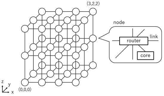
Figure 1.
Architecture of a 3D mesh NoC.
Each direction, east, west, south, north, up, and down, is also illustrated in Figure 1.
Figure 2 shows the architecture of each router in an NoC. A router consists of seven input/output buffers, a crossbar switch, and a routing controller. Input buffers store packets from adjacent routers or cores. Output buffers store packets from input buffers. The crossbar switch connects input buffers and output buffers. The routing controller controls the router. Each input/output port has several buffers to configure VCs. A VC is a communication channel that is virtually configured by sharing a single link in a time division manner. VCs enable one to multiplex the original network and configure multiple virtual networks (VNs). In Figure 2, two VCs are used for each input/output port to configure two VNs.
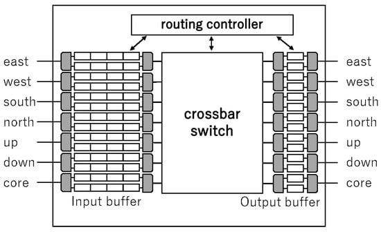
Figure 2.
Architecture of a router.
In this paper, we focus on node failures, as in many existing studies. This is because nodes consume a larger circuit area than those of links and are more prone to failure. Practically, the probabilities of links and additional circuits (such as switches, as employed in the proposed method) being faulty are not zero, although they will be substantially small because of the simplicity of their circuits. For their faults, some popular redundancy techniques, such as duplication and triplication, can be applied if necessary. We also assume, as in the existing studies, that the target network is connected; no node is isolated from the others.
2.2. Packet Routing
Packet routing is used to determine the appropriate output direction for each incoming packet in the input buffers in each router and move it to the chosen output buffer to forward it to the next router. A packet consists of data to be sent and a header in which destination information is stored. In NoCs, the typical wormhole routing is used. Therefore, packets are divided into smaller units called flits. There are three types of flits. The head flit contains routing information, such as the destination node. The body flit stores the divided data. The tail flit indicates the end of the packet. In each router, the head, body, and tail flits are forwarded in a pipeline fashion.
When the head flit of an incoming packet is stored in an input buffer, the following processes are applied in the router [22].
- An output port is chosen according to the information of the head flit.
- A VC to be used is selected for the chosen output port.
- The corresponding input and output buffers are connected via the crossbar switch.
- The flit in the input buffer is sent to the output buffer.
- The flit is sent to the neighbor node.
Each flit is forwarded to its output port in the above five cycles if there is no contention with other packets in the router.
2.3. Deadlock
Deadlock is a state in which each packet is waited for by another packet, and packets cannot be transferred forever. Figure 3 shows an example of a deadlock. In Figure 3, packet P1 in node N1 is interrupted by packet P2 in node N2. Packet P2 is also interrupted by packet P3. Similarly, packet P3 and packet P4 are interrupted by P4 and P1, respectively, forming a circular waiting cycle among the packets. Once a deadlock has occurred, no packet can proceed toward the destination. Therefore, deadlock freeness must be guaranteed in the employed routing method.
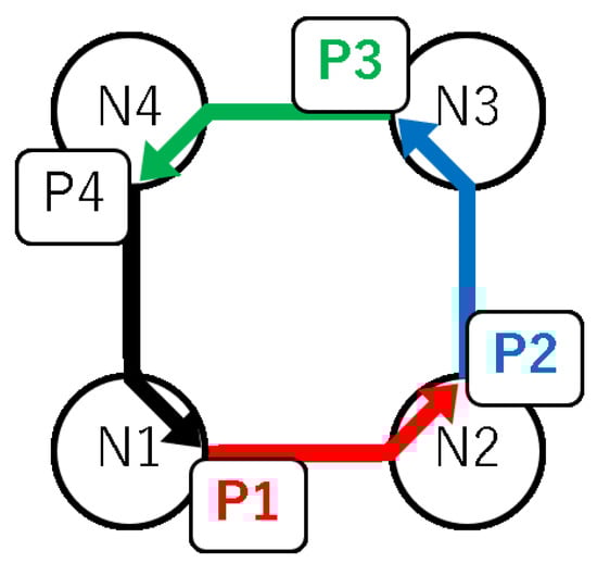
Figure 3.
An example of a deadlock.
2.4. Conventional Method
In this paper, we focus on the conventional method proposed by Boppana et al. [3], which guarantees deadlock freeness and 100% packet reachability. Boppana’s method creates minimally sized, rectangular, parallelepiped fault blocks (FBs) by enclosing a single faulty node or a cluster of connected faulty nodes. Thus, multiple FBs are usually created. This method performs the following two routing types in an NoC with multiple FBs:
- (a)
- Minimal fully adaptive routing;
- (b)
- Fault-tolerant routing.
In this method, first, routing (a) is performed to select an arbitrary shortest path and approach the destination node. When no shortest path can be selected, the current node and the destination node exist on a straight line on either the x, y, or z axes, and there is at least one FB on the straight line. In this case, the FB is detoured by routing (b) as the packets proceed along it.
In routing (b), a message is assigned for each packet to detour FBs. Packets detour FBs using a predetermined VC (i.e., VC0∼VC3).
Definition 1.
There are eight directions from a current node to a destination node, and . indicates that the destination node of a packet is on the + coordinate of the x-axis.
Definition 2.
Let be a plane that contains an i-axis and j-axis.
Table 2 shows the message types defined in Boppana’s method [3]. This table also shows the planes on which routing is performed, the VCs to be used, and the detour directions for FBs.
Table 2.
Message types of the existing method.
As shown in Table 2, in the fault-tolerant routing in Boppana’s method, the detour direction is fixed according to the message type. Thus, when a detour path is long, the communication latency becomes large. In addition, the hardware cost is high because four VCs are required to implement this fault-tolerant routing.
3. Proposed Methods
In this paper, we attempt to solve the problems of the conventional method with a method that enables adaptive routing (Proposed Method 1) and a method that enables the passage of FBs (Proposed Method 2) for (b) fault-tolerant routing.
3.1. Definitions
For the description of the proposed methods, we give the following definitions.
Definition 3.
The source node and the destination node of a packet and the current node where the packet currently exists are defined as , , and , respectively.
Definition 4.
Let the directions of east, west, north, south, up, and down be and and denoted by E, W, N, S, U, and D, respectively.
Definition 5.
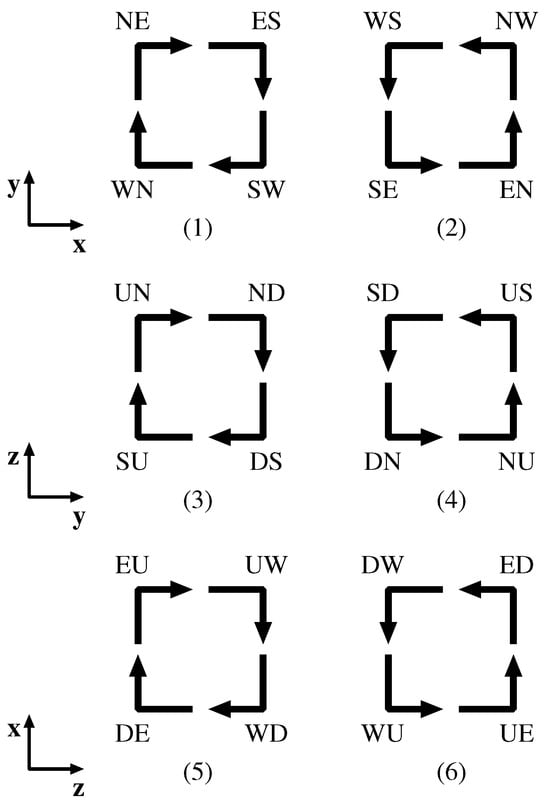
A change in the movement direction of a packet is defined as a turn. There exist 24 possible turns, as shown in Figure 4. For example, in an NE turn, a packet changes its moving direction from N to E at a router.
Figure 4.
Clockwise and counter-clockwise turns for each plane.
Definition 6.
There are eight diagonal directions, and the set of all diagonal directions is defined by {}.
Definition 7.
Let be the set of possible directions to take the shortest path from a node i to a node j.
Definition 8.
For a node i, let the direction of node j be .
3.2. Minimal Fully Adaptive Routing
Boppana’s method uses two different routing methods, routing (a) and (b), as explained in Section 2.4. For routing (a), minimal fully adaptive routing is used; however, their paper [3] does not mention the detailed routing rules. In this section, we briefly explain the minimal fully adaptive routing, , used in this paper.
performs adaptive routing by choosing a neighbor node at to take the shortest path from to . Algorithm 1 shows the algorithm of . First, for a packet originating at a source node , a VC to be used is determined according to (line 3 in Algorithm 1). Then, the packet can choose either one of the neighbor node directions from (line 8). For example, in the case of , {}, which means that a packet can proceed in direction E, N, or U.
The VC selection algorithm for is shown in Algorithm 2. The eight diagonal directions defined by are divided into four groups of two directions, each of which uses four different VCs (i.e., VC0∼VC3) to configure four VNs (lines 3–10). As for a direction d other than the diagonal ones, e.g., E and , any diagonal directions that include d are valid. For example, if , the VCs for , or , i.e., VC0∼VC3, can be chosen. If , the VCs for or can be chosen. Note that a determined VC is not changed when routing (a) is performed.
We now prove the deadlock freeness and 100% packet reachability of the presented .
Theorem 1.
shown in Algorithm 1 is deadlock-free in fault-free 3D mesh NoCs.
Proof of Theorem 1.
A deadlock occurs when several packets wait for one another to move forward (i.e., circular waiting). We show that circular waiting never occurs in both the clockwise and counter-clockwise directions in .
As shown in Algorithm 1, uses four VCs (i.e., VC0∼VC3) to configure four VNs in the original network. For a packet from to , once a VC is determined, it is never changed until the packet arrives at (line 3 in Algorithm 1), which means that the four VCs (i.e., VNs) are mutually independent.
First, we focus on VC0. In the VN configured by VC0, only packets whose or are routed. For , NE and EN, UE and EU, and UN and NU turns occur in the , , and planes, respectively. For , SW and WS, DS and SD, and WD and DW turns occur in the , , and planes, respectively. Even if all of these turns occur in one VN, they never cause circular waiting in the clockwise and counter-clockwise directions, as shown in Figure 4.
A similar statement as above holds for VC1∼VC3. Thus, is deadlock-free. □
Theorem 2.
shown in Algorithm 1 provides 100% packet reachability in fault-free 3D mesh NoCs.
Proof of Theorem 2.
As shown in Algorithm 1, always chooses a neighbor node from (line 8 in Algorithm 1). In other words, packets always move closer to . As the network is regular and there exist no faulty nodes, a packet originating at eventually reaches . This holds for any and . □
| Algorithm 1 Algorithm of . |
|
| Algorithm 2 VC selection algorithm of . |
|
3.3. Adaptive Fault-Tolerant Routing Method (Proposed Method 1)
We propose an adaptive fault-tolerant routing method, referred to as Proposed Method 1. This method also creates FBs in the same way as the conventional Boppana method [3], and it consists of the following two routing types:
- (a)
- Minimal fully adaptive routing: ;
- (b)
- Fault-tolerant routing: .
The difference between Proposed Method 1 and Boppana’s method is the adaptive fault-tolerant routing, . also uses the same number of VCs as in the conventional method; however, the method of using the VCs is different. With the same number of VCs, Proposed Method 1 allows the adaptive detour of FBs to shorten the distance from to .
As in the conventional method, when the routing is switched from (a) to (b), i.e., when the selection of the shortest paths becomes impossible, and exist on a straight line on the x, y, or z axes, and there exists at least one FB between and [3]. Here, we give the following definition.
Definition 9.
A node on a straight line passing through and and touching an FB on the opposite side to is defined as . Note that can be the same node as .
The routing algorithm of Proposed Method 1 is shown in Algorithm 3. First, a VC to be used is determined at . As Proposed Method 1 is a fault-tolerant routing method, different VC selections are performed for routing (a) and (b) (lines 4–9). As in the conventional method, is first performed as long as the shortest path can be selected (lines 13–14). When the selection of the shortest path is impossible, is switched to (lines 15–20). Then, a VC to detour an FB is determined according to the direction from to (line 17), and the FB is adaptively detoured by (line 20), so that the shortest detour path can be selected from to (lines 30–31).
The VC selection algorithm for is shown in Algorithm 4. When is initiated, , , and are on a straight line, as in the conventional method; that is, {}. For the six directions, only four VCs are used by sharing VC4 and VC6 among E, N, and U (lines 3, 7, 11–23) and VC5 and VC7 among W, S, and D (lines 5, 9, 25–37). With this careful VC sharing, Proposed Method 1 achieves deadlock freeness and 100% packet reachability, as discussed later.
Figure 5 shows a routing example for Proposed Method 1. In Figure 5, suppose that a packet is routed from to . At , and {}. Figure 5 shows an example where E is chosen as the next node. When the packet arrives at , the packet faces the FB and no shortest paths can be found. Then, the routing is switched to . In this example, two detour paths can be chosen, clockwise (solid line in Figure 5) and counter-clockwise (dotted line). By , the clockwise detour path is selected because it is shorter, and the packet can arrive at , detouring from the FB. Finally, the packet arrives at .
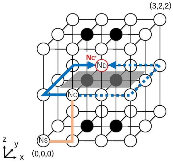
Figure 5.
A routing example for Proposed Method 1.
Note that Proposed Method 1 does not always provide the shortest paths. As explained above, if a packet adaptively proceeds in and arrives at , which exists on a straight line to , the routing is switched to to detour from the FB. In this case, the packet deviates from the shortest path. This problem is solved in another proposed method described in the next section.
We now prove the deadlock freeness and 100% packet reachability. Let be Proposed Method 1 shown in Algorithm 3.
Theorem 3.
is deadlock-free in 3D mesh NoCs.
Proof of Theorem 3.
As shown in Algorithm 3, consists of two routing functions, and ; is first adopted to proceed along the shortest path adaptively, and then it is switched to to detour around FBs. As long as is adopted, the deadlock freeness is guaranteed by Theorem 1. Hence, we discuss the deadlock freeness of .
When is switched to (i.e., ), and are on a straight line on either the x, y, or z axis, and there exists at least one FB between and (i.e., {}). detours from the FB using four VCs, VC4∼VC7, as shown in Algorithm 4.
First, we focus on VC4, in which packets with are routed (line 3 in Algorithm 4). In this case, although several possible turns occur to detour around the FB (i.e., EN, NE, ES, SE, UE, EU, DE, and ED turns), packets do not return in the opposite direction (i.e., ). Hence, circular waiting never occurs. VC4 is also used to route packets with (line 10 in Algorithm 4). In this case, several possible turns occur to detour around the FB (i.e., UE, UW, NU, and SU turns), as in the case of . Even if all of these turns occur in one VN simultaneously, they never cause circular waiting in the clockwise and counter-clockwise directions, as shown in Figure 4.
A similar statement as above holds for VC5, VC6, and VC7; thus, is deadlock-free. □
Theorem 4.
provides 100% packet reachability in 3D mesh NoCs.
Proof of Theorem 4.
is proven to provide 100% packet reachability in Theorem 2. Hence, we discuss the packet reachability of .
When is initiated, , , and are on a straight line, and there exists at least one FB, as explained before. surely detours around the FB from to , selecting the shortest path, as the network is connected. If there exist FBs between and , similar detours to the above are repeated by , eventually arriving at .
Thus, provides 100% packet reachability. □
| Algorithm 3 Algorithm of Proposed Method 1. |
|
| Algorithm 4 Proposed VC selection algorithm of . |
|
3.4. Passage-Based Fault-Tolerant Routing Method (Proposed Method 2)
Aiming at guaranteeing the shortest paths for all packets, we propose a novel fault-tolerant routing method based on the passage of faulty nodes, referred to as Proposed Method 2 in this paper. This method is an extension of Proposed Method 1. Namely, this method also creates FBs and consists of the following two routing types:
- (a)
- Minimal fully adaptive routing: ;
- (b)
- Fault-tolerant routing: .
The difference from Proposed Method 1 is . In Proposed Method 1, FBs are adaptively detoured, while, in Proposed Method 2, they are passed through.
To pass through FBs, the architecture proposed for 2D mesh NoCs in [12] is extended to 3D mesh NoCs, as shown in Figure 6. Switches and a link with a register are added to each link connected to the neighbor node in the x, y, and z directions. Once the node is judged as faulty with a circuit test technique, the switches are statically set so that packets are never input to the node and pass through it in the directions.
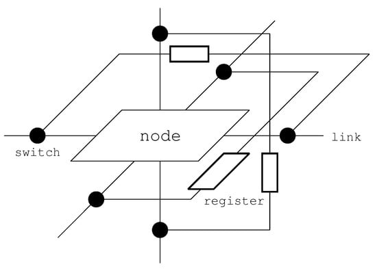
Figure 6.
Architecture that enables the passage of faulty nodes.
The routing algorithm of Proposed Method 2 is shown in Algorithm 5. The structure of the algorithm is almost the same as that of Algorithm 3. When is initiated, there exists an FB between and , as well as . In , packets can pass through the FB and reach directly from . Thus, does not require any VCs, as no turns are needed to avoid FBs, and Proposed Method 2 allows one to always take the shortest path from to .
Figure 7 shows a routing example for Proposed Method 2, for the same example case as in Figure 5. In this method, the packet proceeds from to by passing through the FB.
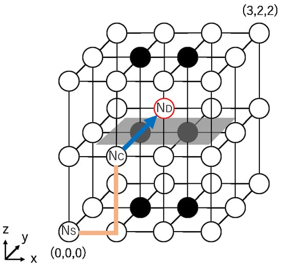
Figure 7.
A routing example for Proposed Method 2.
We now prove the deadlock freeness and 100% packet reachability. Let be Proposed Method 2, shown in Algorithm 5.
Theorem 5.
is deadlock-free in 3D mesh NoCs.
Proof of Theorem 5.
The proof is straightforward and similar to that of Theorem 3. To avoid redundancy, we provide a simple proof. , which combines and , is proven to be deadlock-free in Theorem 3. is the combination of and , and no turns occur in . Therefore, all possible turns in are a subset of those in . Thus, is deadlock-free. □
Theorem 6.
provides 100% packet reachability in 3D mesh NoCs.
Proof of Theorem 6.
Again, we provide a simple proof. provides 100% packet reachability, as proven in Theorem 4. The only difference between and is the way in which we proceed from to . As additional hardware such as links, switches, and registers is assumed to be fault-free, passage from to is always possible. Thus, also provides 100% packet reachability. □
| Algorithm 5 Algorithm of Proposed Method 2. |
|
4. Performance Evaluation
We evaluate the performance of the two proposed methods and compare them with the existing method [3]. We develop a cycle-accurate custom simulator in the C language, in which packets are forwarded to the destination nodes with standard five-cycle routers with VCs. We compare the average communication latency and network throughput of these methods. The communication latency is defined by the total cycles of a packet required to reach the destination node from its generation at the source node. The throughput is defined by the number of arrived packets per one cycle.
In the simulations, faulty nodes are randomly generated in a 3D mesh network according to the fault rate f before packet routing. Fault patterns in which the entire network is divided into multiple segments or one FB covers the entire network are excluded from this evaluation. Packets are generated in a uniform random manner in each cycle according to the packet generation rate p during the simulation period of 50,000 cycles. The average latency of arrived packets is not measured between 1∼5000 cycles to stabilize the network. These methods are simulated for the same fault patterns and the same packet generation patterns. Each trial is repeated 1000 times. The simulation parameters are listed in Table 3.
Table 3.
Simulation parameters.
4.1. Communication Performance
Figure 8a–e show the simulation results for and 3D mesh NoCs of nodes. In these figures, the horizontal axis represents the network throughput, and a larger value indicates higher performance. The vertical axis represents the average latency, and a larger value indicates more network congestion.
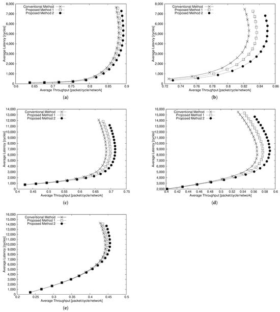
Figure 8.
Average latency vs. throughput (). (a) . (b) . (c) . (d) . (e) .
First, we compare the average latency of these methods. In the case of , when , Proposed Methods 1 and 2 reduce the average latency by up to about 19% and 30% compared with the existing method, respectively. In the case of , when , Proposed Method 1 reduces the average latency by up to about 2.9% compared with the existing method. When , Proposed Method 2 reduces the average latency by up to about 1.5% compared with the existing method.
Next, we compare the network throughput of these methods. In the case of , when , Proposed Methods 1 and 2 improve the network throughput by up to about 1.3% and 2.8% compared with the existing method, respectively. In the case of , when , Proposed Methods 1 and 2 improve the network throughput by up to about 1.3% and 3.1% compared with the existing method, respectively.
Figure 9a–e show the simulation results for and 3D mesh NoCs of nodes. For the communication latency, when , Proposed Methods 1 and 2 reduce the latency by about 16.8% and 26.8%, respectively, compared with the existing method. When , the two methods reduce the latency by about 2.9% and 4.7%, respectively. For the throughput, when , Proposed Methods 1 and 2 can improve the throughput by about 1.4% and 3.4%, respectively. When , the two methods improve the throughput by about 1.7% and 4.0%, respectively.
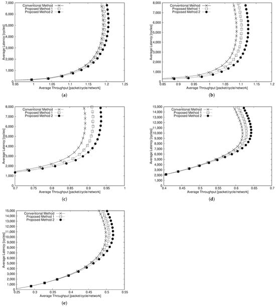
Figure 9.
Average latency vs. throughput (). (a) . (b) . (c) . (d) . (e) .
Note that all average values obtained in the simulations are confirmed to be within the 95% confidence interval.
The above results show that the communication latency of the proposed methods is higher than that of the existing method. However, when the fault rate is high (), the reduction in the average latency is smaller. Since the proposed methods and the existing method create FBs, the number of FBs becomes large. Thus, the detour path becomes long, or packets cannot pass through the FBs because the FBs touch the network boundaries.
4.2. Hardware Overhead
To evaluate the hardware overhead, we estimate the amount of circuits of the three methods. Let R be the number of circuits for a standard router without VCs. From reference [23], the number of circuits required to add one VC to all input ports of the router in a 3D mesh NoC is . Therefore, the number of circuits for a router using VCs can be indicated as . Proposed Method 2 requires additional links, switches, and registers, and the number of circuits required for passage in and z is according to reference [12].
Since the existing method and Proposed Method 1 use eight VCs, the number of circuits can be estimated as follows:
Since Proposed Method 2 uses four VCs, the number of circuits can be estimated as follows:
From the above, despite the addition of hardware, Proposed Method 2 can reduce the number of circuits by about 46% compared to the existing method and Proposed Method 1.
5. Conclusions
In this paper, we proposed two fault-tolerant routing methods. Proposed Method 1 allows adaptive detours for faulty regions and Proposed Method 2 allows the passage of them. To evaluate the performance of the proposed methods, we compared the average latency, the network throughput, and the amount of circuits. As a result, Proposed Method 2 enables us to reduce the latency by about 30% and improves the throughput by about 3.1% with half the virtual channels.
Future work will include the development of a new routing method that satisfies deadlock freeness and 100% packet reachability for convex and non-convex FBs.
Author Contributions
Conceptualization, Y.K. and M.F.; methodology, Y.K. and M.F.; software, Y.K.; validation, Y.K. and M.F.; formal analysis, Y.K. and M.F.; investigation, Y.K. and M.F.; resources, Y.K. and M.F.; data curation, Y.K. and M.F.; writing—original draft preparation, Y.K.; writing—review and editing, Y.K. and M.F.; visualization, Y.K. and M.F.; supervision, M.F.; project administration, Y.K. and M.F.; funding acquisition, M.F. All authors have read and agreed to the published version of the manuscript.
Funding
This research was funded by JSPS KAKENHI grant number JP21K11810.
Institutional Review Board Statement
Not applicable.
Informed Consent Statement
Not applicable.
Data Availability Statement
The data are available upon request from the authors.
Conflicts of Interest
The authors declare no conflicts of interest.
References
- Sarihi, A.; Patooghy, A.; Khalid, A.; Hasanzadeh, M.; Said, M.; Badawy, A.H.A. A Survey on the Security of Wired, Wireless, and 3D Network-on-Chips. IEEE Access 2021, 9, 107625–107656. [Google Scholar] [CrossRef]
- Jain, A.; Kumar, A.; Shukla, A.P.; Alshazly, H.; Elmannai, H.; Algari, A.D.; Kumar, R.; Yadav, J. Smart Communication Using 2D and 3D Mesh Network-on-Chip. Intell. Autom. Soft Comput. 2022, 34, 2007–2021. [Google Scholar] [CrossRef]
- Boppana, R.V.; Chalasani, S. Fault-Tolerant Wormhole Routing Algorithms for Mesh Networks. IEEE Trans. Comput. 1995, 44, 848–864. [Google Scholar] [CrossRef]
- Jouybari, H.N.; Mohammadi, K. A low overhead, fault tolerant and congestion aware routing algorithm for 3D mesh-based Network-on-Chips. Microprocess. Microsyst. 2014, 38, 991–999. [Google Scholar]
- Zhou, J.; Li, H.; Wang, T.; Li, X. LOFT: A low-overhead fault-tolerant routing scheme for 3D NoCs. Integration 2016, 52, 41–50. [Google Scholar]
- Charif, A.; Coelho, A.; Ebrahimi, M.; Bagherzadeh, N.; Zergainoh, N. First-last: A cost-effective adaptive routing solution for tsv-based three-dimensional networks-on-chip. IEEE Trans. Comput. 2018, 67, 1430–1444. [Google Scholar]
- Salamat, R.; Ebrahimi, M.; Bagherzadeh, N.; Verbeek, F. Cobra: Low cost compensation of tsv failures in 3d-noc. In Proceedings of the IEEE International Symposium on Defect and Fault Tolerance in VLSI and Nanotechnology Systems, Storrs, CT, USA, 19–20 September 2016; pp. 115–120. [Google Scholar]
- Dubois, F.; Sheibanyrad, A.; Pétrot, F.; Bahmani, M. Elevator-first: A deadlock-free distributed routing algorithm for vertically partially connected 3d-nocs. IEEE Trans. Comput. 2013, 62, 609–615. [Google Scholar]
- Akbari, S.; Shafiee, A.; Fathy, M.; Berangi, R. Afra: A low cost high performance reliable routing for 3d mesh nocs. In Proceedings of the Design, Automation Test in Europe Conference Exhibition, Dresden, Germany, 12–16 March 2012; pp. 332–337. [Google Scholar]
- Ebrahimi, M.; Daneshtalab, M.; Liljeberg, P.; Tenhunen, H. Fault-tolerant method with distributed monitoring and management technique for 3d stacked meshes. In Proceedings of the International Symposium on Computer Architecture Digital Systems (CADS), Tehran, Iran, 30–31 October 2013; pp. 93–98. [Google Scholar]
- Guo, P.; Hou, W.; Guo, L.; Sun, W.; Liu, C.; Bao, H.; Duong, L.H.K.; Liu, W. Fault-Tolerant Routing Mechanism in 3D Optical Network-on-Chip Based on Node Reuse. IEEE Trans. Parallel Distrib. Syst. 2020, 31, 547–564. [Google Scholar]
- Kurokawa, Y.; Fukushi, M. Passage of Faulty Nodes: A Novel Approach for Fault-Tolerant Routing on NoCs. IEICE Trans. Fundam. Electron. Commun. Comput. Sci. 2019, E102-A, 1702–1710. [Google Scholar]
- Da Silva, A.A.; E Silva Junior, L.M.; Coelho, A.; Silveira, J.; Marcon, C. Reflect3d: An Adaptive and Fault-Tolerant Routing Algorithm for Vertically-Partially-Connected 3D-NoC. In Proceedings of the 2021 34th SBC/SBMicro/IEEE/ACM Symposium on Integrated Circuits and Systems Design (SBCCI), Campinas, Brazil, 23–27 August 2021; pp. 1–6. [Google Scholar]
- Da Silva, A.A.; Nogueira, L.; Coelho, A.; Silveira, J.A.N.; Marcon, C. Securet3d: An Adaptive, Secure, and Fault-Tolerant Aware Routing Algorithm for Vertically–Partially Connected 3D-NoC. IEEE Trans. Very Large Scale Integr. (VLSI) Syst. 2025, 33, 275–287. [Google Scholar] [CrossRef]
- Jayshree; Seetharaman, G.; Pati, D. Reliable Fault-Tolerance Routing Technique for Network-on-Chip Interconnect. In Proceedings of the Intelligent Sustainable Systems, Online, 17–19 March 2021; Springer: Singapore, 2022; pp. 767–775. [Google Scholar]
- Jagadheesh, S.; Bhanu, P.V.; Soumya, J.; Cenkeramaddi, L.R. Reinforcement Learning Based Fault-Tolerant Routing Algorithm for Mesh Based NoC and Its FPGA Implementation. IEEE Access 2022, 10, 44724–44737. [Google Scholar] [CrossRef]
- Khalil, K.; Eldash, O.; Kumar, A.; Bayoumi, M. Self-Healing Router Approach for High-Performance Network-on-Chip. IEEE Open J. Circuits Syst. 2021, 2, 485–496. [Google Scholar] [CrossRef]
- Khalil, K.; Kumar, A.; Bayoumi, M. Dynamic Fault Tolerance Approach for Network-on-Chip Architecture. IEEE J. Emerg. Sel. Top. Circuits Syst. 2024, 14, 384–394. [Google Scholar]
- Reddy, B.N.K.; Zia Ur Rahman, M.; Lay-Ekuakille, A. Enhancing Reliability and Energy Efficiency in Many-Core Processors Through Fault-Tolerant Network-on-Chip. IEEE Trans. Netw. Serv. Manag. 2024, 21, 5049–5062. [Google Scholar] [CrossRef]
- Takanami, I.; Fukushi, M.; Watanabe, T. Self-restructuring of Mesh-Connected Processor Arrays with Spares Assigned on Rotated Orthogonal Side. In Transactions on Computational Science XXXVIII; Springer: Berlin/Heidelberg, Germany, 2021; pp. 36–53. [Google Scholar]
- Ding, H.; He, Y.; Zhai, Z.; Li, Z.; Qian, J.; Zhao, L. Efficient 3-D Processor Array Reconfiguration Algorithms Based on Bucket Effect. IEEE Trans.-Comput.-Aided Des. Integr. Circuits Syst. 2024, 43, 1023–1036. [Google Scholar] [CrossRef]
- Dally, W.J.; Towles, B. Principles and Practices of Interconnection Networks; Morgan Kaufman Publishers: Burlington, MA, USA, 2004. [Google Scholar]
- Lin, S.Y.; Shen, W.C.; Hsu, C.C.; Wu, A.Y. Fault-Tolerant Router with Built-In Self-test/Self-diagnoses and Fault-Isolation Circuits for 2D-Mesh Based Chip Multiprocessor Systems. Int. J. Elect. Eng. 2009, 16, 213–222. [Google Scholar]
Disclaimer/Publisher’s Note: The statements, opinions and data contained in all publications are solely those of the individual author(s) and contributor(s) and not of MDPI and/or the editor(s). MDPI and/or the editor(s) disclaim responsibility for any injury to people or property resulting from any ideas, methods, instructions or products referred to in the content. |
© 2025 by the authors. Licensee MDPI, Basel, Switzerland. This article is an open access article distributed under the terms and conditions of the Creative Commons Attribution (CC BY) license (https://creativecommons.org/licenses/by/4.0/).