Abstract
Understanding the corrosion mechanism inside waste incinerators is very important in order to prevent possible damage due to high operational temperatures in chemical reactions for burning raw hazardous materials. Moreover, it is critical to understand the corrosion mechanisms to identify whether the oxides formed are protective or not, enabling us to prevent mass change on the steel walls of heat exchangers in waste incinerators. Thus, the present work comprises a high-temperature corrosion study on four Ferritic alloys with different contents of Al, Si, and Mo which are capable of replacing expensive materials such as stainless steel. The corrosion behavior was evaluated in atmospheres with H2O(g), HCl(g), and an additional mixture of both atmospheres at 500 and 600 °C over 300 h. A thicker but porous heterogeneous oxide scale was formed in the HCl atmosphere, mainly composed of Fe2O3 and Cr2O3. Under the water vapor atmosphere, the presence of (Fe0.6Cr0.4)2O3 was observed. Meanwhile, in the mixed atmosphere, the presence of FeCr2O4, Cr2SiO4, and (CrFe)2O3 was observed. The biggest mass loss was measured inside the water vapor atmosphere. In comparison, inside the mixed atmosphere, the oxide scale was thinner. Finally, it was concluded that the alloy with the best corrosion resistance in HCl and H2O atmospheres was Fe9Cr1.5AlSi3Mo steel.
1. Introduction
The reason for increasing the temperature in waste incinerators and power plants is to reduce harmful emissions as much as possible [1,2,3,4]. Thus, a material with good performance under high temperatures is required; stainless steel is frequently used for this purpose due to its good oxidation resistance; unfortunately, it is very expensive and its protective scale decreases at high temperatures, both in steam and in exhaust environments [5,6,7,8,9]. The chemical reactions over the metal surfaces continue to generate new products and reactions due to the aggressivity of the atmospheres. Consequently, volatile metal chlorides are formed over the metal/oxide interface which are evaporated and dragged, allowing for the displacement of oxides and chlorines and the continuity of the corrosion process; subsequently, these are diffused outwards and converted into oxides, which are placed in regions with high oxygen partial pressure [3,4,5,6,7,10,11,12,13,14]. Moreover, the burning process in waste incineration generates very corrosive combustion products due to the heterogeneous composition of waste. The quality or chemical composition of waste is complicated to control because it depends on careful selection; thus, a rare mix of materials that cannot be reused or are not recyclable are frequently sent to incinerators. In particular, chlorines generated from certain compounds demand higher temperatures for combustion, producing several forms of damage inside boilers [3,4,5,12,13,14,15,16,17,18]. Thus, it is important to understand the individual effect of each component on the corrosion phenomena that make up the atmosphere of a waste incinerator [4,5,6,7,10,11,12].
Corrosion at high temperatures inside heat exchangers is the main factor that limits the efficiency of various energy systems [4,5,6,7,19,20,21,22]. High-temperature corrosion of ferritic alloys and stainless steel using chlorine affects performance in several applications, such as municipal waste incinerators. Here, HCl is formed from burning PVC and other plastics and hazardous chemical residues, or from power plants using chlorine-bearing coal [9,10,11,12,13,14,15,16,17,21,22,23]. The residual oxygen in industrial burning is typically about 5–10 vol%; in contrast, HCl is only 0.0025 vol% in the gas flow of municipal waste incinerators. However, this quantity is enough to accelerate corrosion in many stainless steels and produce dangerous damage or failure [8,9,10,12,13,14,19,24]. Moreover, it is known that the presence of chlorine prevents the formation of protective oxides under certain conditions and causes an accelerated attack. Some authors have worked with iron and iron–chromium alloys and observed that even small changes in temperature or in the oxygen/chlorine ratio affect corrosion behavior [8,9,10,11,12,13,14]. Some previous studies [15,16,17,18,19,20,24,25,26,27] were carried out considering steels with a very high content of Mo or Cr. Unfortunately, it was very difficult to manufacture these alloys due to their extreme hardness [7,8,9,10,11,15,16,17,18,25,28,29,30,31,32]. Thus, the Mo content had to be significantly reduced so that these alloys could be used for the walls of tubes inside heat interchanges and furnaces [8,9,10,11,12,28,29,30,31,32,33,34]. Furthermore, low concentrations of water, HCl, and a mixture of both of these were also selected to simulate aggressive environments, all of which are found in real industrial waste incinerators, enabling us to study their influence independently and in mixed aggressive fluxes [15,16,17,20,21,22,23,27,28,29,33,35,36,37].
It is important to highlight the importance of understanding corrosion, and many authors have conducted studies according to particular operating conditions and waste compositions [15,20,21,22,23,34,38,39,40,41]. Other authors have tested different metallic materials, the most common of which are aluminum alloys and different kinds of steel; these represent the most used metallic materials. Moreover, many mechanical components are made with different Fe alloys and work under different corrosive conditions [12,13,14,15,16,17,18,19,20,24,25,26,27,35]. Chemical reactors, tanks, furnaces, and boilers are used in industries containing solids, liquids, and gases which can cause fatigue and trigger chemical reactions inside deposits [18,25,26,27,28,29,30,31,33,35]. Many previous authors had to reproduce aggressive environments using laboratory instruments and devices [25,26,27,35,40,41,42,43,44]. Consequently, they had to build their own enclosed devices or work inside furnaces or stoves to reproduce the environment and maintain good control over the atmosphere [16,17,18,38,39,40,41,42].
Other authors have dedicated their research to finding evidence of the chemical activity of walls in contact with aggressive agents. Sometimes, protective hard scales are formed, mainly comprising hard oxides from aluminum or chromium [5,6,7,8,9,10,11,15,20,21,22,23,31,33]. Due to these scales, the metal surfaces avoid corrosion as the chemical reactions reoccur [26,27,35,36,37,40,41,42,43,44,45]. Nevertheless, frequently, such scales are weak and can be destroyed due to the motion of fluid and gaseous substances, allowing the corrosion process to continue and resulting in mass loss and damage to mechanical pieces [18,25,26,27,28,29,30,31,33,35]. Some authors have characterized the scale composition to elucidate the chemical reactions that occurred and have measured the scale thickness and hardness, exploring the relationship with the mass lost in the materials [13,14,24,29,30,31,32,34,38,39,40]. Moreover, temperature is one of the most important thermo-dynamical variables involved in corrosion as it can accelerate the degradation of components [9,10,11,12,13,14,15,20,21,22,23,31,32,34,38,39,46,47,48]. Additionally, understanding corrosion at high temperatures is very important because many mechanical components work in contact with each other, causing friction, increasing the heat interchange, and elevating temperatures [12,13,14,17,18,19,24,25,26,27]. Accordingly, in the present study, we established temperature ranges to analyze each case and proposed feasible solutions to increase the lifetime of alloys; some of our suggestions are based on preventive actions that can be taken to reduce corrosion damage as follows:
- (a)
- Promoting the formation of hard protective scales can help avoid corrosion; however, this depends on the waste composition and the sensibility of the metal alloy wall. Moreover, the type of waste being burned affects the reduction in chemical activity. Thus, it is difficult to control such processes [16,17,18].
- (b)
- The use of an additive coating to protect the components is another effective way to reduce corrosion; however, high temperatures affect their performance. A better option could be to employ a more resistant alloy in the walls.
In this study, 500 and 600 °C were the temperatures analyzed as they represent the temperature range in industrial conditions. These temperatures are extremely high in comparison with 233 °C, which is the temperature required of paper auto-ignition; 160–210 °C, which is the temperature required to burn PVC; or 400 °C, required for burning many plastics like polyethylene, polypropylene, or nylon. Many researchers have studied the influence of this temperature range on corrosion [4,5,6,7,13,23,28,29,30,43,44,45,46,47,48,49].
High temperatures inside waste incinerators make it nearly impossible to apply any cathodic or anodic protection procedure. The most used methods to avoid corrosion are based on the isolation of walls and components made of a precise alloy which is as inert as possible under an aggressive environment. Consequently, it is important to understand the individual effect of each component on the corrosion phenomena that make up the atmosphere of a waste incinerator [4,5,6,7,10,11,12,46,47,48]. Moreover, there are studies on incinerators in which the operational temperatures reach 1000 or 1200 °C; some of these studies have analyzed the formation of reactants like alumina and chromium, whereas others have studied the interaction between the aggressive environment and the influence of certain alloy elements such as Cr, Ni, Mo, or Al [49,50,51,52].
2. Experimental Procedure
Here, we describe the preparation of the alloys to be tested and the laboratory equipment used to reproduce the corrosive atmosphere conditions; moreover, we provide a brief explanation of the post-treatment process, the measurement of the corrosion products, and the use of scanning electron microscopy and XRD for analysis.
2.1. Preparation of Samples
The samples were prepared in a laboratory as follows: The chemical composition of the Fe-Cr alloys used in this research is shown in Table 1. The Fe-Cr alloys were prepared by induction melting using commercial low-carbon steel with the addition of alloying elements; de-carburization and de-oxidation practices were applied for cleaning and preparing. The alloy samples were cast in 150 × 150 mm square ingots. Longitudinal bars from the middle of the square section were cut; these samples were thermo-mechanically processed in order to refine the microstructure and provide ductility, even in the presence of the precipitates formed. The precipitates formed during melting ranged in size from 0.5 to 5 microns. The test specimen size was 10 × 10 mm, and these were cut into squared samples with a thickness of 2 mm. The specimens were prepared using SiC sandpaper of 600-grit and then cleaned using acetone. Finally, the samples were plunged in an ethanol solution using an ultrasonic bath before weighing [3,4,5,6,7,8,16,17,18,25,26,27].

Table 1.
Alloys composition (mass%), every alloy is a steel based containing 0.08 C.
2.2. Preparation of Aggressive Atmospheres
The three aggressive atmospheres were reproduced inside a SiO2-quartz glass tube for testing. Initially, N2 liquid flowing inside the electrical furnace in which the samples were placed was directed toward the hermetic device. The temperature was set using the thermometer of the furnace.
The first atmosphere contains 360 vppm H2O, the second contains 220 vppm HCl, and the third atmosphere comprised a mixture of 220 vppm HCl and 360 vppm H2O. The air remaining inside the furnace was not purged as this device was not incorporated in the furnace. Thus, it can be considered that certain quantities of O2 were present under the initial conditions. The laboratory tests were conducted assuming a constant fluid flow under isothermal conditions at 500 °C and 600 °C in a horizontal furnace with an inner diameter of 50 mm. The flow rate measured for all the experiments at the furnace inlet was 4 cm3/s.
The concentrations often found inside industrial incinerators are 360 and 220 vppm of H2O and HCl, which are considered low but sufficient to produce serious corrosive damage. The incinerator walls are frequently made of steel or stainless steel, conferring a longer lifetime, but the vapor concentration of these aggressive gases produces chemical reactions forming iron oxides and chlorines. Thus, understanding the corrosion mechanism is very important so that we can take action to protect the walls [4,5,6,7,8,18,25,26,27,35,46,47,48].
The experimental test set-up is shown in Figure 1. Exposure during the experiments was considered discontinuous. The post-exposure samples were weighed after 1, 3, 10, 30, 100, and 300 h, enabling us to analyze the influence of short- and long-term exposure. The samples were then taken out of the furnace and tested in pairs under the same atmosphere for each exposure duration. The first sample was used to measure the mass change. The corrosion products were removed using chemical etching in a KMnO4 solution at 80 °C; after this, the samples were cleaned inside a NaOH ultrasonic bath [4,5,6,7,22,24,26]. Finally, these samples were purified in an acetone solution. The second sample was characterized using a High-Resolution scanning electronic microscope (HR-SEM) Jeol 6701F, coupled with EDS using an acceleration voltage of 20 kV and X-Ray Diffraction using a Brucker D8 Focus (XRD), in order to characterize the surface scale and every corrosion product.
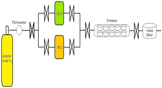
Figure 1.
An elementary sketch of the set-up for reproducing and controlling the aggressive atmospheres in the high-temperature corrosion experiments.
In the left side of Figure 1, a cylinder of nitrogen (N2) is shown; this inert gas draws the aggressive HCl and H2O towards the furnace where the samples are set. The valves allows a single aggressive gas or a mix of them to pass through. Inside the furnace, a water filter is positioned at the end of the set-up. The system is assumed to be closed or without mass interchange. O2 does not participate because it is absent in the system; furthermore, the environment is cleaned with a mechanical pump after every experiment to extract the residual gases.
Small quantities of oxygen were found at the end of the system as a result of incomplete oxidation of iron in the samples, identified as part of the metal oxides; nevertheless, it is difficult to measure O2 due to its extremely small volume, and it can only be measured when it is separate from metal oxides. Furthermore, this gas would leak very quickly as it is dragged by the N2 and the large volumes of HCl and H2O. These compounds were initially boiled using burning lamps at 60 °C, transforming into vapor, and then they were dragged with the N2. The valves were opened to control the passage of the O2 measured at the end of the set-up, resulting from an incomplete chemical reaction inside the furnace. Moreover, O2 is not considered a gas inside the furnace because it was evacuated with a pump after every test. Thus, its influence is negligible.
3. Analysis of Sample Morphology
The surfaces of each alloy showed different types of damage after having been exposed to the aggressive atmospheres. Different colors were found in the scanning electron microscopy analysis, such as gold, purple, and blue, which were analyzed to elucidate the scale thickness. The four alloys exposed to N2 containing 220 vppm HCl vapor at 500 °C for 300 h showed a homogeneous multi-scale oxide, whose morphology is shown in Figure 2a–d, formed mainly with iron and chromium oxides, identified via a mapping element over the material surface. The scales have the typical morphology of iron oxide whiskers due to active oxidation. Additionally, holes can be observed on the surface of the deposits and between the formed oxides and the base alloy; this evidences an active oxidation process [15,16,19,20,21,22,23,28,29,30,33,35,36,37,40,41,42,43,44].
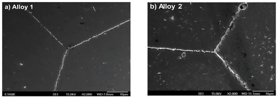
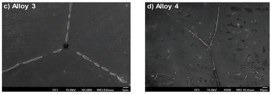
Figure 2.
The grain structures of the four alloys analyzed in this work, showing similar grain features on the grain boundaries and vertexes.
Figure 2a–d show scanning electron microscopy images of the grain boundaries and vertexes of the four alloys. Here, we can see similar structures and geometrical features of the grains. In addition, Figure 3a–h show the elemental mapping of alloy 4 exposed to water vapor at 500 °C as an example illustrating the presence of the main alloying elements. Here, the color intensity represents the presence of elements.
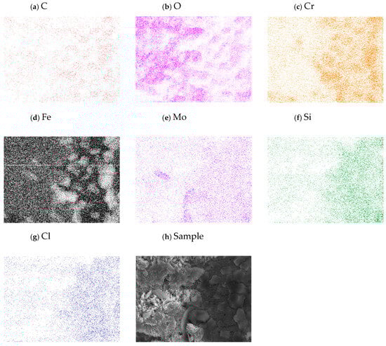
Figure 3.
Elemental mapping of the sample showing the composition of the elements on the metal base.
Figure 4a corresponds to alloy 1. Here, a notorious scale formation can be seen, homogeneous and thicker than that shown in Figure 4b. In this alloy, the scale is not well formed; the black points represent the base alloy where the whiskers with the protective scale were not grown. Deep sanding lines can be observed, suggesting a non-homogeneous scale formation, nearly inexistent in some places. In Figure 4c,d, the whiskers begin to grow but these do not form a homogeneous coat over the surface. As a result, some irregularities and pitting appear on the scale surface. In Figure 4d, the metal chlorides are shown by the dark areas, illustrating the incubation period (period when oxides are formed). It is important to mention that the chlorides are formed first as this is the initial chemical reaction, whereas oxides are formed as a result of the previous process in the active environment.
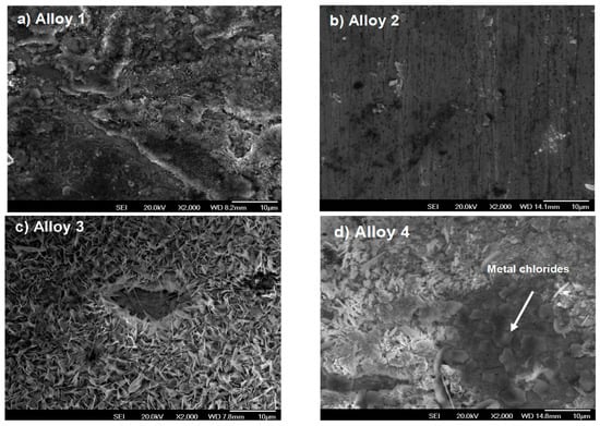
Figure 4.
Surface morphologies of Fe-Cr alloys corroded in N2 containing 220 vppm HCl vapor at 500 °C for 300 h.
Figure 5a–d correspond to the four alloys exposed in the 220 vppm H2O atmosphere at 600 °C for 300 h. Figure 5a shows the poorest scale formation. Here, only some isolated oxide regions can be observed where the protective scale was not consolidated. In contrast, in Figure 5b, some little whiskers begin to appear, although they are not sufficiently grown. In Figure 5c, a better scale formation is shown. Nevertheless, some holes and irregularities remain. In contrast, in Figure 5d, the whiskers are clearly defined and a homogeneous scale formation is shown. This is the best protective scale formed, and no holes or irregularities can be seen on the sample surface.
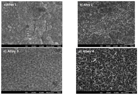
Figure 5.
Surface morphologies of Fe-Cr alloys corroded in N2 containing 360 vppm H2O vapor at 600 °C for 300 h.
The micrographs shown in Figure 6a–d correspond to steels exposed to a mixture of 220 vppm HCl and 360 vppm H2O for 300 h. Here, the oxide formed is not homogeneous and the sanding lines of the post-polishing process can be clearly observed in all figures. The oxide is formed over the sanding lines as these zones promote corrosion due to having the largest reaction area; additionally, the presence of Fe and Cr oxides can be observed. This fact was validated via surface mapping and XRD analysis.
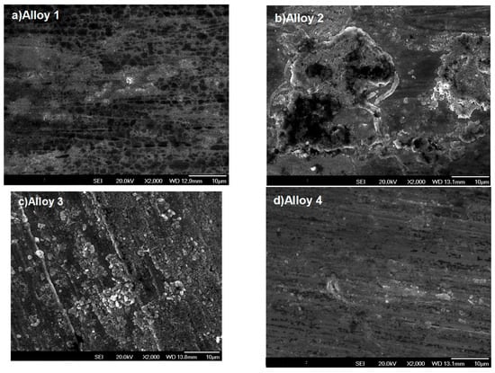
Figure 6.
Surface morphologies of Fe-Cr alloys corroded in N2 containing 360 vppm H2O and 220 vppm HCl vapor at 600 °C for 300 h.
4. Thermogravimetric Analysis
The thermogravimetric curves for the four alloys studied at 500 °C and 600 °C for 300 h in 360 vppm H2O and N2-220 vppm HCl are shown in Figure 7 and Figure 8, respectively. The results indicate that the corrosion rate for the Fe-Cr alloys is faster in H2O, especially at 600 °C. The parabolic shape of the curves indicates accelerated corrosion due to the diffusion of oxygen in the oxide scales until 50 h. In contrast, for the HCl atmosphere, an irregular behavior during the incubation period is observed. During this initial period, a reduction in the mass change is observed in the HCl atmosphere. Moreover, the corrosion process continues with an increment in mass change of the water vapor until 100 h; however, the corrosion seems become passive after long exposure durations. Furthermore, corrosion is always increasing as the protective scale is not hard enough to inhibit the chemical reaction in the aggressive atmosphere. The samples exposed to H2O show a notorious increment in the corrosion rate at 600 °C in comparison with samples exposed to 500 °C. Thus, we can conclude that the most aggressive atmosphere is water. This conclusion is supported by Figure 7 and Figure 8, revealing that the mass change is significant in Figure 7. Moreover, the results show that the atmosphere with HCI is less aggressive due to the absence of oxygen.
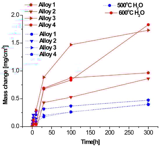
Figure 7.
Thermogravimetric results for corrosion at 500 and 600 °C in N2-360 vppm H2O.
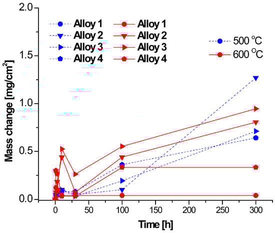
Figure 8.
Thermogravimetric results for corrosion at 500 and 600 °C in N2-220 vppm HCl.
The experimental test was repeated five times with eight samples inside the furnace to ensure validity on every set, and the results were averaged. In Figure 7, we can observe the mass change of the four alloys. All alloys at 500 and 600 °C begin with a small mass change and exhibit small variations over longer exposure periods; at 600 °C, the mass change increases as a result of the increment in chemical activity.
As shown in Figure 8, the highest values of mass change are almost 1.25 but are rarely counted; as can be seen in the vertical axes on Figure 7 and Figure 8, the major mass change occurs in the H2O atmosphere. These results suggest that, over longer exposure durations, corrosion nearly stops. However, there is a notorious corrosion period between 20 and 100 h.
Chlorines of Fe are volatiles after short exposure durations; however, corrosion is reduced when these are formed, as can be seen in the beginning of all curves shown in Figure 7 and Figure 8, Nevertheless, as these volatiles are removed due to fluid movement, corrosion starts again after 50 h. Many authors have suggested that mass loss is linked to the metal base reaction, using high-precision balances to measure mass loss in every aggressive atmosphere; others authors refer to mass gain, which is attributed to the chlorines and oxides deposited in the metal base after exposure to an aggressive atmosphere, with mass gain measured according to the weights before and after corrosion. Other authors use the net weight interchange, known as the mass change. In Figure 7, Figure 8 and Figure 9, the initial 100 h correspond to the beginning of the corrosion process, and chemical reactions are defined as a function of the aggressive atmosphere here; for longer exposure periods, some of the slopes tend to horizontally curve, indicating that the reactions are slowing down and corrosion is reducing. This suggests that hard oxides or some protective scale has been formed on the surface, limiting the corrosion process. Figure 7, Figure 8 and Figure 9 shown the corrosion process as a function of the aggressive environment, and Figure 10, Figure 11 and Figure 12 present the mass change analysis.
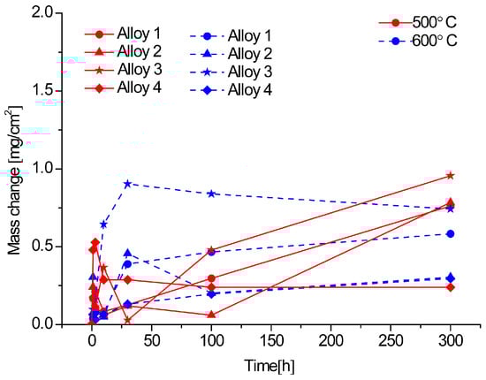
Figure 9.
Thermogravimetric results for corrosion at 500 and 600 °C in N2-360 vppm H2O and 220 vppm HCl for 300 h.
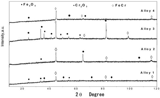
Figure 10.
XRD patterns of oxide scales formed on Fe Cr alloys corroded for 300 h in N2 220 vppm HCl at 500 °C.
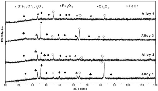
Figure 11.
XRD patterns of oxide scales formed on Fe Cr alloys corroded for 300 h in N2 360 vppm H2O at 600 °C.
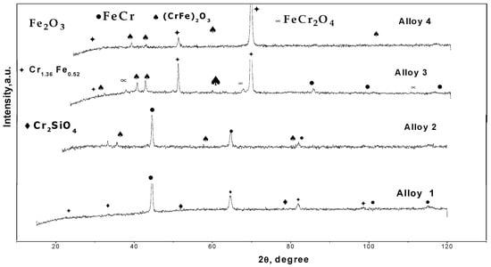
Figure 12.
XRD patterns of oxide scales formed on Fe Cr alloys corroded for 300 h in N2-360 vppm and H2O 220 vppm HCl at 500 °C.
Figure 9 shows the thermogravimetric results for the alloys studied in N2-360 vppm H2O and 220 vppm HCl at 500 °C and 600 °C for 300 h (the mixed atmosphere); here, alloy 4 at 500 °C is the least corroded. It can also be seen that many of the alloys at these temperatures show a parabolic regime. However, the incubation period is not regular at the beginning. The parabolic curves indicate that the growing oxide acts as a barrier against both anions and cations; moreover, the temperature affects the formation of the oxide scale. In this figure, there is an unstable scale formation period until 100 h. Here the major mass change is almost 1 mg/cm2; then, it is possible to affirm that, it is the less aggressive environment.
5. XRD Analysis
The XRD results of the formed oxide scales are shown in Figure 10, Figure 11 and Figure 12. Here, the presence of Fe2O3 can be observed. In addition, low quantities of Cr2O3 and (Fe0.6Cr0.4)2O3 are present as the main compounds produced via oxidation. These results are in good agreement with studies conducted by other authors [7,15,16,22,23,28,29,30,31,33]. In some samples, the major peaks of the basis Fe-Cr alloy are observed because the oxide scales are not thick enough, allowing them to be penetrated by the X-rays.
The corrosion products identified after 300 h of exposure in N2-360 vppm H2O and 220 vppm HCl were CrSiO4, (Cr,Fe)2O3, and FeCr2O4; here, the oxide properties critically depend on the composition of each alloy and the potential reaction with the atmosphere. Chromia-rich oxide is protective, whereas iron-rich oxide is poorly protective. Iron oxide is porous, weak, and did not adhere to Fe-Cr surfaces because it was removed by the fluid flowing inside the furnace, increasing the total mass loss. Additionally, the presence of Fe-Cr can be seen in the diffractograms obtained at both temperatures, suggesting that X-rays penetrate the porous oxide scale because they are so thin, and the base metal spikes can be detected using laboratory equipment. Nevertheless, there were no detected compounds resulting from the interaction between the aggressive atmospheres and the rest of the alloy elements (Al, Si, and Mo). This result can be attributed to the low concentration of these elements in the four alloys [5,6,7,8,9,10,11,18,25,26,27,35,39,40,41,42,43].
6. Mass Change Analysis
The highest mass change was observed for alloy 4 in the environment containing H2O. The corrosive attack was more accentuated in H2O than in HCl or in the mixed atmosphere for all alloys because the water vapor acts as an oxidizing agent, increasing the formation of Cr and Fe oxides. Steels can be made more corrosion-resistant by adding certain alloying elements such as Al, Si, and Cr, which form protective oxides [1,2,3,4,7,8,9,10,11,19,20,21,22,24]. Although the alloys tested contain Si, Mo, and Al, no chemical products resulted from their presence. This is likely due to their low concentration in the metal base. Alloy 3 presented a moderate mass loss. In contrast, alloys 1 and 4 were more severely degraded under the water environment at 500 °C, as illustrated in Figure 13a. Alloy 2 showed the best performance in all environments. Water is the most aggressive environment; the mixed atmosphere is an intermediately aggressive environment; and the HCl(g) atmosphere is the less reactive, evidenced by the mass change only falling between 30 and 40%. The corrosive behavior of the four alloys at 600 °C is shown in Figure 13b. Here, it is possible to observe that alloy 4 was dramatically attacked under the water atmosphere despite containing the greatest amount of Al and Si. The rest of the alloys only experienced moderate mass change. The graphs in Figure 13a,b show the oxides in the metal base. The weight of the material is considered the mass loss of the metal base after corrosion.
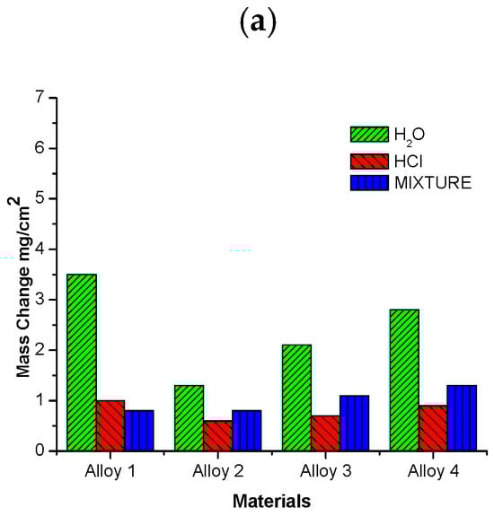
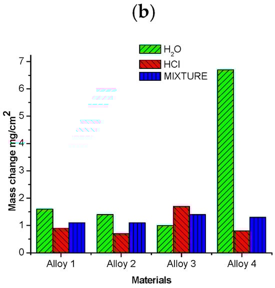
Figure 13.
Mass change of alloys investigated after 300 h of exposure at (a) 500 °C and (b) 600 °C.
7. Oxide Scale Characterization
Figure 14 illustrates how the samples were enclosed in a bakelite mold. The perimetral sides were preferentially attacked and are shown in Figure 15a–l. These micrographs were taken using a scanning electron microscope (SEM).
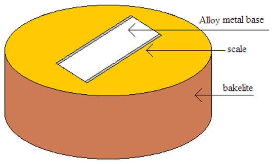
Figure 14.
A sample enclosed in bakelite showing the zone where the scale was formed.
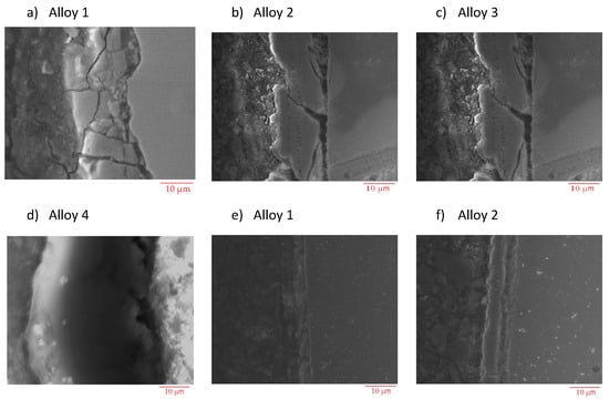
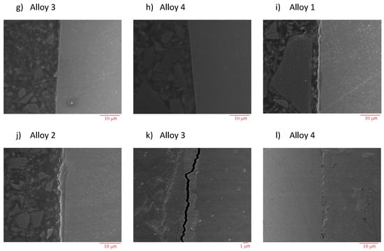
Figure 15.
Scanning electron microscopy (SEM) micrographs of metallographic cross-sections of corroded Fe-Cr specimens after 300 h of exposure to N2 containing 360 vppm H2O vapor (a–d), N2-220 vppm HCl (e–h), and N2-220 vppm HCl and 360 ppm H2O vapor (i–l) at 600 °C.
The oxide scales formed over the four alloys surfaces for all the aggressive environments at 600 °C are shown in Figure 15a–l. Figure 15a–d correspond to the alloys under the N2-360 vppm H2O atmosphere. Here, a thick scale can be observed; unfortunately, the oxides formed were not protective and the mass change continued to increase the corrosion phenomena. Figure 15e–h correspond to the samples under N2-220 vppm HCl and Figure 15i–l represent the samples under the mixed atmosphere. In all of these photographs, the scale formed is very thin and barely observable in many places. Large cracks formed in the oxide scales are observed in the interface between the scale and the metal base in Figure 15a,b; these are due to scale fragmentation. Elemental EDS maps reveal the high intensities of chromium oxides and iron along the scale. In the case of the water vapor atmosphere, the average size of the scales is about 15 µm; however, in some cases, scales were not formed. In the HCl atmosphere, the oxide scale thickness is about 5 µm.
Additionally, Figure 16a–i show the quantity of each element; the micrographs display part of the sample with the content of every element as a function of the oxide scale. The tallest histograms are for Fe and oxygen; the histograms for chlorine and chromium are smaller. This demonstrates that the main corrosion mechanism is oxidation and that it is not ruled by chlorine formation.
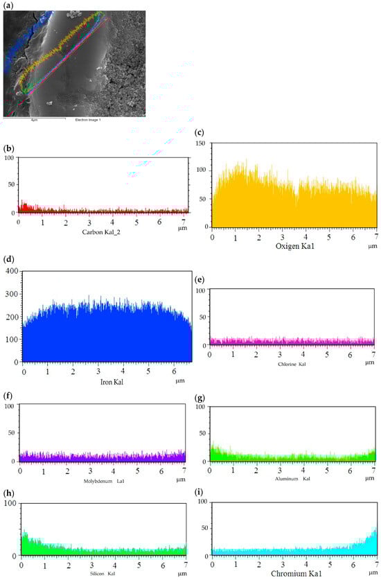
Figure 16.
Analysis of chemical composition of sample exposed to water vapor: (a) sample area; (b–i) elements found in sample.
8. Analysis of Chemical Reaction and Corresponding Results
8.1. Effect of HCl Atmosphere
In this section, the chemical equations that rule the corrosion process are presented with the purpose of understanding the underlying phenomena. Studies by Abels and others demonstrated that Cl2, rather than HCl, is the main species that promotes corrosion during very short exposure periods [19,20,21,22,23,30,31,32,34,38,39]. In oxidizing atmospheres, chlorine is formed by the reaction of HCl (Deacon Process) on top of the oxide scale present on the oxidized metal chlorides, or by reaction with the solid oxide scale [16,17,18,25,30,31,32,34,38]. This is the first phase of the active oxidation mechanism, as indicated in the chemical reaction expressed in Equation (1). Here, the HCl is decomposed to form Cl2 and an excess of water. Experimentally, the simulated system was enclosed inside the furnace but the presence of O2 can be attributed to the air remaining inside real waste incinerators. Cl2 subsequently forms metallic chlorides which will serve as intermediate products.
4 HCl (g) + O2 (g) → 2Cl2 (g) + 2H2O (g)
The chemical reaction continues due to the exposition of the base metal and the corrosive environment with some of the reactants initially formed. This process is due to the diffusion of chlorine through cracks and pores in the oxide scale on the interface metal/oxide scale [18,25,26,27,35,36,38,39,40,41,42]. The last part of the metal chloride formation is CrCl2, FeCl2, and iron-based alloys, which are developed according to the following reactions:
Fe + Cl2 → FeCl2
Cr + Cl2 → CrCl2
At temperatures of 500 °C and higher, the vapor pressures of metal chlorides are significant and volatile, promoting the chemical reactions in Equations (4) and (5).
FeCl2 (s) → FeCl2 (g)
CrCl2 (s) → CrCl2 (g)
Both FeCl2 and CrCl2 are formed steadily. In addition, at vapor pressures exceeding 10−4 atm [8,17,20,33], the metal chlorides are diffused outwards and then converted into Fe2O3 and Cr2O3, which precipitate T sites with sufficiently high oxygen pressure within the scale according to the reactions expressed in the following [21,30,31,32,34,41,42,43,44]:
4CrCl2 + 3O2 → 2Cr2O3 + 4Cl2
4FeCl2 + 3O2 → 2Fe2O3 + 4Cl2
Thus, the oxide scale formed is quite porous and may offer a weak level of protection, suggesting that the corrosion rate will be enhanced [15,16,17,18,21,22,23,25,26,27,28,29,33,35,36,37]. Furthermore, on the basis of the equilibrium oxygen partial pressures for the reaction of gaseous chlorides to solid oxides and the critical oxygen partial pressure for FeCl2, CrCl2 becomes Fe2O3, and Cr2O3 stands out [2,27,33,35,36,37,41,42,43,44,45]. Therefore, during active oxidation, the formation of chlorides, and the conversion of chlorides to oxides, pores are not formed in oxide scales. Consequently, O2 and Cl2 penetrate and react inside with the substrate and the inner scale of Cr2O3, resulting in the enrichment zone near the substrate surface being repeatedly generated [15,21,22,23,28,29,30,31,32,33].
The corrosion mechanism is described as follows: O2 and Cl2 diffuse first to form metal chlorides through the oxide scale of Cr2O3 and Fe2O3, which are subsequently deposited on the oxide scale. These Fe chlorides are isolated from the corrosive atmosphere as they remain under the oxide scale as primary formed products. In addition to the compounds formed in the HCl atmosphere, Fe and Cr are also identified, and this indicates that the scale is not thick enough; furthermore, the XRD analysis reinforces their presence as the X-rays pass through the oxide scale. The phenomenon of scale loss can be attributed to the volatility of the compounds formed.
8.2. Effect of H2O Atmosphere
The presence of water vapor during high-temperature oxidation of Fe-Cr Alloys has been the subject of many studies [15,16,23,28,29,30,31,33]. It has been shown that the mixture is highly corrosive (H2O/O2) of this group of alloys in comparison with O2. The hypotheses can be classified according to the proposed functions of water as follows:
- (1)
- Increasing the mass transport of oxygen through iron oxide.
- (2)
- Forming iron hydroxide, leading to increased mass transport of iron through the scale.
- (3)
- Increasing the diffusion rate of chromium through chromium oxide (or through a Cr-rich oxide).
- (4)
- Causing the vaporization of chromium oxide and hydroxides [15,17,18,20,21,22,23,25,26,27,35,36,37].
These hypotheses for ferritic alloys may explain why iron and other iron oxide-formers are quickly oxidized in the presence of water vapor. However, the reason why water vapor causes the non-protective properties of chromia-forming Fe-Cr to deteriorate has not been well explained.
H2O was considered the most aggressive atmosphere due to the major mass change observed for all of the alloys under this atmosphere, with the exception of alloy 3 at 600 °C. The scale of this alloy was homogeneous, as can be observed on the micrographs. Chromium and iron oxides were found in the XRD analysis, but these were not protective. Furthermore, major mass losses were measured at 600 °C; thus, it is possible to affirm that the increment in the temperature also increases the corrosion phenomena.
Studies conducted by H. Asteman [27,35,36,37,39,40,41,42,43] concluded that the vaporizing species are chromium (VI) and CrO2(OH)2 (g) as chromium oxide remains in contact with oxygen and water vapor according to the reaction expressed in Equation (8), producing gaseous chromium hydroxide. This hydroxide leaks out, thinning the protective scale.
½ Cr2O3 + ¾ O2 (g) + H2O → CrO2(OH)2
Finally, Fe and Cr oxides are deposited over the metal substrate as a result of its own reaction with humidity, forming an interface according to Equations (9) and (10). Cr2O3 is protective and very hard, whereas Fe2O3 is a weak, non-protective oxide in bulk. This explains why the results indicate a major mass change in comparison with the scenario containing HCl [28]. Here, (Fe) and (Cr) are activated directly on the sample surface as they are in contact with the aggressive atmosphere.
2Fe + 3 H2O → Fe2O3 + 3H2
2Cr + 3 H2O → Cr2O3 + 3H2 (g)
8.3. Effect of Mixture of HCl and H2O Atmosphere
The experimental results show that the simulated atmosphere containing the mixture of H2O and HCl was not as aggressive as the other atmospheres. The most aggressive mechanisms occurred when only H2O was present; corrosion was prone to occur due to the formation of hydroxides and their subsequent vaporization, as well as the formation of Fe and Cr oxides. This results from the fact that the oxides which were formed did not have protective features. In comparison, the atmospheres with HCl and the mixture (HCl-H2O) show similar behaviors, evidencing moderate influences over the corrosion mechanisms. Furthermore, in the HCl atmosphere, the mass loss was lower in comparison with that in the H2O atmosphere. Although additional reactants were found in the DXR analysis, and the chemical reactions became more complex, their influence was considerably less. Moreover, the sanding lines can be observed in the micrographs, evidencing again that the oxide scale was not protective enough.
9. Phase Stability Diagrams
Phase stability diagrams were built at 500 °C and 600 °C for the corresponding systems: Fe-Cl2-O2 and Cr-Cl2-O2. These diagrams were obtained using FACT-Stage and are shown in Figure 17, Figure 18, Figure 19 and Figure 20. The diagrams for chromium–chloride show that the product most prone to formation was Cr2O3(s), and for iron–chloride, it was Fe2O3(s). This simulation confirmed the theoretical evolution of the corrosion mechanism described in Equations (1)–(7).
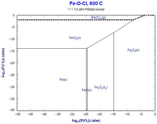
Figure 17.
Superimposed stability diagram of system (Fe-O-Cl) with solid lines at lines at 600 °C.
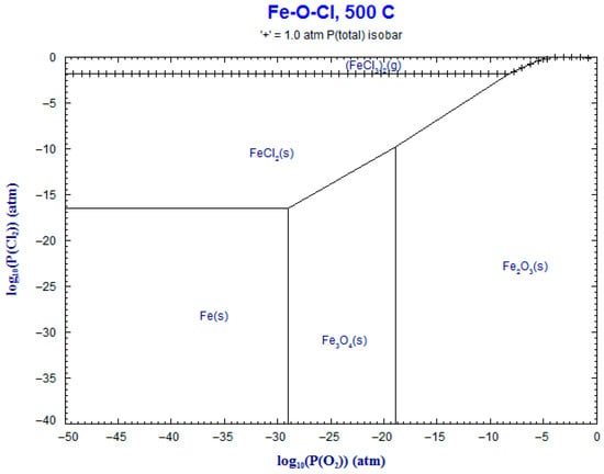
Figure 18.
Superimposed stability diagram of system (Fe-O-Cl) with solid lines at lines at 500 °C.
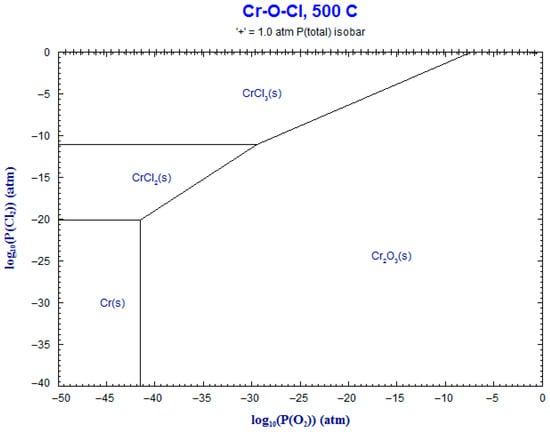
Figure 19.
Superimposed stability diagram of system (Cr-O-Cl) with solid lines at lines at 500 °C.
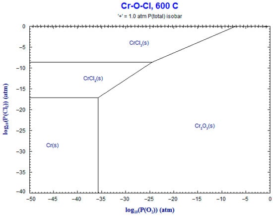
Figure 20.
Superimposed stability diagram of system (Cr-O-Cl) with solid lines at lines at 600 °C.
The calculation of the Gibbs free energy using the FACT-Stage program is shown in Table 2; here, the reaction of CrCl2 has the most negative ΔG, followed by FeCl2. Thus, these are the most probable products to be formed due to the presence of oxygen in the environment outside the furnace. Note that, inside this atmosphere, the oxide scale formed is entirely porous; moreover, the presence of flakes can be observed in Figure 6d, evidencing partial oxide formation.
Table 2.
Formation reactions and Gibbs free energy changes.
According to the values in Table 2, the reactions of Fe and Cr with H2O are more likely to occur. Furthermore, the calculations show that the increment in temperature also increases the Gibbs free energy, which can be observed in all of the micrographs shown previously. In Figure 5d, we can see a homogeneous scale and the formation of whiskers. The presence of Fe, O and Cr is confirmed through surface mapping and XRD analysis applied for characterization. Moreover, the size of the scale was measured over the micrographs in Figure 15a–l, resulting in a thickness of 15 µm. Figure 15a–d demonstrate that these have thicker scale areas, with Figure 15d showing the widest area; in contrast, the rest of the figures are narrow. Finally, in the mixed atmosphere of H2O and HCl, the presence of additional oxides can be observed at the end of the XRD analysis. Here, the oxide scale is also not homogeneous.
Although H+ is formed as a result of an incomplete or alternative chemical reaction due to the presence of H2O and HCl, as per the equations in Table 2, there is no physical evidence of its presence or any hydration or hydrogen embrittlement damage inside the samples. We propose that an additional experiment over longer exposure periods could prove this fact. Moreover, we found no other additional chemical compound based on hydrogen in the X-ray analysis. FACT-Stage software did not calculate the formation of any additional compound.
10. Conclusions
Different oxide morphologies were obtained for the scales formed as a function of the corrosion conditions and alloy composition. A thicker heterogeneous oxide scale was formed in the H2O atmosphere due to major mass change.
Fe-Cr alloys react with water vapor and HCl, forming oxide scales, mainly Cr2O3 and Fe2O3, but they also form (Fe0.6Cr0.4)2O3 in water vapor atmospheres. The formation of the first two oxides suggests that active oxidation occurs mainly from chlorine, as proposed by H.T. Ma. et al. [25]. On the other hand, inside the mixed and HCl atmospheres, a non-homogeneous scale made of a very thin oxide was observed, demonstrating a moderate corrosion attack. Furthermore, the alloy bases (Fe) and (Cr) can be found in the XRD patterns.
Additionally, the presence of CrSiO4, (Cr, Fe)2O3, and FeCr2O4 was observed using XRD analysis, but its influence was not studied. The assumptions regarding corrosion evolution were validated in using the software FACT-Stage and the chemical equations that describe the most probable corrosion mechanism.
According to the mass change analysis, the alloy with the best performance averaged across the three environments was alloy 2. The most aggressive environment was the water vapor atmosphere at 600 °C.
Alloy 4 contains Al and Si; nevertheless, the influence of these elements was not considered to be significant in terms of conferring better performance because the increase in the quantity of these elements was not enough to provoke notorious improvement.
The chlorides formed during the evolution of corrosion are intermediate products, whereas the oxides were formed at the end of the process. However, these oxides were not protective, and consequently, the alloys were not passive.
According to the results obtained, it appears that the interaction between the HCl atmosphere and the metal base was minor compared to that in H2O and the mixed atmosphere; as such, we can conclude that these are less aggressive environments.
It is well known that HCl is a very aggressive environment and attacks stainless steel. Nevertheless, the alloys in the present study have a low content of chromium, which may be the reason why the H2O environment was found to be the most aggressive.
The purpose of this work was to prove that some ferrous alloys with 9% Cr and other additional elements can resist corrosion inside a waste incinerator; nevertheless, it is difficult to fully elucidate the influence of every alloy element on the improvement in corrosion resistance as the variations were so low. To understand the influence of every element, we recommend significantly increasing the content of each element in the analyzed alloy and verifying the alloys’ resistance against corrosion according to the phases and compounds formed. It is evident that the composition of the atmosphere strongly influences the corrosion mechanism transforming chlorines to oxides and vice versa.
The corrosion process became parabolic, revealing that the four alloys are passive over long exposure durations, suggesting that they are appropriate for use as wall materials in waste incinerators, although it should be noted that the chemical composition of burned waste can affect their lifetime.
Author Contributions
All authors worked on the experiments of the four alloys and casting; all authors were involved in preparing the experimental set-up and helped to control the process; moreover, all authors together worked on the characterization of scales and materials using SEM and XRD analysis; finally, all authors contributed to writing each section of the manuscript and analyzing the evidences to provide conclusions. All authors have read and agreed to the published version of the manuscript.
Funding
This research received no external funding.
Data Availability Statement
The original contributions presented in this study are included in the article. Further inquiries can be directed to the corresponding author(s).
Acknowledgments
The authors wish to express their gratitude to their institutions, National Polytechnic Institute (IPN), The Autonomous and Technological institute of Mexico (ITAM,) and The National Council for Humanities Science and Technology (CONAHCyT), for their technical support.
Conflicts of Interest
The authors declare no conflicts of interest.
References
- Pint, B.A.; Wright, I.G. Oxidation Behavior of ODS Fe–Cr Alloys. Oxid. Met. 2005, 63, 193–213. [Google Scholar] [CrossRef]
- Zahs, A.; Spiegel, M.; Grabke, H. The influence of alloying elements on the chlorine-induced high temperature corrosion of Fe-Cr alloys in oxidizing atmospheres. Mater. Corros. 1999, 50, 561–578. [Google Scholar] [CrossRef]
- Zahs, A.; Spiegel, M.; Grabke, H.J. Chloridation and oxidation of iron, chromium, nickel and their alloys in chloridizing and oxidizing atmospheres at 400–700 °C, Corrosion. Science 2000, 42, 1093–1122. [Google Scholar] [CrossRef]
- Spiegel, M. Salt melt induced corrosion of metallic materials in waste incineration plants. Mater. Corros. 1999, 50, 373–393. [Google Scholar] [CrossRef]
- Frandsen, F.J. Utilizing biomass and waste for power production—A decade of contributing to the understanding, interpretation and analysis of deposits and corrosion products. Fuel 2005, 84, 1277–1294. [Google Scholar] [CrossRef]
- Persson, K.; Broström, M.; Carlsson, J.; Nordin, A.; Backman, R. High Temperature Corrosion in a 65 MW Waste to Energy Plant. Fuel Process. Technol. 2007, 88, 1178–1182. [Google Scholar] [CrossRef]
- Srikanth, S.; Ravikumar, B.; Das, S.K.; Gopalakrishna, K.; Nandakumar, K.; Vijayan, P. Analysis of failures in boiler tubes due to fireside corrosion in a waste heat recovery boiler. Eng. Fail. Anal. 2003, 10, 59–66. [Google Scholar] [CrossRef]
- Streiff, R.; Stringer, J.; Krutenat, R.C.; Caillet, M. (Eds.) High Temperature Corrosion of Materials and Coatings for Energy Systems and Turboengines; Elsevier Sequoia: Lausanne, Switzerland, 1987. [Google Scholar]
- Streiff, R.; Stringer, J.; Krutenat, R.C.; Caillet, M. (Eds.) High Temperature Corrosion and Protection of Materials; Les Éditions de Physique: Les Ulis, France, 1993; Volume 3. [Google Scholar]
- Streiff, R.; Stringer, J.; Krutenat, R.C.; Caillet, M. (Eds.) High Temperature Corrosion: Advanced Materials and Coatings; Elsevier: London, UK, 1989; Volume 2. [Google Scholar]
- Ihara, Y.; Ohgame, H.; Sakiyama, K.; Hashimoto, K. The corrosion behaviour of iron in hydrogen chloride gas and gas mixtures of hydrogen chloride and oxygen at high temperatures. Corros. Sci. 1981, 21, 805–817. [Google Scholar] [CrossRef]
- Ihara, Y.; Ohgame, H.; Sakiyama, K.; Hashimoto, K. The corrosion behavior of chromium in hydrogen chloride gas and gas mixtures of hydrogen chloride and oxygen at high temperatures. Corros. Sci. 1983, 23, 167–181. [Google Scholar] [CrossRef]
- Jacobsen, N.S. Reaction of iron with Hydrogen Chloride-Oxygen Mixtures at 550 °C. Oxid. Met. 1986, 26, 157–169. [Google Scholar] [CrossRef]
- Stott, F.H.; Prescott, R.; Elliott, P. The Corrosion of metals in an oxidizing-chloridizing environment at high temperature. Werk. Korros. 1988, 39, 401. [Google Scholar] [CrossRef]
- Abels, J.M.; Strehblow, H.H. A surface analytical approach to the high temperature chlorination behaviour of inconel 600 at 700 °C. Corros. Sci. 1997, 39, 115–132. [Google Scholar] [CrossRef]
- Fontana, M.G.; Staehle, R.W. Advances in Corrosion Science and Technology; Springer: Berlin/Heidelberg, Germany, 1976; Volume 6. [Google Scholar]
- Kubaschewski, O.; Hopkins, B.E. Oxidation of Metals and Alloys; Butterworths: London, UK, 1967. [Google Scholar]
- Lu, W.M.; Pan, T.J.; Zhang, K.; Niu, Y. Accelerated corrosion of five commercial steels under a ZnCl2–KCl deposit in a reducing environment typical of waste gasification at 673–773 K. Corros. Sci. 2008, 50, 1900–1906. [Google Scholar] [CrossRef]
- Strafford, K.; Datta, P.; Forster, G. High-temperature chloridation of binary FeCr alloys at 1000 °C. J. MSE-A 1989, 120–121, 61–68. [Google Scholar]
- Shinata, Y.; Hara, M.; Nakagawa, T. Accelerated oxidation of chromium by trace of sodium chloride vapor. Mater. Trans. JIM 1991, 32, 969–972. [Google Scholar] [CrossRef]
- Simms, N.; Seraffon, M.; Pidcock, A.; Davis, C. Assessment of Coating Performance on Waterwalls and Superheaters in a Pulverised Fuel-Fired Power Station. Oxid. Met. 2017, 88, 165–177. [Google Scholar] [CrossRef]
- Jonsson, T.; Karlsson, S.; Hooshyar, H.; Sattari, M.; Liske, J.; Svensson, J.-E.; Johansson, L.-G. Oxidation After Breakdown of the Chromium-Rich Scale on Stainless Steels at High Temperature: Internal Oxidation. Oxid. Met. 2016, 85, 509–536. [Google Scholar] [CrossRef]
- Pastén, M.S.; Spiegel, M. High temperature corrosion of metallic materials in simulated waste incineration environments at 300–600 °C. Mater. Corros. 2006, 57, 192–195. [Google Scholar] [CrossRef]
- Lee, S.Y.; McNallan, M.J. Inhibition of Oxidation of Iron in Environments Containing Chlorine at 1100 and 1200 K. J. Electrochem. Soc. 1990, 137, 472–479. [Google Scholar] [CrossRef]
- Ma, H.T.; Zhou, C.H.; Wang, L. High temperature corrosion of pure Fe, Cr and Fe–Cr binary alloys in O2 containing trace KCl vapour at 750 °C. Corros. Sci. 2009, 51, 1861–1867. [Google Scholar] [CrossRef]
- Kofstad, P. High-Temperature Corrosion; Elsevier Applied Science: London, UK, 1988; Chapter 11; pp. 382–385. [Google Scholar]
- Caplan, D.; Cohen, M. The volatilization of chromium oxide. J. Electrochem. Soc. 1961, 108, 438. [Google Scholar] [CrossRef]
- Asteman, H.; Svensson, J.-E.; Norell, M.; Johansson, L.-G. Influence of Water Vapor and Flow Rate on the High-Temperature Oxidation of 304L; Effect of Chromium Oxide Hydroxide Evaporation. Oxid. Met. 2000, 54, 11–26. [Google Scholar] [CrossRef]
- Asteman, H.; Svensson, J.E.; Johansson, L.G. Evidence for Chromium Evaporation Influencing the Oxidation of 304L: The Effect of Temperature and Flow Rate. Oxid. Met. 2002, 57, 193–216. [Google Scholar] [CrossRef]
- Asteman, H.; Svensson, J.E. Oxidation of 310 steel in H2O/O2 mixtures at 600 °C: The effect of water-vapor-enhanced chromium evaporation. Corros. Sci. 2002, 44, 2635–2649. [Google Scholar] [CrossRef]
- Alcántara-Cárdenas, J.A.; Ramirez-Lopez, A.; Chávez-Alcalá, J.F.; Sanchez-Pastén, M. Evaluation of High Temperature Corrosion in Simulated Waste Incinerator Environments. Oxid. Met. 2016, 85, 611–627. [Google Scholar] [CrossRef]
- Segerdahl, K.; Svensson, J.-E.; Johansson, L.-G. The high temperature oxidation of 11% chromium steel: Part I—Influence of pH2O. J. Mater. Corros. 2002, 53, 247–255. [Google Scholar] [CrossRef]
- Asteman, H.; Svensson, J.-E.; Johansson, L.-G.; Norell, M. Indication of Chromium Oxide Hydroxide Evaporation During Oxidation of 304L at 873 K in the Presence of 10% Water Vapor. Oxid. Met. 1999, 52, 95–111. [Google Scholar] [CrossRef]
- Sequeira, C.A.C. Chapter, 20. High-Temperature Oxidation. In Uhlig’s Corrosion Handbook, 3rd ed.; Revie, R.W., Ed.; Wiley: Hoboken, NJ, USA, 2011. [Google Scholar] [CrossRef]
- Tedmond, C.S., Jr. The Effect of Oxide Volatilization on the Oxidation Kinetics of Cr Fe-Cr Alloys. J. Electrochem. Soc. 1966, 113, 766–768. [Google Scholar] [CrossRef]
- Rahmel, A.; Tobolski, J. Einfluss von wasserdampf und kohlendioxyd auf die oxydation von eisen in sauerstoff bei hohen temperature. Corros. Sci. 1965, 5, 333–346. [Google Scholar] [CrossRef]
- Thiele, M.; Quadakkers, W.J.; Teichmann, H.; Schwarz, W. Corrosion behaviour of ferritic and austenitic steels in simulated flue gases from bituminous and brown coal-fired power stations. VGB Kraftwerkstechnik 1997, 77. [Google Scholar]
- Caleyo, F.; Alfonso, L.; Alcántara, J.; Hallen, J.M. On the Estimation of Failure Rates of Multiple Pipeline Systems. In Proceedings of the 2006 International Pipeline Conference, Volume 3: Materials and Joining; Pipeline Automation and Measurement; Risk and Reliability, Parts A and B. Calgary, AB, Canada, 25–29 September 2006; pp. 1107–1115. [Google Scholar]
- Galerie, A. High Temperature Oxidation and Corrosion of Metals and Alloys: Fundamentals and Influence of High Energy Beams. In Application of Particle and Laser Beams in Materials Technology; Misaelides, P., Ed.; NATO ASI Series; Springer: Dordrecht, The Netherlands, 1995; Volume 283. [Google Scholar] [CrossRef]
- Taniguchi, S.; Maruyama, T.; Yoshiba, M.; Otsuka, N.; Kawahara, Y. (Eds.) High Temperature Oxidation and Corrosion 2005; Trans Tech Publications: Zürich, Switzerland, 2006. [Google Scholar]
- Steinmetz, P.; Wright, I.G.; Meier, G.; Galerie, A.; Pieraggi, B.; Podor, R. (Eds.) High Temperature Corrosion and Protection of Materials; Trans Tech Publications: Zürich, Switzerland, 2004; Volume 6. [Google Scholar]
- Birks, N.; Meier, G.H.; Pettit, F.S. Introduction to the High Temperature Oxidation of Metals; Cambridge University Press: Cambridge, UK, 2006. [Google Scholar]
- Israelsson, N.; Engkvist, J.; Hellström, K.; Halvarsson, M.; Svensson, J.-E.; Johansson, L.-G. KCl-Induced Corrosion of an FeCrAl Alloy at 600 °C in O2 + H2O Environment: The Effect of Pre-oxidation. Oxid. Met. 2015, 83, 29–53. [Google Scholar] [CrossRef]
- Israelsson, N.; Unocic, K.A.; Hellström, K.; Jonsson, T.; Norell, M.; Svensson, J.-E.; Johansson, L.-G. A Microstructural and Kinetic Investigation of the KCl-Induced Corrosion of an FeCrAl Alloy at 600 °C. Oxid. Met. 2015, 84, 105–127. [Google Scholar] [CrossRef]
- Dudziak, T.; Łukaszewicz, M.; Simms, N.; Nicholls, J. Analysis of High Temperature Steam Oxidation of Superheater Steels Used in Coal Fired Boilers. Oxid. Met. 2016, 85, 171–187. [Google Scholar] [CrossRef]
- Kawahara, Y. High temperature corrosion mechanisms and effect of alloying elements for materials used in waste incineration environment. Corros. Sci. 2002, 44, 223–245. [Google Scholar] [CrossRef]
- Kawahara, Y. Controlling Factors of Localized Corrosion in Boiler Combustion Gas Environments. Oxid. Met. 2016, 85, 127–149. [Google Scholar] [CrossRef]
- Fujikawa, H.; Maruyama, N. Corrosion behavior of austenitic stainless steels in the high chloride-containing environment. Mater. Sci. Eng. A 1989, 120–121, 301–306. [Google Scholar] [CrossRef]
- Dudziak, T.; Deodeshmukh, V.; Backert, L.; Sobczak, N.; Witkowska, M.; Ratuszek, W.; Chruściel, K.; Zieliński, A.; Sobczak, J.; Bruzda, G. Phase Investigations Under Steam Oxidation Process at 800 °C for 1000 h of Advanced Steels and Ni-Based Alloys. Oxid. Met. 2017, 87, 139–158. [Google Scholar] [CrossRef]
- Jönsson, B.; Westerlund, A. Oxidation Comparison of Alumina-Forming and Chromia-Forming Commercial Alloys at 1100 and 1200 °C. Oxid. Met. 2017, 88, 315–326. [Google Scholar] [CrossRef]
- Essuman, E.; Meier, G.H.; Żurek, J.; Hänsel, M.; Quadakkers, W.J. The Effect of Water Vapor on Selective Oxidation of Fe–Cr Alloys. Oxid. Met. 2008, 69, 143–162. [Google Scholar] [CrossRef]
- Nguyen, T.D.; Zhang, J.; Young, D.J. Water Vapor Effects on Corrosion of Fe–Cr and Fe–Cr–Ni Alloys Containing Silicon in CO2 Gas at 818 °C. Oxid. Met. 2015, 83, 575–594. [Google Scholar] [CrossRef]


Disclaimer/Publisher’s Note: The statements, opinions and data contained in all publications are solely those of the individual author(s) and contributor(s) and not of MDPI and/or the editor(s). MDPI and/or the editor(s) disclaim responsibility for any injury to people or property resulting from any ideas, methods, instructions or products referred to in the content. |
© 2025 by the authors. Licensee MDPI, Basel, Switzerland. This article is an open access article distributed under the terms and conditions of the Creative Commons Attribution (CC BY) license.