Abstract
One of the most widely used rocket propulsion systems that uses liquid propellants is the liquid rocket engine. Due to their high density and specific impulse, liquid fuels and oxidizers are preferred. This project’s goal was to evaluate the performance of a small-scale liquid rocket engine’s pressure feed system, which generates 250 N of thrust. A thrust bed was used for testing to obtain the experimental values, since rocket engine testing was required. A bipropellant chemical propulsion system that uses kerosene II as fuel and gaseous oxygen as an oxidant was created. Using NASA CEA, a theoretical performance evaluation was also performed in addition to this experimentation. For different propellant mixture ratios, the performance metrics under equilibrium flow, including specific impulse, characteristic velocity, thrust, and nozzle exit temperature, were examined. The performance parameters, characteristic velocity, and thrust were highest for all considered chamber pressure values and were maximum at a mixture ratio of 2.25.
1. Introduction
In liquid rocket engines, injection is done through tiny holes, sometimes known as “orifices”, that can be angled to allow fuel streams to transition into other fuel and oxidizer streams. This is particularly true for engines that have both propellants “liquid”, like LOX/kerosene engines. The “impingement”—the intersection of liquid streams—causes the streams to split up into a large number of tiny liquid droplets. These little droplets then burn and disappear. An “Injector” is a machine that injects oxidizer and fuel. The fuel and oxidizer must be forced into the combustion chamber to mix thoroughly, evaporate quickly, and then undergo a chemical reaction, or “burn” [1,2]. Over the last several decades of the 20th century, there was a notable advancement in liquid rocket propulsion. The commercialization of space will present both enormous opportunities and challenges in the coming century. To maximize the performance and adaptability of the engines that are now on the market, suggestions were made to enhance their memory and prediction for the development of liquid rocket propulsion [3]. The operational benefit of liquid-propellant rocket engines (LREs), referred to as on-command variable thrust or thrust modulation, has been the subject of sporadic research since the late 1930s. Planetary entry and descent, space rendezvous, orbital maneuvering (including space orientation and stability), hovering, and avoiding risks during planetary landing are among the uses for adjustable LREs. Other uses have included monitoring airplane rocket engines, employing retrograde rockets to reduce vehicle acceleration or velocity, and regulating the trajectory of ballistic missile defenses. Additionally, unlike discrete throttling changes over a few chosen operating points, throttle-able LREs can continually follow the most cost-effective thrust curve in a particular scenario. The throttling behaviors are important and include the impact of altering thrust on the dynamics and mechanics of an LRE as well as challenges and problems with the throttling process itself. With an emphasis on engines, this paper offers a thorough analysis of LRE throttling [4]. The primary technological component that has made human space exploration possible is the rocket engine. The development of the rocket engine has relied heavily on the turbo pump system, due to evolving needs and technological breakthroughs. Apart from showcasing some of the most significant engines in human history, this paper offers details on the technological advancements of the past century. This paper provides a comparative analysis of the many turbo pump configurations and a road map for comprehending the several types of turbo pump systems seen in liquid propulsion rocket engines. This page also provides an overview of the turbo pump and the numerous works that have been done on it and connected to this business over the years, which will be helpful to both novice and experienced researchers [5]. The aircraft industry makes extensive use of liquid rocket engines due to their remarkable controllability. Designing, building, and testing a small liquid rocket engine with kerosene and gaseous oxygen was the goal of this project. The engine was built to handle a 20 bar chamber pressure. Nevertheless, during combustion, the engine could sustain a chamber pressure of up to 30 bar, which was higher than the maximum chamber pressure of 20 bar. Engine cold flow tests were conducted at chamber pressures of 4, 6, 8, and 10 bar. Following a successful conclusion, two samples were tested for simultaneous hot flow. The first feeding of the fuel and oxidizer resulted in a combustion chamber pressure of about 9 bar. Later, to increase the chamber pressure to 12.5 bar for the second test, the fuel and oxidizer feed pressures were increased simultaneously. This paper includes a detailed analysis and tabulation of each test result for each incident [6]. The goal of this technology development procedure was to increase the degree of technological preparedness for installation on existing liquid rocket engines by taking into account every design and manufacturing phase, including material characterization, updating the design tools as needed, and performing basic single-element screening tests prior to developing, producing, and fire testing several injector configurations. The research initiatives also seek to optimize the possibilities of additive manufacturing for liquid rocket engines in the future. A more thorough approach can be performed without the need for additional certification and justification work because the design is not yet completed [7]. The space launch system for crew exploration outside of low Earth orbit was developed by NASA. The Marshall Space Flight Center (MSFC) created a rocket engine. For the engine to run steadily, the injector must function at a high level. Some instability was displayed by the combo, which must be a major issue for this kind of injector design. They used the computational fluid dynamics (CFD) program to address this problem. The combustion, fuel mixture, and oxidizer comprise the thrust chamber assembly. Among the simulation’s results are temperature, pressure, predictions, and combustion metrics that show [8]. German Aerospace created the liquid rocket engine injector for a state-of-the-art launcher for Europe. This injector is part of the liquid oxygen/kerosene engine. One type of injector is a coaxial injector. The material used to 3D print this injector is PLA. Furthermore, a film/laying capability built into the created injector allows the engineer to directly alter the film’s mass flow rate to the injector. Materials made of ceramic are used to resist the heat. A top-quality liquid fuel injector atomizes and blends fuel and oxidizer to provide the required thrust [9]. A huge volume of fuel and oxidizer combination is pumped into the Formula One engine’s combustion chamber by the injector plate. The injector is inserted right before the LOX dot. The injector and Ox dome are connected by bolts, and they are subsequently fastened to the thrust chamber. The orifice arrangement is set up in a pair so that the fuel mixture and oxidizer are ejected through the impinging points in a similar doublet pattern. The fuel and oxidizer vapors mix, burn, and expel hot gases through the nozzle at impinging jets. The determined combustion may be achieved by modifying the impediment angle and the orifice plate diameter. The second injector uses baffles on the injector’s face [10]. The concept of combustion instability in liquid propellant rocket engines is difficult for humans to comprehend and forecast because of the complicated turbulence process. Conventional techniques have increased the system’s damping by removing combustion instabilities. These approaches typically have flaws, because the underlying mechanisms have not been well investigated. Among the phenomena that have posed challenges are the creation of sprays, turbulence in multiphase flow settings, injection hydrodynamics, and droplet transport properties. Preventing the emergence of combustion instability and guaranteeing dependable operation throughout the whole combustion process are the ultimate goals of engine design. This article provides thorough advice on how to prevent the several types of combustion instabilities that might arise in rocket engines driven by liquid propellants [11]. The dual-manifold injector’s design maintains sufficient injector pressure. Other names for this injector include dual circuit, dual orifice, and two-stage. This injector’s modest thrust improves performance and stability at larger pressure drops. Dissipative injectors in hydrodynamics operate using dynamic fluid techniques. Raising the injector velocity can enhance performance efficiency at low thrust levels, resulting in adequate stability and acceptable performance. Consent refers to the dual manifold located at the liquid/oxidizer side, where the transition between operational stability and combustion stability occurs [12]. This prediction pertains to the impingement spray conditions in the combustion chamber. The traditional, rather than uncoupled, spray model of an injector incorporating the dual connection of jet impingement testing with the ambient gas field was studied. Compared to the uncoupled model, the more practical impingement spray specifications can simulate the coupling spray and combustion system of a liquid rocket engine [13]. We analyzed the performance of an underdeveloped L75 liquid rocket engine using LOX/ethanol with various liquid rocket engine configurations. Here, we use the unified modeling tool—the study of design parameters that affect the performance and the dry mass of the L75 liquid rocket engine—to model the architecture of the codes [14]. The study outlines a methodology for modeling and stability analysis. The different physical processes at a nominal regime and the components of the liquid rocket engine were linearly modeled [15].
2. Methodology
The objective of our project was to evaluate the performance parameters of a liquid rocket engine such as thrust, specific impulse, characteristic velocity, and exit nozzle temperature for a liquid propellant combination of kerosene and oxygen at different mixture ratios and chamber pressure conditions. The methodology included the following:
- Design and fabrication of Liquid Rocket Engine components
- Development of a test setup
- Experimental testing of the engine using liquid fuel kerosene and gaseous oxygen
- Theoretical performance analysis of the engine done in NASA CEA
2.1. Simulation Using NASA-CEA Program
The NASA CEA (Chemical Equilibrium with Applications) computer program is widely used in calculating complex mixtures’ chemical equilibrium compositions and properties. The software includes assigned thermodynamics Using the NASA CEA software, the analysis of all significant outcomes of the liquid rocket engine has been achieved, and the built-in software calculations of the rocket’s performance.
2.2. Propellant Selection
The design of the liquid rocket engine started with the selection of liquid fuel and liquid oxidizer (Table 1).

Table 1.
Properties of Propellant.
- ➢
- Fuel: 2nd-grade kerosene (C15H32)
- ➢
- Oxidizer: gaseous oxygen (O2)
2.3. Design and Fabrication of Engine Components
2.3.1. Injector and Combustion Chamber Design
The design of the injector is shown in Table 2. The combustor’s geometry (spherical or cylindrical) can partially affect the rate of combustion and the injector’s geometry. Fora short chamber length, it will reduce the combustion efficiency. A smaller diameter and sufficiently long combustor help provide adequate turbulence for mixing and atomizing the mixture, which causes good combustion stability. The operating and design parameters are given in Table 3 and Table 4.
Table 2.
Injector Design Parameters.
Table 3.
Combustion Chamber Operating Parameters.
Table 4.
Combustion Chamber Design Parameters.
2.3.2. Nozzle Design
The nozzle to be designed is a convergent-divergent nozzle for the liquid rocket engine. Mass flow rate can determine the capacity of a rocket engine through the nozzle exit, along with the exit velocity and pressure. The cross-sectional area of the nozzle influences these parameters. Converging-diverging (CD) nozzles are among the most commonly used and efficient nozzles (shown in Table 5).
Table 5.
Nozzle Design Parameters.
3. Experimental Setup and Testing
3.1. Liquid Rocket Engine Test Setup
The schematic given below describes the overall setup of the liquid rocket motor, along with its components and other instruments required for conducting the testing (Figure 1). A pressure-fed system was used to feed the propellant to flow (Table 6). A convergent-divergent nozzle was used, designed, and fabricated according to the dimensions of the combustion chamber and attached next to the chamber. All of the parts mentioned above were made of stainless steel.
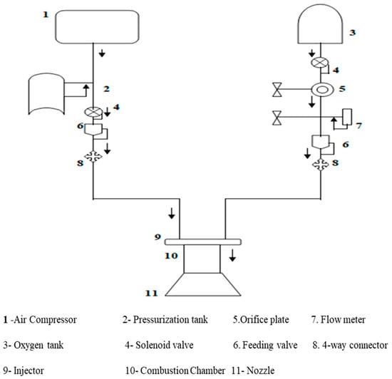
Figure 1.
Schematic Layout of the Test Setup.
Table 6.
Properties of Product Gas.
A pressure regulator was connected to the oxygen cylinder using a 10,000 psi, 3-m-long hosepipe connected to the oxygen mass flow meter and the orifice plate. A solenoid valve was connected to control the flow of oxygen. On the other end, an air compressor was used to compress and pressurize the fuel to flow into the injector, which was connected using a hose pipe and an orifice plate to the inlet of the chamber.
The ignition system was a part of the experimental setup used for igniting the fuel grain during testing. It comprised an igniter, nichrome wire, connecting wire, and control power supply. Nichrome wire was wrapped around the igniter and further connected to the power supply through the connecting wire. The control power supply varied the voltage in the circuit. The igniter was placed inside the fuel grain through the nozzle. Two pressure transducers were attached upstream and downstream of the orifice plate to measure the pressure difference. One more pressure transducer was attached at a location of the chamber to measure the combustion pressure. A K-type thermocouple was attached at the nozzle exit of the setup. A load cell of 40 kg capacity was attached to measure the static thrust (Figure 2).
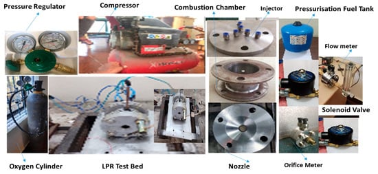
Figure 2.
Experimental Setup.
3.2. Operating Procedure
In the fuel tank, the air was compressed at 4 bar pressure and the fuel was allowed to flow into the injector. The fuel flow rate was obtained using Arduino. Oxygen was allowed to flow from the oxygen cylinder at an injection pressure of 6 bar using a pressure regulator to the unlike doublet injector. The flow rate of oxygen was calculated using the traditional weighing method (errors in the observation of the oxygen flow rate were measured using an orifice meter). Two pressure transducers were used to measure the pressure difference attached to the orifice plate at two locations. A solenoid valve attached to the fuel and oxidizer supply system was used to control the flow of fuel and oxygen. The fuel and oxygen were then allowed to mix in the combustion chamber, and ignition was started by an igniter connected by nichrome wire placed at a location inside the chamber through the nozzle, which is connected to the injector box. As the igniter burned, combustion occured in the chamber, and the flame/ hot exhaust gas was released through a nozzle. The observations were chamber pressure, thrust as measured by a pressure transducer, and load cell measurements.
4. Results and Discussion
A small-scale liquid rocket engine with the thrust bed setup was entrenched, and the main objective and purpose were achieved. A synopsis of different approaches, including all significant factors of the propulsion system, the propellant used, types of fuels, software, fabrication of the designed components, assumptions, calculations for the engine, and pre-testing in a safe and effective manner has been presented. With the use of the NASA CEA software, the analysis of all significant outcomes of the liquid rocket engines has been achieved.
- Pre-testing of Liquid Rocket Engine
4.1. Air Compressor Testing
The pressurized air was filled into the pressure tank using an air compressor. The bladder in the tank was filled with water. The injection pressure was set at 4 bar. This process was carried out to inspect whether the indicator located on the air compressor was functioning properly.
4.2. Injector Testing
The injector is the most important component of a rocket engine. It determines and affects the efficiency of the entire thrust engine based on atomization.
The unlike doublet injector was tested using water and oxygen pumping through their respective injector holes to check whether the atomization was proper or not. The flow rates of water and oxygen were also found during this testing (Figure 3). The flow rate of water was 0.02 kg/min and the flow rate of oxygen was 0.3 kg/min (Table 7).
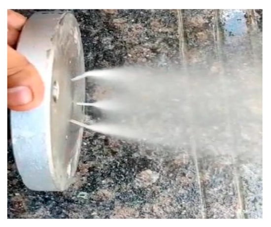
Figure 3.
Injector Testing.
Table 7.
Operating Conditions.
4.3. Mass Flow Rate Testing of Oxygen
To measure the mass flow rate of oxygen gas, an orifice meter was used. However, it was not working, and there was too much deviation between the upstream and downstream values. The conventional method was used to measure the mass flow rate, using the weighing machine. The initial and final value weights of the oxygen were noted down for a test duration of 30 s at an injection pressure of 6 bar (Table 8).
Table 8.
Rate of Change of Mass Flow of Oxygen.
4.4. Igniter Testing
The prepared igniter was burned using an electric supply for 3 s. A nichrome wire of 0.25 mm diameter was connected to the igniter box. After the pre-testing of the different components, the sample combustion test was carried out in the following operating conditions.
4.5. Load Cell Calibration
The load cell was calibrated by applying a known weight on the load cell connected to an HX711 driver using software. The tare and the scale factor were set by the software, and the continuous data acquisition plots were verified to check whether the thrust values were plotted according to the force exerted on the load cell.
4.6. Experimental Results
4.6.1. Chamber Pressure Variation with Time
Between 0 and 20 s of fuel burn, pressure readings within the combustion chamber were meticulously tracked and documented. The critical phases of the motor test firing—the ramp-up, steady state, and cut-off stages—were closely observed as depicted in Figure 4. There was a slight decline in chamber pressure throughout firing, which became more pronounced with higher oxidizer mass flow rates.
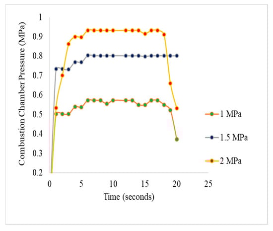
Figure 4.
Chamber Pressure Variation with Time.
The initial ignition of the engine showed a noticeable pressure surge, attributed to the primer charge igniting and releasing significant heat and combustion gases upon activation of the igniter. The pressure–time profile at 1.5 MPa revealed a proportional increase in burning rate alongside oxidizer mass flow and chamber pressure, marking the onset of the ramp-up phase as combustion gas expansion elevated pressure levels. During steady-state operation, changes in fuel mass flow rate altered the pressure pattern, leading to a gradual decrease in chamber pressure toward the end of the burn. These observations suggest that turbulent flame propagation speed may influence the rate of combustion chamber pressurization, with the rapid spread of flame attributed to the turbulent mixing within the engine.
4.6.2. Theoretical Performance Analysis
The theoretical analysis of different parameters of a liquid rocket engine was carried out using the NASA CEA program. The following boundaries were selected for the simulation.
- ➢
- Initial conditions were selected for simulation.
- ➢
- Fuel RP-1 (Kerosene) and oxidizer gaseous oxygen were selected.
- ➢
- The chamber pressure values were assigned in the range of 2 bar to 10 bar with an interval of 2.
- ➢
- Pressure ratio = 3.92.
- ➢
- The mixture ratio (O/F) values assigned were in the range of 1 to 5 with an interval of 1 and a stoichiometric O/F Ratio of 3.48.
- ➢
- Contraction ratio = 9 finite area combustion chamber.
The adiabatic flame temperature vs. mixture (O/F) ratio (Figure 5) delineates that the adiabatic flame temperature is rapidly increasing when the mixture (O/F) ratio is one. The critical condition was at point 3.12, where the maximum adiabatic flame temperature was achieved; after that point, it became constant until the O/F balance reached 3.94. After the critical point, the chamber temperature decreased, altering the mixture (O/F) ratio. Similar patterns were observed for the remaining chamber pressures. The maximum temperature of 3441.39 k was achieved at the critical point.
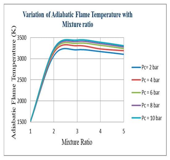
Figure 5.
Adiabatic Flame Temperature vs. Mixture (O/F).
Figure 6 shows the specific impulse of different mixture ratios (O/F). It delineates that at different chamber pressures, increasing the mixture (O/F) ratio also increases the Isp until it reaches point 2.34. At point 2.34, the value of Isp is at its maximum, which is 182.04. It then decreases for the remaining chamber pressures. Figure 7 delineates that at a mixture (O/F) ratio 2.5, the value of typical velocity is at its maximum, which is 1770 m/s. After this point, the velocity constantly decreases for all remaining chamber pressures.
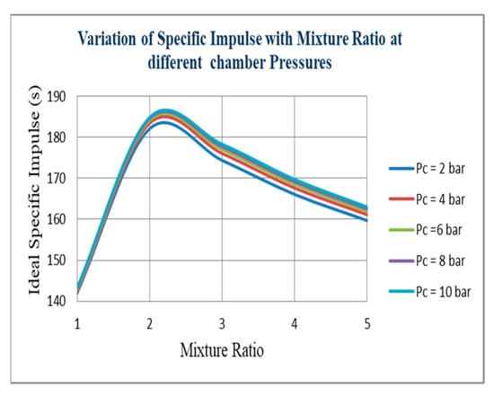
Figure 6.
Ideal Specific Impulse vs. Mixture (O/F) ratio.
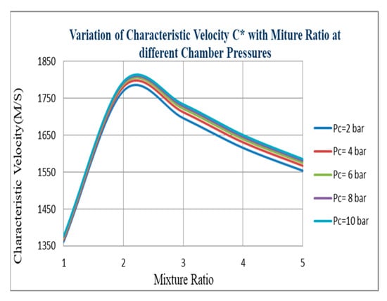
Figure 7.
Characteristic Velocity vs. Mixture (O/F) Ratio.
Figure 8 indicates that at point 3.12, the maximum exit temperature can be achieved. After that point, the nozzle exit temperature will decrease negligibly with regard to the mixture (O/F) ratio for all chamber pressure values. From Figure 9, the variations of thrust with mixture (O/F) ratio indicate that at point 2.345, the maximum thrust can be achieved. The variation of the ideal specific impulse with chamber pressure delineates that the specific impulse will increase with increasing pressure. However, the difference between two specific impulse values at chamber pressures 4 and 10 was negligible. A significant chamber pressure can affect combustion efficiency so the expected specific impulse value can be achieved at the determined chamber pressure. (Figure 10). The variation of characteristic velocity with chamber pressure (Figure 11) delineates increasing the pressure; the characteristic velocity also increases. However, the difference between the two characteristic velocity values at chamber pressures 4 and 10 is negligible. A significant chamber pressure can affect combustion efficiency so that the expected characteristic velocity value can be achieved at the determined chamber pressure. The variation of thrust with chamber pressure (Figure 12) delineates that increasing the thrust pressure will also increase. However, the difference between two thrust values at chamber pressures 4 and 10 is negligible. A significant chamber pressure value can affect combustion efficiency to determine the expected thrust value at the determined chamber pressure.
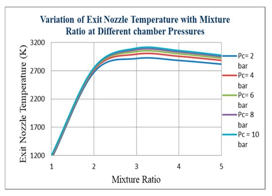
Figure 8.
Nozzle Exit Temperature vs. Mixture (O/F) ratio.
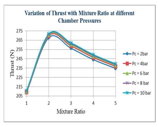
Figure 9.
Thrust vs. Mixture (O/F) Ratio.
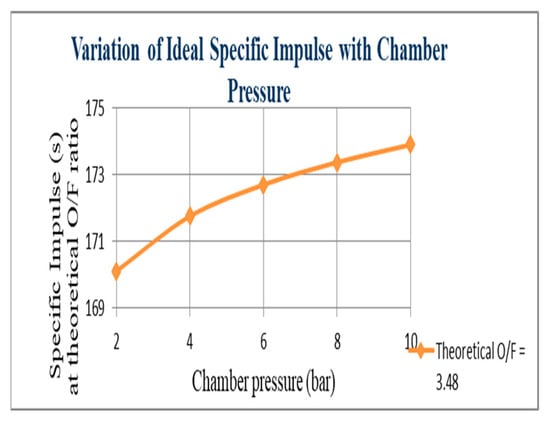
Figure 10.
Ideal Specific Impulse vs. Chamber Pressure.
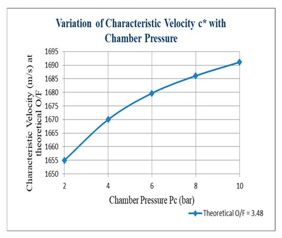
Figure 11.
Characteristic Velocity vs. Chamber Pressure.
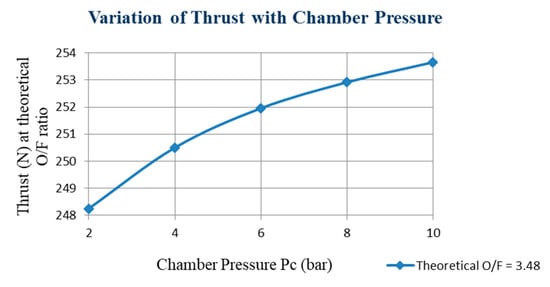
Figure 12.
Thrust vs. Chamber Pressure.
5. Conclusions
The current work presents a detailed study of the performance analysis of a liquid rocket engine. Liquid kerosene (fuel) reacting with gaseous oxygen (oxidizer) was investigated by considering the equilibrium flow condition during the expansion in the nozzle. The adiabatic flame temperature, characteristic velocity, specific impulse, and thrust over a range of mixture ratios from 1 to 5 with an interval of 1 along with the stoichiometric mixture ratio for a chamber pressure range of 2 to 10 bar with an interval of 2 were analyzed. The following are the outcomes of the analysis. The adiabatic flame temperature showed proportional growth with the mixture ratio between the ranges of 2 to 2.5 mixture ratios for all chamber pressures. The specific impulse increased proportionally with the increment of the mixture until the point at which the specific impulse value reached its peak, a point located between 2 and 2.5 mixture ratios for all chamber pressures. With a mixture ratio in the range of 2 to 2.25, characteristic velocity and thrust were highest for all considered chamber pressure values, and maximum at 2.25. At different chamber pressures, the ideal specific impulse, characteristic velocity, and thrust showed negligible increments with chamber pressures. Instead of considering large/small pressure values, the medium pressure value is better considered.
Author Contributions
Conceptualization, S.G.; methodology, S.G.; validation, P.B.; formal analysis, A.B.; investigation, K.S.; writing—original draft preparation, K.J.; writing—review and editing, S.G.; visualization, A.B.; supervision, P.B.; project administration, S.G. All authors have read and agreed to the published version of the manuscript.
Funding
This research received no external funding.
Institutional Review Board Statement
Not applicable.
Informed Consent Statement
Not applicable.
Data Availability Statement
No datasets were generated or analyzed during this study. This study presents a conceptual framework.
Conflicts of Interest
The authors declare no conflicts of interest.
References
- Sutton, G.P.; Biblarz, O. Rocket Propulsion Elements, 8th ed.; Wiley India Pvt Ltd.: Bengaluru, India, 2010. [Google Scholar]
- Hill, P.; Peterson, C. Mechanics and Thermodynamics of Propulsion, 2nd ed.; Pearson India: Bengaluru, India, 2010. [Google Scholar]
- Liu, G.; Hu, P. Review of liquid propellant rocket engine. Am. Inst. Aeronaut. Astronaut. 1998, 14, 2–6. [Google Scholar]
- Casiano, M.; Hulka, J.; Yang, V. Liquid-Propellant Rocket Engine Throttling, 1: A Comprehensive Review. In Proceedings of the 45th AIAA/ASME/SAE/ASEE Joint Propulsion Conference & Exhibit, Denver, CO, USA, 2–5 August 2009. [Google Scholar] [CrossRef]
- Singhal, R.; Toppo, C.; Roy, P.; Biswakarma, R.; Sahu, S.; Kalita, U. Development Advances in Liquid Rocket Engines Turbopump: A Review. Adv. Sci. Technol. 2023, 130, 155–162. [Google Scholar] [CrossRef]
- Kumar, G.; Krishnan, K.J.; Gokulakrishnan, S.; Lokeshwar, M.; Rogith, S. Design and Testing of a Liquid Rocket Engine; Springer: Berlin/Heidelberg, Germany, 2022. [Google Scholar] [CrossRef]
- Soller, S.; Behr, R.; Beyer, S.; Lehmann, M.; Preuss, A.; Salapete, R. Design and Testing of Liquid Propellant engine for Additive Manufacturing. Am. Inst. Aeronaut. Astronaut. 2017, 9, EUCASS 2017-306. [Google Scholar]
- Jeffrey, W.; Doug, R.; Brian, R.; Tucker, P.K. Designing Liquid Rocket Engine with reliable Injectors for Performance, Stability, and CoST. NASA Marshall Space Flight Cent. 2015, 6, 9–14. [Google Scholar]
- German Aerospace Center. Design and Fabrication of liquid rocket engine with 3D system. DLR-Dtsch.–und Raumfahrt 2004, 7, EUCASS 2004-306. [Google Scholar]
- Oefelein, J.C.; Yang, V. Comprehensive review of liquid propellant combustion instabilities in F-1 engine. J. Propuls. Power 2012, 9, 31–37. [Google Scholar] [CrossRef]
- Siva, V.; Sivakumar, R.; Prasaad, L. Combustion Instabilities and its Control Techniques for Liquid Propellant Rocket Engine. Int. J. Veh. Struct. Syst. 2023, 15, 1. [Google Scholar] [CrossRef]
- Casiano, M.J.; Hulka, R.; Yang, V. Design and Fabrication of dual manifold injector. J. Korean Soc. Propuls. Eng. 2010, 21, 41–47. [Google Scholar]
- Wei, Q.; Liang, G. Coupled Lagrangian impingement spray model for doublet impinging injectors under liquid rocket engine operating conditions. Chin. J. Aeronaut. 2017, 30, 1391–1406. [Google Scholar] [CrossRef]
- Mota, F.A.d.S.; Hinckel, J.N.; Rocco, E.M.; Schlingloff, H. Modeling and Analysis of a LOX/Ethanol Liquid Rocket Engine. J. Aerosp. Technol. Manag. 2018, 10, 9–14. [Google Scholar] [CrossRef]
- Santana, A., Jr.; Babosa, F.; Niwa, M.; Goes, L. Modeling and robust analysis of a liquid rocket engine. Am. Inst. Aeronaut. Astronaut. 2012, 6, 2000–3160. [Google Scholar]


Disclaimer/Publisher’s Note: The statements, opinions and data contained in all publications are solely those of the individual author(s) and contributor(s) and not of MDPI and/or the editor(s). MDPI and/or the editor(s) disclaim responsibility for any injury to people or property resulting from any ideas, methods, instructions or products referred to in the content. |
© 2025 by the authors. Licensee MDPI, Basel, Switzerland. This article is an open access article distributed under the terms and conditions of the Creative Commons Attribution (CC BY) license (https://creativecommons.org/licenses/by/4.0/).