1. Introduction
In industrial metal processing, radiant tubes are widely used due to their high efficiency and uniform heating characteristics [
1]. Currently, two types of radiant tubes are used: gas-fired and electrically heated radiant tubes [
2]. Among these, gas-fired radiant tubes exhibit higher thermal efficiency than electrically heated ones, which is why the current development trend favors gas-fired radiant tubes. Gas-fired radiant tubes heat workpieces through thermal radiation via the tube wall [
3]. However, this heating method introduces direct contact between the internal surface of the radiant tube and the combustion flame. This leads to the radiant tube wall being easily affected by localized high-temperature combustion, resulting in poor surface temperature uniformity [
4], increased stress on the tube, and deformation or cracking, which leads to tube damage [
5]. This not only shortens the lifespan of the radiant tube but also affects its heating capacity [
6]. Additionally, localized high temperatures increase NO
x and CO
2 emissions [
7,
8].
The common U-type and W-type gas-fired radiant tubes generally face the aforementioned issues [
9,
10]. Comparative studies of flow fields, temperature fields, and heat transfer characteristics of different types of radiant tubes have shown that the double P-type radiant tube is a better choice for a heat exchanger due to its self-preheating function [
11,
12]. Such a property is a significant advantage in temperature uniformity [
13]. This self-preheating function helps transfer the heat from high-temperature flue gases to the incoming air, significantly improving combustion efficiency and the uniformity of the tube wall temperature, and consequently, reducing thermal stress.
Moreover, if staged combustion technology is introduced in the double P-type radiant tube [
14], the flame temperature is effectively lowered by controlling the ratio of primary and secondary air effectively [
15,
16,
17] as the technology prevents NO
x emissions caused by air preheating and enhances temperature uniformity [
18]. Thus, the double P-type radiant tube can maintain high thermal efficiency while offering excellent temperature uniformity and low NO
x emissions.
2. Related Studies
The numerical simulation in this study is conducted based on prior research. References [
19,
20] provided critical guidance, particularly on the application of radiation and turbulence models, which are essential for accurately simulating heat transfer and flow behavior within radiant tubes. These models effectively describe the thermal radiation and turbulent diffusion processes of high-temperature combustion gases, providing a theoretical foundation for investigating flame characteristics and temperature distribution. Furthermore, the study results helped establish robust boundary conditions for this research, ensuring the accuracy and reproducibility of the simulation results.
The flame formation region in radiant tubes typically exhibits the highest temperature gradient on the tube walls [
21]. This not only induces localized thermal stress on the tube walls but also increases the likelihood of thermal strain and structural damage. This underscores the importance of analyzing this region to understand the thermal impact and stress distribution, whose results provide a basis for selecting suitable structural optimization methods. References [
22,
23] mentioned the common challenges faced by U-type radiant tubes, such as poor temperature uniformity, concentrated thermal stress, and high NO
x emissions. These issues limit the application of U-type radiant tubes, particularly in high-temperature operating environments, where their performance might degrade significantly.
These findings prompt the selection of the U-type radiant tube as a baseline for comparison in this study. Meanwhile, radiant tubes equipped with self-preheating functionality (and staged combustion functionality), such as the double P-type radiant tube, exhibit significant advantages in temperature uniformity, NOx emissions, thermal stress control, wall temperature difference reduction, and improved combustion efficiency. These provide a theoretical foundation for comparing the performance of U-type and double P-type radiant tubes under staged combustion configurations.
In particular, Wang et al. [
24] demonstrated that the installation of flame tubes inside the radiant tube significantly reduces the temperature difference along the inner wall. Their study also found that flame tubes tend to shift the high-temperature zone closer to the nozzle region, while heat-conducting strips have a relatively minor effect on temperature difference. However, they noted that the current flame tube bracket design may induce localized high-temperature zones, potentially leading to thermal stress concentration. These findings emphasize the need for optimized internal structural design to balance flame distribution and mechanical durability.
3. Methods
We utilized computational fluid dynamics (CFD) for numerical simulation and analysis to investigate the performance differences between the double P-type radiant tube with staged combustion functionality and the U-type radiant tube under three different inlet conditions. Simulations were conducted with varying sizes of staged combustion structures, and a comparative analysis was performed on the tube wall temperature distribution in the flame formation area and NOx emissions.
3.1. Boundary Conditions
For the simulation analysis, we set the air–fuel ratio to 10 as the inlet condition and designed three different inlet flow rates, specifically with air flows of 39, 52, and 65 m3/h, and corresponding natural gas volume flows of 3.9, 5.2, and 6.5 m3/h. The flue gas outlet was set with a pressure outlet of 0 pascal, and a gravity field of 9.81 m/s2 was applied in the Z direction. The simulated radiant tube was placed in a test furnace made of insulating bricks, with the furnace environment filled with air.
3.2. Flow Field Investigation in Industrial Furnace Gas-Fired Radiant Tubes
In this study, a three-dimensional model of the double P-type radiant tube and its surrounding flow field was established in SCDM 2023 R1. To save resources and reduce mesh generation time in the simulation, the radiant tube model was simplified to half of its symmetric portion.
Figure 1 presents the geometric models used in this simulation.
Figure 1a depicts the geometry of the U-type radiant tube, while
Figure 1b, illustrates the geometry of the double P-type radiant tube.
We set the air–fuel ratio to 10 and divided six different simulation cases based on flow rates of the double P-type and U-type radiant tubes: (a) a double P-type radiant tube with an airflow rate of 39 m3/h, (b) a double P-type radiant tube with an airflow rate of 52 m3/h, (c) a double P-type radiant tube with an airflow rate of 65 m3/h, (d) a U-type radiant tube with an airflow rate of 39 m3/h, (e) a U-type radiant tube with an airflow rate of 52 m3/h, and (f) a U-type radiant tube with an airflow rate of 65 m3/h.
We simulated three different flow rates to study the performance of radiant tubes and evaluate the differences in temperature uniformity, thermal strain, and NO
x emissions of the double P-type radiant tube equipped with self-preheating and staged combustion structures and the U-type radiant tube without these features ((a) to (f)). Additionally, as the self-preheating functionality in the double P-type radiant tube generates high temperatures, we designed four configurations of staged combustion nozzle structures as shown in
Figure 2, labeled as (g) to (j). These configurations differed in the dimensions of the staged combustion structures to control the mixing ratio of air and fuel at each stage. By adjusting the nozzle structure sizes, the mixing of primary and secondary air with fuel was varied, enabling an in-depth analysis of how the air–fuel ratio impacts combustion characteristics and overall performance. This approach allowed us to assess the influence of these functionalities on the performance of radiant tubes.
Previous studies have shown that the flame formation area of radiant tubes exhibits higher wall temperatures. Therefore, we analyzed the temperature distribution and thermal strain in the central straight section of the double P-type radiant tube and the left straight section of the U-type radiant tube.
4. Result
The cross-sectional temperature distribution (
Figure 3) showed that the flame reaction zone is located in the central straight section of the radiant tube, while higher temperatures are concentrated near the lower ends on both sides. The temperature distribution of the flow field indicates that the surface temperature gradient on the central tube wall is smaller compared to the side sections. As the flow rate increases, the high-temperature region of the flame shifts closer to the bottom of the tube.
Figure 4 shows that the temperature difference on the inner wall of the radiant tube is higher, while the temperature difference on the outer wall is relatively lower. Compared to the radiant tubes with flow rates of 3.9 and 5.2 m
3/h, the simulation results at a flow rate of 6.5 m
3/h indicate a higher surface temperature. Additionally, as the flame moves closer to the bottom, the temperature of the bottom wall also increases significantly. Furthermore, the surface temperature differences under these conditions are notably greater than those observed in the previous two tests.
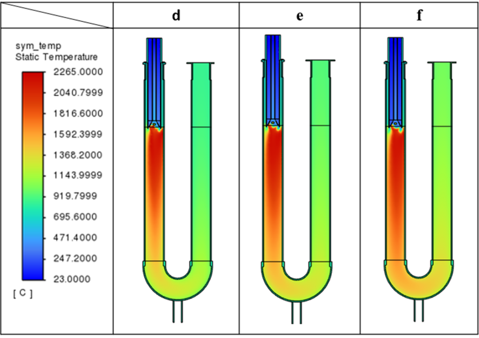
The temperature distribution of the cross-sectional flow field of the U-shaped radiant tube indicates that the flame formation is concentrated on the left side of the tube (
Figure 5). Compared with the double P-shaped radiant tube under the same flow rate, the U-shaped radiant tube exhibits a higher flame temperature. This result indicates that the flame temperature distribution in the U-shaped radiant tube is more concentrated than the P-type radiant tube under the same conditions, which increases local temperature and NO
x emissions.
The U-shaped radiant tube has a higher wall temperature and a greater wall temperature difference, particularly in the flame formation area, than the double P-shaped radiant tube under the same flow rate, where the difference is more pronounced (
Figure 6).
For the average wall temperature in the flame formation region, the double P-type radiation tube with staged combustion and self-preheating functions is superior to the U-type radiation tube and the double P-shaped radiant tube under the same flow rate. Additionally, the NO
x emissions of the double P-type radiation tube are significantly lower than those of the U-type radiation tube (
Table 1 and
Table 2).
Thermal strain analysis was conducted on double P-type and U-type radiation tubes with three different inlet flow rates without adjusting the nozzle holes. The thermal strain is mainly concentrated in the high-temperature areas of the radiation tube walls, and the thermal strain of the U-type radiation tube is significantly greater than that of the double P-type, with a broader distribution range (
Figure 7 and
Figure 8). As the inlet flow rate increases, the thermal strain of the radiation tubes shows an increase, indicating that the larger airflow rates of the radiation tubes subjected to higher thermal loads cause severe strain.
We explored the four different nozzle characteristics of the double P-type radiant tube. While keeping other structural elements unchanged and setting the same inlet conditions, the nozzle diameters were adjusted. With the reduction in the nozzle diameter, the flame formation gradually shifts toward the bottom bend of the tube, and the flame becomes elongated (
Figure 9). This change simultaneously affects the size and temperature distribution of the flame, indicating that the nozzle diameter has a significant impact on the flame shape and heat transfer characteristics.
The average temperature of the bottom and side walls increases as the flow field moves downstream, with the temperature difference also gradually increasing (
Figure 10). In contrast, the average temperature of the middle remains lower, indicating the thermal distribution characteristics under this condition.
As shown in
Table 3, both the outer and inner wall temperature differences increase, while NO
x emissions decrease after changing the nozzle size at the staged combustion area.
5. Conclusions
The results indicate that, under identical operating conditions, the U-shaped radiant tube develops a higher flame temperature than the double P-type tube. As a consequence, the U-shaped tube exhibits markedly higher wall temperatures and much larger wall-temperature gradients than its double P-type counterpart, leading to greater thermal strain that is particularly concentrated in the flame-formation region. The wall-temperature gradient of the U-shaped radiant tube is therefore significantly larger than that of the double P-type tube.
In contrast, the double P-type radiant tube, benefiting from its internal structural advantages, demonstrates a more uniform thermal field and a notable reduction in thermal load. Regarding NOx emissions, the optimal configuration of staged combustion combined with small-diameter nozzles successfully reduces NOx concentration to one-twentieth of its original level, indicating the effective suppression of high-temperature zones and the mitigation of NOx formation.
Furthermore, the simulations reveal that flame position and shape shift significantly with nozzle diameter. As the nozzle diameter decreases, the flame tends to move toward the bottom bend of the tube, leading to increased average temperatures and temperature differences on the bottom and side walls. Wall-temperature gradients and thermal strain also rise with higher inlet flow rates, indicating that radiant tubes operating under high-flow conditions are subjected to more severe thermal loads. Thermal stress analysis further shows that the U-shaped radiant tube exhibits significantly higher stress values and a wider distribution range compared with the double P-type tube, indicating that the U-shaped structure is more susceptible to stress concentration and material fatigue under high-temperature and high-heat-flux conditions.
Conversely, the reduced thermal stress observed in the double P-type tube helps improve structural reliability, prolong service life, and lower the risk of material degradation or failure during long-term operation, especially in harsh thermal environments.
These findings extend the flame-tube optimization work by Wang et al. (2023) [
24] and provide actionable guidelines for designing next-generation, low-emission, radiant-tube burners.
Author Contributions
Conceptualization, W.-L.C. and C.-H.T.; methodology, T.-J.C. and C.-H.T.; software, C.-C.L.; validation, C.-C.L. and T.-J.C.; formal analysis, T.-J.C.; investigation, C.-C.L.; resources, W.-L.C.; data curation, C.-C.L.; writing—original draft preparation, C.-C.L.; writing—review and editing, T.-J.C.; visualization. C.-C.L.; supervision, T.-J.C.; project administration, W.-L.C.; funding acquisition, W.-L.C. All authors have read and agreed to the published version of the manuscript.
Funding
This research received no external funding.
Institutional Review Board Statement
Not applicable.
Informed Consent Statement
Not applicable.
Data Availability Statement
All relevant data are within the paper.
Conflicts of Interest
The authors declare that they have no conflicts of interest.
References
- Xu, Q.; Feng, J. Simulation and structural optimization of flat double-P type radiant tubes based on the orthogonal method. Chin. J. Eng. 2017, 39, 581–592. [Google Scholar]
- Charles, E.B., Jr. Radiant Tube Burners. In Industrial Combustion Testing, 1st ed.; Michael, F., Joachim, G.W., Wlodzimierz, B., Weihong, Y., Darius, S., Jun, S., Susumu, M., Ambrogio, M., Eds.; CRC Press: Boca Raton, FL, USA, 2010. [Google Scholar]
- Lenz, W.; Brykarczyk, D.; Pfeifer, H.; Neumann, A.; Bambach, M. Theoretical limits of the increase of radiative heat transfer by increased surface areas of radiant tubes. Appl. Therm. Eng. 2021, 184. [Google Scholar] [CrossRef]
- Fan, H.; Feng, J.; Xie, K.; Bai, W.; Zhao, Y.; Li, W.; Gao, J.; Liu, C.; Yan, D.; Zhao, H. Experimental study of operating parameters on the performance of a novel U-type radiant tube with dual flue gas self-circulation structures. Appl. Therm. Eng. 2022, 207. [Google Scholar] [CrossRef]
- Irfan, M.A.; Chapman, W. Thermal stresses in radiant tubes due to axial, circumferential and radial temperature distributions. Appl. Therm. Eng. 2009, 29, 1913–1920. [Google Scholar] [CrossRef]
- Irfan, M.; Chapman, W. Thermal stresses in radiant tubes: A comparison between recuperative and regenerative systems. Appl. Therm. Eng. 2010, 30, 196–200. [Google Scholar] [CrossRef]
- Feng, J.; Jiang, M.; Cao, Y.; Chen, Y.; Wu, Q.; Xiang, S. Numerical investigation on the low NOx emission of W-shaped radiant tubes. Chin. J. Eng. 2014, 36, 1094–1100. [Google Scholar]
- Gao, Q.; Pang, Y.; Sun, Q.; Liu, D.; Zhang, Z. Numerical analysis of the heat transfer of radiant tubes and the slab heating characteristics in an industrial heat treatment furnace with pulse combustion. Int. J. Therm. Sci. 2021, 161, 106757. [Google Scholar] [CrossRef]
- Xu, Q.; Feng, J.; Ding, C.; Chang, C.; Xiong, Y.; Zang, Y.; Du, Z.; Jia, L. Influence of the operating parameters and nozzle characteristics on flat double-P radiant tube performance. Appl. Therm. Eng. 2019, 155, 175–184. [Google Scholar] [CrossRef]
- Wu, T.; Tan, F.; Xu, J.; Li, D.; Gao, L.; Li, F. Numerical simulation of natural gas-ammonia combustion characteristics in a U-shaped radiant tube. Fuel 2025, 381, 133343. [Google Scholar] [CrossRef]
- Ahanj, M.D.; Rahimi, M.; Alsairafi, A.A. CFD modeling of a radiant tube heater. Int. Commun. Heat Mass Transf. 2012, 39, 432–438. [Google Scholar] [CrossRef]
- Gupta, A.K.; Bolz, S.; Hasegawa, T. Effect of Air Preheat Temperature and Oxygen Concentration on Flame Structure and Emission. Energy Resour. Technol. 1999, 121, 209–216. [Google Scholar] [CrossRef]
- Xu, Q.; Feng, J.; Zhou, W.; Chen, Y. Location characteristics of the nozzle structure in the double P-type radiant tube. Chin. J. Eng. 2017, 39, 756–761. [Google Scholar]
- Wang, Y.; Zhou, Y.; Bai, N.; Han, J. Experimental investigation of the characteristics of NOx emissions with multiple deep air-staged combustion of lean coal. Fuel 2020, 280, 118416. [Google Scholar] [CrossRef]
- Scribano, G.; Solero, G.; Coghe, A. Pollutant emissions reduction and performance optimization of an industrial radiant tube burner. Exp. Therm. Fluid Sci. 2006, 30, 605–612. [Google Scholar] [CrossRef]
- Cheng, S.; Yong, H.; Wu, C. Decreasing of Nox Emission in Fired-natural Gas Radiant-tube with Regenerative Combustor. J. Chongqing Univ. 2008, 31, 271–275. [Google Scholar]
- Zhou, W.; Su, F.; Zhang, L.; Li, T. Enhanced NOx reduction performance in the I-type radiant tube by combining a novel triple air-staging with flue gas recirculation. Case Stud. Therm. Eng. 2022, 39, 102380. [Google Scholar] [CrossRef]
- Xu, Q.; Feng, J.; Zhou, W. Numerical simulation and research on the effect of the classification of gas composition on the heat process of gas radiation tubes. Chin. J. Eng. 2017, 39, 96–106. [Google Scholar]
- Tsioumanis, N.; Brammer, J.G.; Hubert, J. Flow processes in a radiant tube burner: Combusting flow. Energy Convers. Manag. 2011, 52, 2667–2675. [Google Scholar] [CrossRef]
- Uygur, A.B.; Tarhan, T.; Selçuk, N. Transient simulation of reacting radiating flows. Int. J. Therm. Sci. 2006, 45, 969–976. [Google Scholar] [CrossRef]
- Feng, J.; Jiang, M.; Zhou, W.; Wu, Q.; Xiang, S. Flow heat transfer and NOx emission characteristic of W-shaped radiant tubes with flue gas circulation. Chin. J. Eng. 2014, 36, 1552–1559. [Google Scholar]
- Fan, H.; Feng, J.; Bai, W.; Wang, H.; Akkurt, N.; Li, W.; Gao, J.; AliAkbaria, O.; Xu, Q. A study on the combustion performance and NOx emissions characteristics of a novel U-type radiant tube based on MILD combustion theory. Fuel 2023, 346, 128321. [Google Scholar] [CrossRef]
- Tian, Y.; Liu, X.; Zhou, X.; Lin, S.; Li, Z.; Zhang, D. Experimental study on W-shaped regenerative radiant tube with novel structure burner for performance optimization. Exp. Heat Transf. 2017, 31, 131–147. [Google Scholar] [CrossRef]
- Wang, C.-C.; Chen, T.-J.; Cheng, W.-L. Computer Numerical Simulations of Gas-Fired Radiant Tubes. In Proceedings of the 2023 IEEE 5th Eurasia Conference on IoT, Communication and Engineering (ECICE), Yunlin, Taiwan, 27–29 October 2023. [Google Scholar]
Figure 1.
Geometric models of the radiant tubes: (a) U-type radiant tube; (b) double P-type radiant tube.
Figure 1.
Geometric models of the radiant tubes: (a) U-type radiant tube; (b) double P-type radiant tube.
Figure 2.
Design of secondary air outlet nozzle hole diameters for various sizes: (g) 16 mm, (h) 13 mm, (i) 10.5 mm, (j) 8 mm.
Figure 2.
Design of secondary air outlet nozzle hole diameters for various sizes: (g) 16 mm, (h) 13 mm, (i) 10.5 mm, (j) 8 mm.
Figure 3.
Cross-sectional flow field temperature distribution for different airflow rates: (a) airflow rate of 39 m3/h, (b) airflow rate of 52 m3/h, (c) airflow rate of 65 m3/h.
Figure 3.
Cross-sectional flow field temperature distribution for different airflow rates: (a) airflow rate of 39 m3/h, (b) airflow rate of 52 m3/h, (c) airflow rate of 65 m3/h.
Figure 4.
Internal and external wall temperature distribution of Case (a), Case (b), and Case (c).
Figure 4.
Internal and external wall temperature distribution of Case (a), Case (b), and Case (c).
Figure 5.
Cross-sectional flow field temperature distribution for different airflow rates: (d) airflow rate of 39 m3/h, (e) airflow rate of 52 m3/h, (f) airflow rate of 65 m3/h.
Figure 5.
Cross-sectional flow field temperature distribution for different airflow rates: (d) airflow rate of 39 m3/h, (e) airflow rate of 52 m3/h, (f) airflow rate of 65 m3/h.
Figure 6.
Internal and external wall temperature distribution of Case (d), Case (e), and Case (f).
Figure 6.
Internal and external wall temperature distribution of Case (d), Case (e), and Case (f).
Figure 7.
The thermal strain of the wall of Case (a), Case (b), and Case (c).
Figure 7.
The thermal strain of the wall of Case (a), Case (b), and Case (c).
Figure 8.
The thermal strain of the wall of Case (d), Case (e), and Case (f).
Figure 8.
The thermal strain of the wall of Case (d), Case (e), and Case (f).
Figure 9.
Cross-sectional flow field temperature cases for different secondary air outlet nozzle hole diameters: (g) 16 mm, (h) 13 mm, (i) 10.5 mm, (j) 8 mm.
Figure 9.
Cross-sectional flow field temperature cases for different secondary air outlet nozzle hole diameters: (g) 16 mm, (h) 13 mm, (i) 10.5 mm, (j) 8 mm.
Figure 10.
Internal and external wall temperature distribution of Case (g), Case (h), Case (i), and Case (j).
Figure 10.
Internal and external wall temperature distribution of Case (g), Case (h), Case (i), and Case (j).
Table 1.
Wall temperature in the flame formation region at different flow rates.
Table 1.
Wall temperature in the flame formation region at different flow rates.
| Case | a | b | c |
|---|
| Temperature difference between the maximum and minimum on the inner wall (°C) | 22.24 | 18.79 | 34.84 |
| Temperature difference between the maximum and minimum on the outer wall (°C) | 20.77 | 16.47 | 33.50 |
| Case | d | e | f |
| Temperature difference between the maximum and minimum on the inner wall (°C) | 62.40 | 69.46 | 76.96 |
| Temperature difference between the maximum and minimum on the outer wall (°C) | 50.34 | 55.67 | 62.73 |
Table 2.
NOx emissions at different flow rates.
Table 2.
NOx emissions at different flow rates.
| Case | a | b | c |
|---|
| NOx Concentration in Exhaust Gas (ppm) | 19.89 | 10.30 | 15.96 |
| Case | d | e | f |
| NOx Concentration in Exhaust Gas (ppm) | 490.59 | 407.09 | 293.28 |
Table 3.
Wall temperature in the flame formation region with different nozzle sizes.
Table 3.
Wall temperature in the flame formation region with different nozzle sizes.
| Case | g | h | i | j |
|---|
| Temperature difference between the maximum and minimum on the inner wall (°C) | 25.52 | 28.86 | 29.71 | 37.38 |
| Temperature difference between the maximum and minimum on the outer wall (°C) | 22.36 | 24.74 | 25.42 | 31.98 |
| NOx Concentration in Exhaust Gas (ppm) | 57.32 | 28.70 | 17.34 | 6.09 |
| Disclaimer/Publisher’s Note: The statements, opinions and data contained in all publications are solely those of the individual author(s) and contributor(s) and not of MDPI and/or the editor(s). MDPI and/or the editor(s) disclaim responsibility for any injury to people or property resulting from any ideas, methods, instructions or products referred to in the content. |
© 2025 by the authors. Licensee MDPI, Basel, Switzerland. This article is an open access article distributed under the terms and conditions of the Creative Commons Attribution (CC BY) license (https://creativecommons.org/licenses/by/4.0/).


