Abstract
We improved signal reception by minimizing interference in dynamic communication environments with a minimum-variance distortionless response (MVDR) algorithm. The conditions of the MVDR algorithm were simulated using MATLAB and GNU Radio to enhance its capabilities in noise and interference suppression. Through a MATLAB simulation, the adaptive beamforming performance of MVDR was examined and compared with that of conventional beamforming techniques to identify the advantages of beam steering for obtaining the desired signals. MVDR was effective in interference reduction and the improvement of signal clarity, with superiority over conventional approaches in cases with complex interference patterns. Based on the results of the MATLAB simulations, GNU Radio was used in a complete software-defined radio (SDR) environment that enabled the replication of real-world conditions to study MVDR. We simulated real-world applications by integrating GNU Radio to ensure the robustness and adaptability of the algorithm in live signal processing. The results from these two simulations prove the potential of MVDR as a strong dynamic interference suppressor that enables superior signal reception. The results enable the implementation of the MVDR algorithm in communication systems.
1. Introduction
Conventional beamforming methods, such as distributed antenna system (DAS) beamforming, are widely used in antenna array systems. However, since they are unable to effectively cancel noise and suppress interference in a complicated signal environment, conventional methods do not improve signal transmission. Due to such limitations, high-performance communication systems, which require high levels of signal directionality and noise reduction [1], cannot be used with conventional beamforming, and this limits its usage in high-performance communication systems. This limitation also prevents conventional beamforming from meeting the needs of next-generation systems in a complex system. As a result, robust interference rejection with higher precision is required. Advanced adaptive techniques can be used to enhance efficiency and accuracy by minimizing interference and amplifying target signals.
The minimum-variance distortionless response (MVDR) algorithm is efficient and productive in changing interference patterns as it suppresses interference while maintaining the integrity of the desired signal. This makes MVDR a compelling choice for advanced signal processing in complex, high-demand environments.
Table 1 shows a comparison between beamforming with and without MVDR. MVDR shows significant improvements in signal power retention, the enhancement of the desired signal, and interference reduction compared to many classical techniques [2,3]. MVDR optimally adjusts the beam pattern and minimizes the interference and noise contributions in other directions with outstanding performance in the presence of severe interference. MVDR shows great performance in speech enhancement and noise reduction with high signal fidelity, effectively improving the signal-to-noise ratio (SNR) compared to that of conventional beamforming or multiple-signal classification (MUSIC) [2,3,4]. MVDR also performs better in arrival estimation (DOA) and presents a higher-resolution signal source than DASs [3].

Table 1.
Comparison of MVDR and conventional beamforming.
Despite the theoretical advantages of the MVDR algorithm [2,3,4] and modification methods [5], the use of MVDR was not investigated for antenna systems in this study. Due to its computational complexity and the challenge of accurately estimating and inverting the covariance matrix [2], its operations require significant processing power, which hinders real-time implementation, especially for large arrays or rapidly changing environments. Consequently, MVDR has often been overlooked despite having a simple and computationally feasible method and superior interference rejection and resolution capabilities.
In this study, we addressed such challenges by exploring MVDR in terms of interference reduction and desired signal enhancement. We used two simulation platforms, MATLAB R2023a and GNU Radio. We simulated MVDR implementation using MATLAB to comprehend MVDR’s applications in adaptive beamforming.
This article is organized as follows. The second section introduces the MVDR algorithm and presents its architecture, along with its operating principles. Section 3 compares the proposed MVDR-based system with a conventional beamforming approach in the context of an antenna array, highlighting its improved performance and signal integrity. Section 4 presents the simulation results for MVDR’s integration into a GNU Radio system to verify the effectiveness of noise and interference reduction. The benefits of MVDR in a complex signal environment are explained, too. The algorithm’s advantages and the capabilities of the MVDR algorithm are explained in the last section.
2. Methodology
The equations and theoretical concepts underlying the MVDR and conventional beamforming algorithms are compared. MVDR beamforming maximizes the reception of the desired signal while minimizing the interference and noise. Uniform weights are used in the comparison to steer the array in the desired direction without interference suppression. The simulation was conducted with an array of sensors, M, a desired signal arriving from angle θs, and an interference source at angle θi.
2.1. Steering Vector Calculation
The steering vector represents the phase shifts across array elements for a signal arriving at a particular angle. For an array with M elements and an inter-element spacing, d, the steering vector for an angle, θ, is given as
where is the wave number with λ as the wavelength, d is the inter-element spacing, and θ is the arrival angle of the signal.
The steering vector aligns the phases of the incoming signal across the array of elements and enables constructive interference in the desired direction.
2.2. Conventional Beamforming
Conventional beamforming uses uniform weights to direct the array’s main beam toward the desired signal direction without suppressing interference. The conventional beamforming weight vector wCBF is equally weighted (2).
The power of the beam pattern in the direction θ for conventional beamforming is then calculated as
While it is simple to implement, conventional beamforming lacks the adaptive interference reduction capabilities of MVDR and results in high sidelobe levels in the interference directions. In conventional beamforming, estimating the received signal’s interference and noise is crucial. Given a received signal matrix, the covariance matrix is constructed as
where N is the number of snapshots (samples in time), X is an M × N matrix representing the signals received by each array element over time, and XH is the Hermitian transpose of X.
This matrix describes the spatial correlation of the signals at the various array elements and allows the MVDR beamformer to distinguish the desired signal from the interference.
2.3. MVDR Weight Vector
The MVDR beamforming weights are calculated to minimize the output power while ensuring a distortionless response in the desired signal direction. The MVDR weight vector wMVDR is calculated as
where R−1 is the inverse of the covariance matrix, a(θs) is the steering vector for the desired signal direction θs, and a(θs)HR−1a(θs) is a normalization factor to ensure the beamformer achieves a unit gain in the desired signal direction.
Equation (5) is used to estimate the maximum reduction in the power received from the interference directions while maintaining the desired signal with no distortion.
2.4. Beam Pattern and Output Power
The beam pattern describes how the beamformer responds to signals arriving from different angles. The power of the beam pattern in a direction is computed as
Using (6), the response of the beamformer to incoming signals at angle θ is estimated by projecting the weight vector w onto the steering vector a(θ). The beam pattern was plotted before and after applying MVDR beamforming to illustrate how this algorithm suppresses the interference of the desired signal.
2.5. Signal-to-Interference-Plus-Noise Ratio (SINR)
Equation (7) provides a quantitative measure of the MVDR algorithm’s performance by comparing the desired signal power against the combined interference and noise power. Equation (7) also defines the MVDR and conventional beamforming processes, showing the difference in the interference rejection and directional gain. In the simulation, the metrics were calculated to show how MVDR effectively achieved a strong signal enhancement compared with conventional methods.
3. MATLAB Simulation
3.1. Initial Setup
In the simulation, the parameters were set using the equations presented in Section 2. The key parameters were determined in the initial setup as follows:
- The number of array elements (M): We set the number of array elements to M = 8. This is a typical configuration for simulating narrowband array beamforming to balance computational complexity and the spatial resolution.
- Inter-element spacing (d): The spacing between two adjacent elements was set to d = 0.5λ, where λ represents the wavelength of the incoming signal. We chose this value to avoid grating lobes while allowing for sufficient beamforming flexibility.
- Frequency and wavelength: The signal frequency was set to f = 1, corresponding to a wavelength of λ = 1. We also set the speed of wave propagation c to 1 for simplicity.
- Sampling frequency and snapshots: The sampling frequency was set to fs = 1000 Hz across N = 1000 snapshots.
- Desired and interference signal angles: The desired signal arrived from an angle of θs = 30°, while the interference signal arrived from θi = −20°.
- The SNR for the desired signal was set to 20 dB. The SNR represents the relative power of the signal compared to noise. The SNR was used to assess how effectively the beamformer enhanced the desired signal in a noisy environment.
- The SINR was set to 30 dB for assessing the beamformer’s interference reduction ability in the presence of both interference and noise.
We constructed the covariance matrix and applied the MVDR beamforming algorithm to calculate the optimal weights for the array. The results obtained using MVDR showed how it performed compared with conventional beamforming. Improvements in the beam patterns, SINR, and output signal characteristics after MVDR beamforming were observed in the simulation.
3.2. Simulation Results of MATLAB
We compared the two beam patterns shown in Figure 1. MVDR beamforming focused on a desired signal direction while suppressing interference. Two curves present the results for the conventional beamforming pattern with uniform weights and the MVDR beamforming pattern. The conventional beamforming method showed a wide main lobe, caused by receiving signals with a comprehensive range of angles. However, it did not reduce the interference. In contrast, the MVDR pattern had a narrow main lobe and showed a focus on the direction of the desired signal at θ = 30°, while creating a deep null at the interference angle θi = −20°. This capability for mitigating interference showed how the adaptive MVDR algorithm dynamically adjusted the weights to suppress undesired signals and increased the directional sensitivity and interference rejection. Figure 1 also shows the difference between the normalized power in the beam patterns with and without the use of the MVDR algorithm. The spectrum showed that the normalized power gained in MVDR beamforming was higher than that in conventional beamforming. The power usage in the system with the MVDR algorithm was enhanced, increasing the strength of the signal received while the signal reception stayed within the desired range when using MVDR.
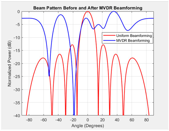
Figure 1.
Beam pattern with and without MVDR beamforming.
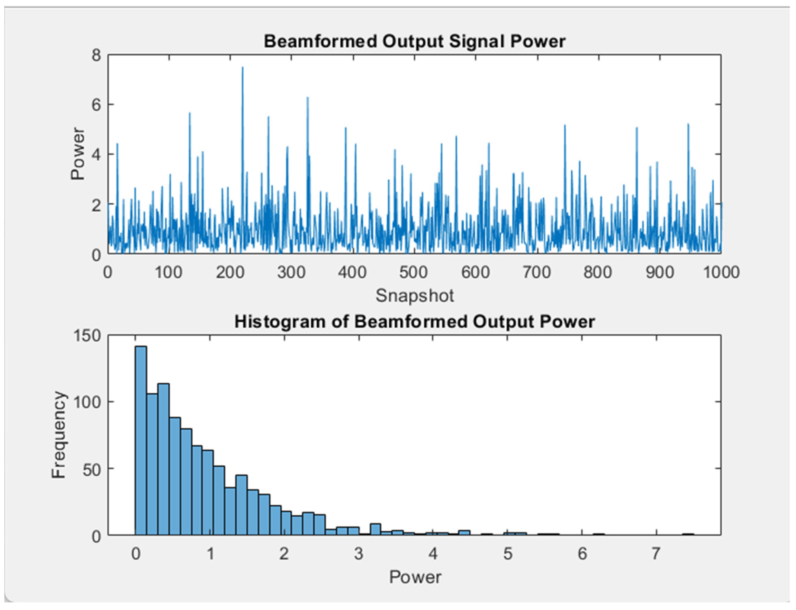
In Figure 2, the upper graph shows the instantaneous power of the beamformed output signal over the snapshots. Although the power levels changed due to the noise and interference, the MVDR algorithm smoothed the fluctuations to such an extent that it enhanced the dominance of the desired signal. The lower graph shows a histogram of the output power and the distribution of the power levels over the snapshots. The histogram is skewed to the lower end of the power levels, corresponding to high power and snapshots with a strong signal. The distribution proves that MVDR beamforming limited interference successfully as the output power had a lower mean level than the one generated through uniform beamforming.

Figure 2.
Output signal and histogram of output power.
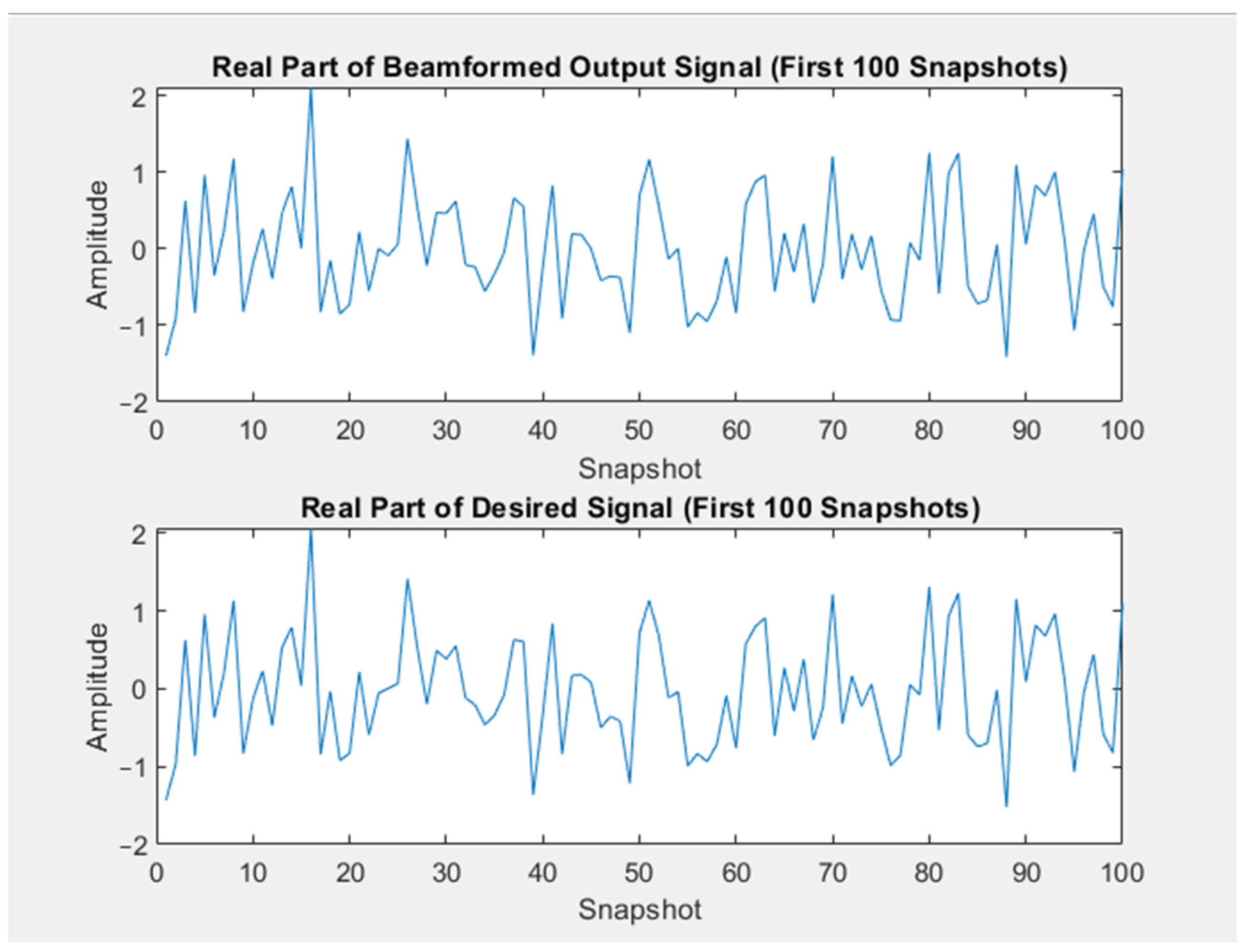
The real values of the beamformed output signal were compared with those of the desired signal over the first 100 snapshots (Figure 3). The similarity in the patterns between the two plots shows that MVDR beamforming successfully isolated and extracted the desired signal components from the received data. The MVDR algorithm reduced the interference to a negligible level and had a negligible effect on the desired output signal. Despite a fluctuation due to the residual noise, MVDR beamforming captured the structure of the desired signal effectively, enhanced signals, and suppressed interference.
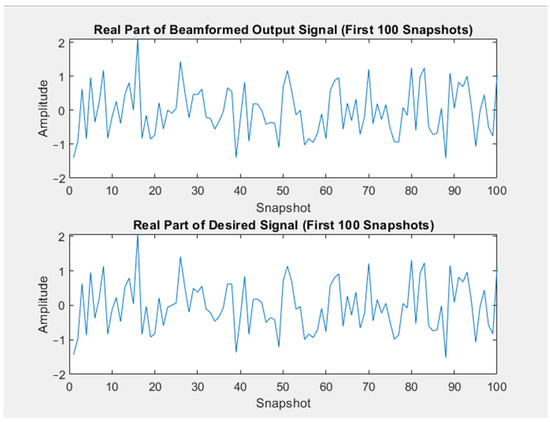
Figure 3.
Original desired signal and MVDR-processed desired signal.
The results illustrated that MVDR beamforming resulted in a better-quality desired signal and a greater ability to reduce interference than conventional beamforming. The tighter main lobe and deeper nulls in the beam pattern and the stability and alignment of the beamformed output signal were comparable with those of the desired signal.
4. GNU Radio Simulation
4.1. Antenna System in GNU Radio
The established model optimized the performance of a smart antenna. The model simulated in GNU Radio consisted of the input device (signal source and noise source), the MVDR algorithm, and the output display devices (the QT GUI sink and the time sink). Figure 4 demonstrates the antenna model which was constructed and used in this research.
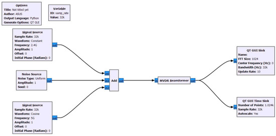
Figure 4.
Combination of algorithms.
The embedded algorithm block was responsible for creating the MVDR algorithm, which processed signals from output devices such as the QT time sink block. The antenna model maintained the simulated signal and interference to test whether the algorithm enhanced signal reception and reduced interference.
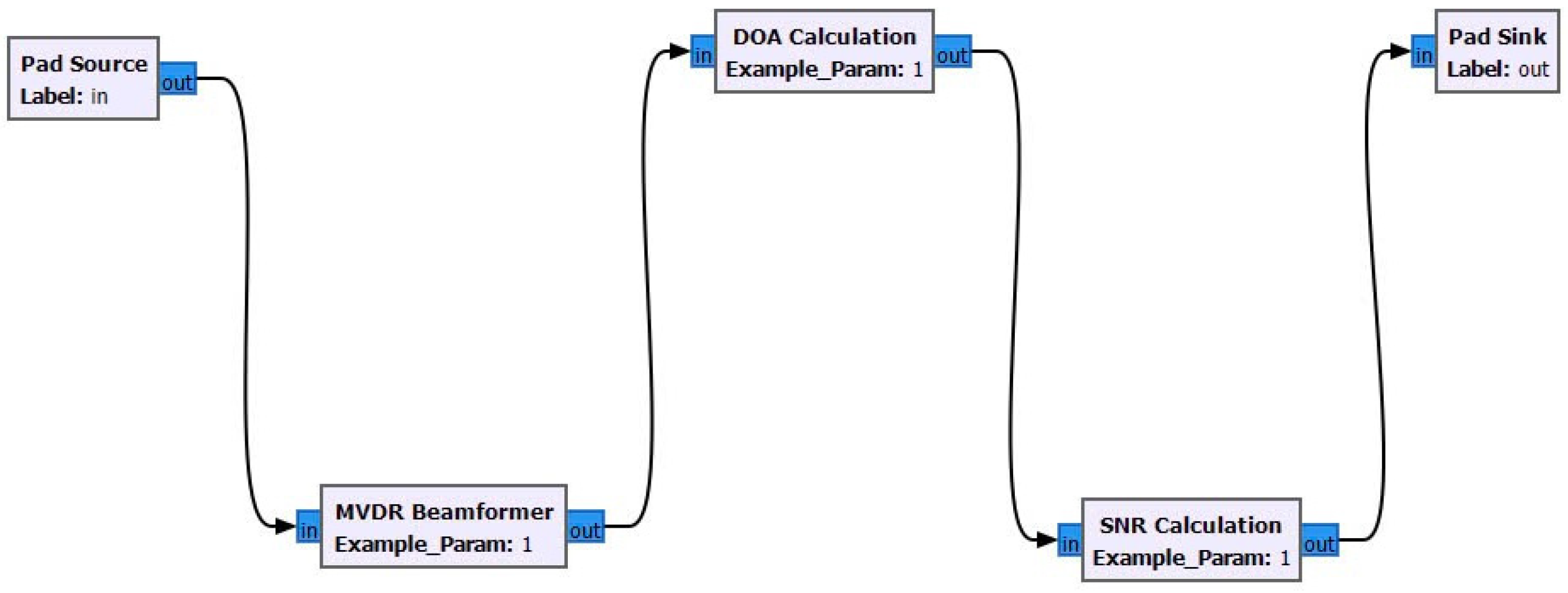
The MVDR beamformer block was a combination of the MVDR beamformer, DOA calculation, and SNR calculation (Figure 5), with each block being responsible for data processing. The calculated data from the previous block were sent to the next block to display the results on the output devices. Each input device was designed to generate different waveforms at various frequencies, while the output devices had different update rates. The sample rate of all input/output devices was set to 32,000 to ensure that the flow graph data were synchronized with consistent signal processing while avoiding buffer overflows and underflows.
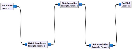
Figure 5.
Embedded algorithm block.
4.2. Simulation Results of GNU Radio Application
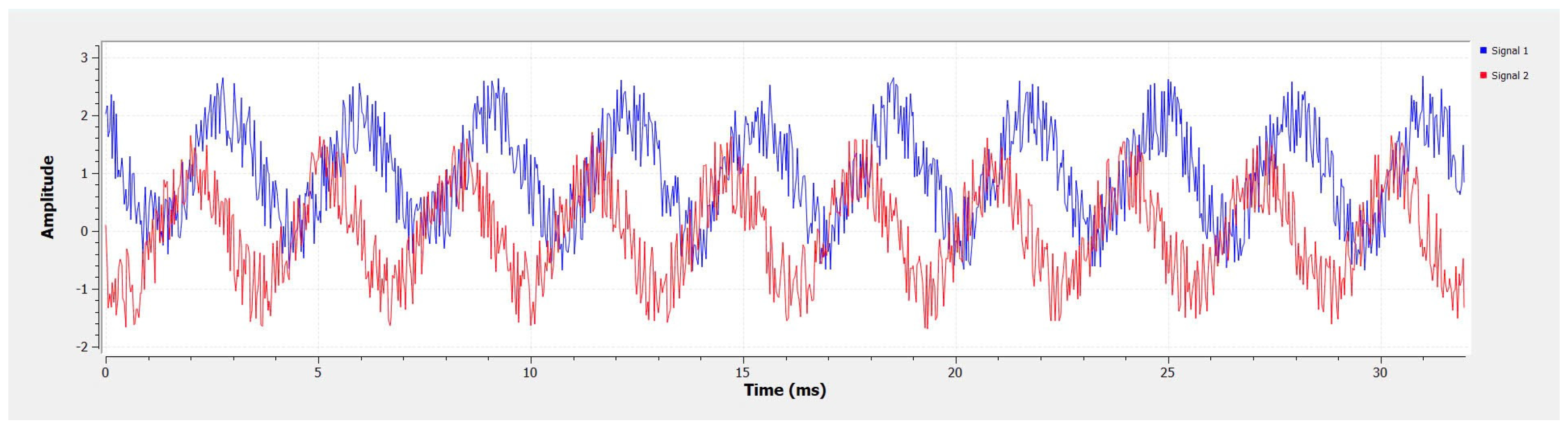
Figure 6 shows the combination of signals and noises, which exhibited a regular oscillatory pattern with amplitude fluctuations. The system experienced interference from the noise source. The shape of the two signals showed a similar pattern, indicating that the two channels received different signals with two different frequency parameters. The amplitudes of the signal were maintained within a range of approximately −2 to 3, which demonstrated that the antenna system performed according to the system’s requirements.
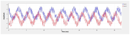
Figure 6.
Results in time domain.
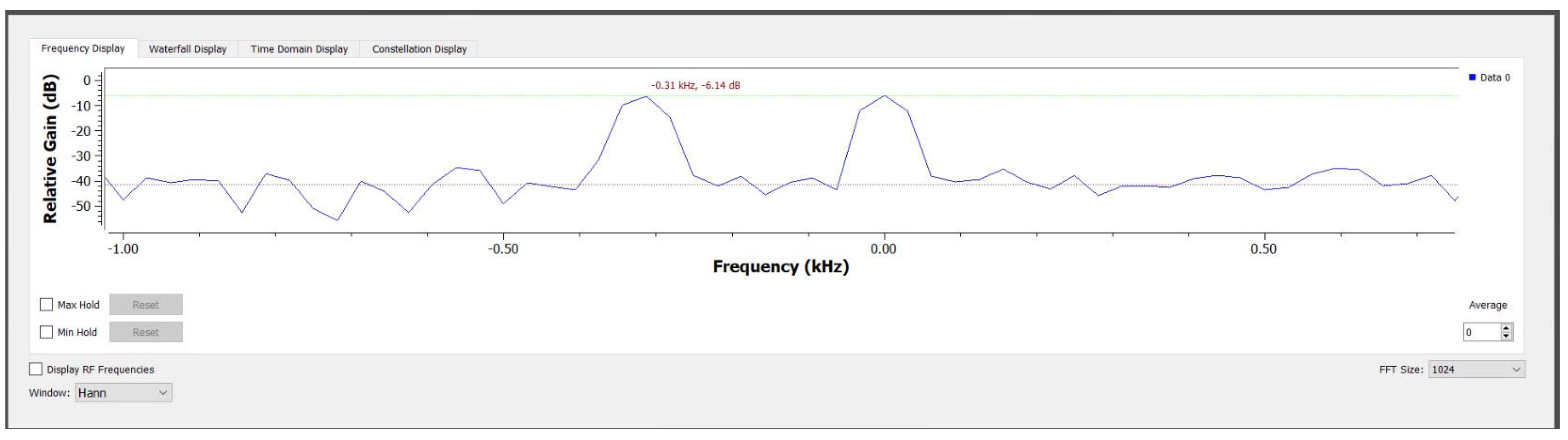
Figure 7 depicts the frequency spectrum of a signal, with the signal processing parameters of a Hann window setting and FFT size of 1024. The frequency data is also represented in the graph with the green line signifies the peak value of the signal system while the black dot demonstrates the average relative gain of the collected data. The figure shows the dominant frequency components with reduced spectral leakage. The antenna model’s average relative gain fluctuated from around −38 to −50 dB with a peak of −6.14 dB at −0.31 and 0.0 kHz. The results showed that the collected data had stability in the antenna model across this frequency range while reaching a relative peak at two different frequencies.
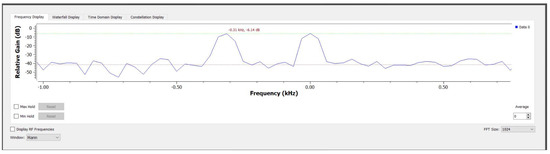
Figure 7.
Frequency of antenna system.
For better interference identification, the data were visualized using blue dots, as shown in Figure 8. The relationship between the two variables, in-phase (on the X-axis) and quadrature (on the Y-axis), is presented in the figure. Blue data points were densely clustered in an elliptical shape, indicating how the antenna system perceived the signal and noise source. The data points were dispersed horizontally and vertically, showing that the antenna model was affected by noise and interference. Despite the interference from the noise sources, the system captured signals by adjusting or adding additional noise reduction algorithms.
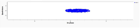
Figure 8.
Collected data in constellation graph.
5. Conclusions
In this study, we implemented and simulated MVDR beamforming using the MATLAB and GNU Radio platforms. MVDR beamforming showed advantages on each platform in developing and testing algorithms. MATLAB was used because of its libraries and visualization capability. We tested related theories on the analysis of algorithms by changing the SNR and SINR. GNU Radio was used to process the algorithm on hardware such as an SDR platform to understand the performance of MVDR. The results obtained in MATLAB and GNU Radio were verified on the ADALM PLUTO SDR platform. In the model, the desired signals were enhanced and interference was suppressed by using MVDR beamforming. Discrepancies between the results obtained using the two platforms occurred due to the hardware limitations of GNU Radio, which needs further refinement for more accurate results. It is necessary to optimize the MVDR process in GNU Radio to apply it to a complex environment. The advantages of MATLAB in algorithm development and GNU Radio in real-time tests were combined to test the capability of MVDR for signal enhancement and interference reduction. MVDR with integrated algorithms can be used in various communication devices.
Author Contributions
Conceptualization, T.-K.N.; methodology, T.-K.N. and K.T.V.N.; software, N.D.N. and K.T.V.N.; validation, T.-K.N., N.D.N. and K.T.V.N.; formal analysis, N.D.N.; investigation, K.T.V.N.; resources, H.Q.N.; data curation, N.D.N. and K.T.V.N.; writing—original draft preparation, N.D.N., K.T.V.N. and H.Q.N.; writing—review and editing, T.-K.N., N.D.N. and K.T.V.N.; visualization, T.-K.N. and N.D.N.; supervision, T.-K.N.; project administration, T.-K.N.; funding acquisition, N.D.N., H.Q.N. and K.T.V.N. All authors have read and agreed to the published version of the manuscript.
Funding
This research was funded by the Vietnamese-German University under grant number 2024.04 SV/HDNCKH-VGU.
Institutional Review Board Statement
Not applicable.
Informed Consent Statement
Not applicable.
Data Availability Statement
Data are contained within this article.
Acknowledgments
We would like to express our sincere gratitude to the industrial partners of the Vietnamese-German University for providing essential assistance with this research.
Conflicts of Interest
The authors declare no conflict of interest.
References
- Zaharis, Z.D.; Gravas, I.P.; Lazaridis, P.I.; Yioultsis, T.V.; Antonopoulos, C.S.; Xenos, T.D. An Effective Modification of Conventional Beamforming Methods Suitable for Realistic Linear Antenna Arrays. IEEE Trans. Antennas Propag. 2020, 68, 5269–5279. [Google Scholar] [CrossRef]
- Boustani, B.; Baghdad, A.; Sahel, A.; Badri, A.; Ballouk, A. Adaptive algorithm for smart antenna system. In Proceedings of the 2018 6th International Conference on Multimedia Computing and Systems (ICMCS), Rabat, Morocco, 10–12 May 2018; pp. 1–5. [Google Scholar] [CrossRef]
- Singh, M.; Wajid, M. Comparative Analysis of Conventional and Adaptive beamforming for Linear Array. In Proceedings of the 2021 6th International Conference on Signal Processing, Computing and Control (ISPCC), Solan, India, 7–9 October 2021; pp. 576–580. [Google Scholar] [CrossRef]
- Hakam, A.; Shubair, R.M.; Salahat, E. Enhanced DOA estimation algorithms using MVDR and music. In Proceedings of the 2013 International Conference on Current Trends in Information Technology (CTIT), Dubai, United Arab Emirates, 11–12 December 2013; pp. 172–176. [Google Scholar] [CrossRef]
- Gupta, P.; Aditya, K.; Datta, A. Comparison of conventional and subspace based algorithms to estimate Direction of Arrival (DOA). In Proceedings of the 2016 International Conference on Communication and Signal Processing (ICCSP), Melmaruvathur, India, 6–8 April 2016; pp. 0251–0255. [Google Scholar] [CrossRef]


Disclaimer/Publisher’s Note: The statements, opinions and data contained in all publications are solely those of the individual author(s) and contributor(s) and not of MDPI and/or the editor(s). MDPI and/or the editor(s) disclaim responsibility for any injury to people or property resulting from any ideas, methods, instructions or products referred to in the content. |
© 2025 by the authors. Licensee MDPI, Basel, Switzerland. This article is an open access article distributed under the terms and conditions of the Creative Commons Attribution (CC BY) license (https://creativecommons.org/licenses/by/4.0/).