Abstract
This study focuses on simulating the dynamic response of a novel battery housing constructed from an innovative thermoplastic composite material using the FE method, implemented in the LS-Dyna software. The composite comprises a thermoplastic matrix (ELIUM MC and Martinal ATH) reinforced by glass fibers. The initial mechanical properties of the composite are characterized through standardized mechanical tests. The housing undergoes analysis under various loading scenarios, including sine-sweep and random vibration, mechanical shock and impact loads. Throughout these analyses, the housing’s structural integrity is thoroughly assessed for potential failures. The numerical results demonstrate that the housing remains resilient against vibration and mechanical shock. Additionally, while low-energy impact induces some damage, it does not impede the battery pack’s normal operation. However, high-energy impact causes substantial damage that compromises the integrity of the battery. Importantly, the FE model of the battery housing serves as a basis for the creation of a digital twin of the battery, offering opportunities for further design and optimization strategies.
1. Introduction
In 2018, the aviation industry reached a significant milestone, emitting over 1 billion metric tons of CO2 annually, which, in addition to global warming, highlights the industry’s involvement in climate change. Although aviation contributes to a relatively small portion of global emissions, and despite improvements in aircraft efficiency, factors like nitrogen oxide emissions have led to a steady increase in air pollution, which is expected to be doubled every 15–20 years [1]. As a result, sustainable aviation has emerged as a critical focus area for research and development, especially exploring alternative energy supplies. Electric mobility plays a significant role in transitioning to a climate-neutral future. Even though electric vehicles (EVs) have gained significant appeal in recent years, the electrification of aviation is still in its early stages, but holds great potential to significantly reduce its environmental impact.
The rapid growth of electric mobility has also highlighted the importance of battery safety. Lithium-ion batteries, commonly used in electric vehicles (EVs), possess high energy density, making them susceptible to thermal runaway due to accidents, potentially leading to fires or explosions [2]. While the enclosure itself may not be the primary source of fire, its ability to protect the battery pack from damage is crucial [3,4,5]. However, there is a notable gap in comprehensive data and simulations to evaluate the impact resistance of battery pack structures [6]. By simulating impact collisions and vibration profiles, it is possible to assess stress, deformation and potential safety risks. Finite element analysis can effectively help us to understand the dynamic response and force distribution, aiding in optimizing the structural design of EVs.
Traditionally, high-strength metallic alloys, such as aluminum and steel, are used for battery enclosures, to support the weight of the batteries and maintain structural integrity during impacts. However, carbon- and glass-fiber-reinforced composites and hybrid materials are emerging as promising alternatives to battery enclosures, offering the potential to improve the energy efficiency of electric vehicles [7,8].
The existing literature employs numerical simulations and experimental setups to study the failure mechanisms of battery packs and cells [9]. Previous studies have experimentally investigated the frequency response and mode shapes of both Li-ion pouch cells [10,11] and large floor-mounted traction batteries [12] in BEVs while correlating the cells’ frequency responses with vibration patterns caused by road conditions [13]. In order to verify the natural frequencies, numerical analysis using COMSOL 6.0 Multiphysics and finite element software has been conducted [11]. Additionally, explicit finite element analysis in LS-DYNA has been employed to model the response of cylindrical lithium-ion battery cells to lateral impact [5] and the ground impact of lithium-ion battery packs in electric vehicles [14].
Concerning the current research regarding the dynamic response of battery enclosures, numerical simulations have been employed to predict the deformation of steel battery housings during frontal low-speed impacts using LS-DYNA [9]. Ground impact simulations have been developed for a fiber metal laminate (FML) battery enclosure at various speeds (35–41 m/s) [2], and experimental impact tests have been designed to validate the finite element models. Furthermore, a crash simulation analysis of a battery pack with cylindrical cells and an ABS enclosure has been conducted in Radioss solver, comparing the impact responses with and without shock absorbers [15]. Side pole impact simulations have been performed for a carbon fiber reinforced battery enclosure using VPS software and 2D shell elements [3,7]. Another study has investigated the design optimization of a battery pack enclosure (BPE) made of a combination of steel, aluminum and carbon fiber composite to withstand impact loads. A multi-objective optimization approach, combined with numerical models and analytical methods, was used to minimize the BPE’s mass and maximum deformation. A modified TOPSIS method has been employed to identify the most influential design parameters [16]. However, most research around the mechanical response of battery housings has been conducted in the last decade, and little to no publications exist in the literature that cover the response to impact and vibrational loads of thermoplastic battery enclosures. The present study analyses the structural integrity of a hybrid thermoplastic composite housing, intended for transport application in the aviation, rail, maritime and automotive sectors, under various transportation loads, i.e., vibration, shock and impact.
2. Geometry and Materials
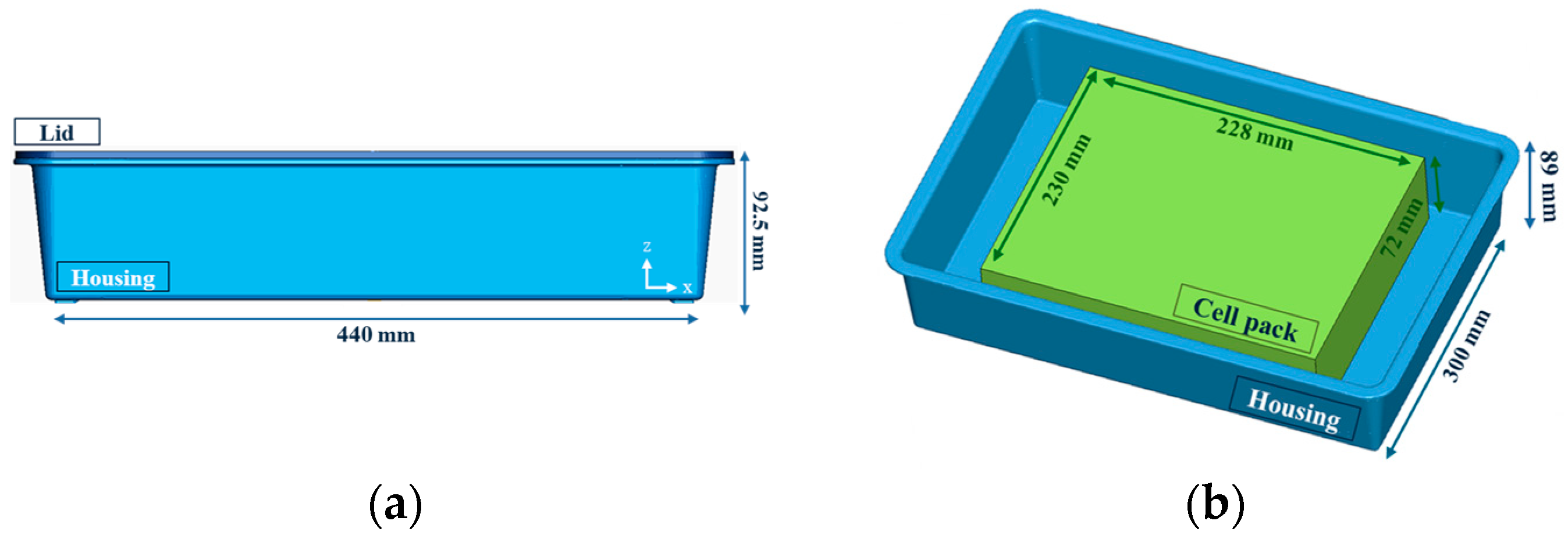
A battery system, consisting of the housing and the cell pack, presented in Figure 1, was modeled to simulate common loading conditions during transport, namely impact and vibration. The housing comprises the lid and the main enclosure, that are made from a novel composite material with a hybrid matrix, consisting of an Elium thermoplastic resin (Arkema Elium MC 590) and an aluminum hydroxide additive (Martinal ATH) to add fire resistance properties. The reinforcement consists of chopped glass fibers (JM Mulitistar 272) with a weight fraction of 20%. The material is manufactured in the form of a Sheet Molding Compound (SMC), which is a special form of prepreg that cures through compression molding. The cell pack typically incorporates the cells, the electronics (the Structural Health Monitoring system—SHM—and the Battery Monitoring System—BMS) and an additional protective plastic cover for the cells. The pack includes 5 solid-state pouch cells that weigh 0.4 kg each, and the cover is made from ABS plastic.
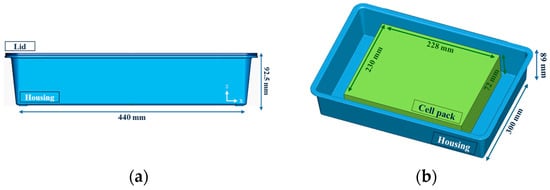
Figure 1.
The dimensions of (a) the battery housing and (b) the cell pack.
To successfully simulate the performance of the battery housing under mechanical abuse conditions, it was important to ensure the accuracy of the material parameters the battery system has; thus, it was necessary to carry out standardized mechanical tests to determine the material properties. Tests for determining the mechanical properties of the SMC material were conducted in the LTSM laboratory and the properties obtained are stated in Table 1.

Table 1.
Mechanical properties of SMC material.
3. Numerical Modeling
For the simulations, meshing was performed in Ansys Workbench and the finite element model was implemented in the LS-Dyna software. Since the focus of this study is the mechanical response of the housing, the cell pack was modeled solely as the plastic case and the additional mass of the cells. Additionally, concerning the connection between the cell pack and the housing, as well as the lid to the main enclosure, adhesive bonding is employed, which was modeled as a contact type with an incorporated failure criterion, that followed the bilinear traction–separation law, to simulate debonding (CONTACT_AUTOMATIC_SURFACE_TO_SURFACE_TIEBREAK). As for the boundary conditions, since the battery system is usually mounted on the vehicle floor, the housing was constrained perimetrically by fixing all three of the translational degrees of freedom of the support legs on the bottom surface of the system. The properties of the SMC material, obtained from the mechanical tests above, were used as inputs in material model 157 (MAT_157_ANISOTROPIC_ELASTIC_PLASTIC) of LS-Dyna, that best described the elastoplastic behavior of the thermoplastic. The same material model was used for the plastic cell cover as well, for which, bibliographic properties of ABS were selected [17].
3.1. Impact Models
The safety of the battery pack system is critical to the entire vehicle’s performance. Since the battery pack is susceptible to damage from collisions with small objects during transport, the simulation of ground impact is necessary. Explicit dynamic analysis was conducted in LS-Dyna, with a spherical steel impactor crushing the bottom surface of the housing. Three energy cases were investigated: 10, 20 and 30 J. Similarly, another impact scenario was simulated, in which a steel pole impacted the sides of the housing. Three impact velocities were studied, based on the most common speeds a vehicle is tested at in a crush test. Subsequently, the energies derived could be considered realistic.
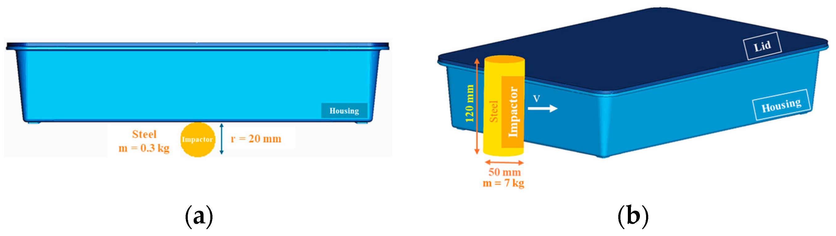
Both the ground and pole impactors, presented in Figure 2, were modeled using smoothed particle hydrodynamics (SPH), a meshless Lagrangian method that employs interpolation to calculate smooth field variables. SPH divides the domain into particles instead of elements, with assigned masses, positions and velocities, preventing mesh distortion during large deformations [18].
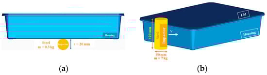
Figure 2.
Impactor geometry for (a) ground and (b) pole impact.
A Johnson–Cook material model was assigned (MAT_015_JOHNSON_COOK) and paired with the Gruneisen equation of state to describe the impactors’ thermomechanical behaviors. The velocities and impact energies of each analysis are presented in Table 2.
Table 2.
Impact cases implemented in ground and pole impact simulations.
3.2. Vibration Model
Vibration analysis is crucial when considering the dynamic response of vehicles in transport, because it identifies the resonance frequencies that can prove catastrophic to vehicle components. In order to conduct a vibration analysis, a modal one has to be executed beforehand to calculate the natural frequencies of the component. Given the natural frequencies, and by implementing an excitation load over the frequency spectrum, the resonance frequencies were identified based on the comparison between the response and the input signal.
Based on battery safety testing standards [4], three excitation signals were selected, described in Table 3 and Figure 3: sine, random and mechanical shock. Sine vibration is the most common when it comes to the identification of resonance, and random vibration is the most representative to transport vibration loads because it incorporates a noise signal as well and mechanical shock, which is designed to assess the durability of EV components under demanding conditions, such as emergency situations (e.g., sudden deceleration/acceleration).
Table 3.
Parameters of excitation loads according to battery safety standards.
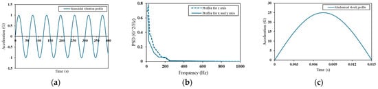
Figure 3.
Excitation loads for (a) sine vibration, (b) random vibration and (c) mechanical shock, described in battery safety standards.
The loads were applied to the housing in the finite element model by the nodes that first came in contact with the vehicle floor, and applied in the x, y and z directions. Their response was examined in the 10–1000 Hz frequency range, which is the most common range for vibration analysis.
The sine and mechanical shock signals are given by the standards in an acceleration–time form, but in order to compare them with the results of the random vibration analysis, the signals had to be transformed to the frequency spectrum which was achieved by calculating the Power Spectral Density (PSD) versus frequency curve. The time-domain signals were processed using MATLAB R2024a to obtain two calculations, the Fast Fourier Transform (FFT) and the Power Spectral Density (PSD). The FFT transforms the data into an acceleration–frequency plot. To visualize the energy distribution across the frequency spectrum, the PSD was calculated from the FFT by dividing the time-history data into equal-length frames, applying a 2n sample rate, and by calculating the FFT for each frame, squaring the individual FFTs and averaging the squared values. This results in the PSD, which is measured in G²/Hz units. Unlike the FFT, the PSD allows for the comparison of signals with different lengths without affecting the amplitude of the results [4].
4. Numerical Results
4.1. Impact Analysis Results
4.1.1. Ground Impact
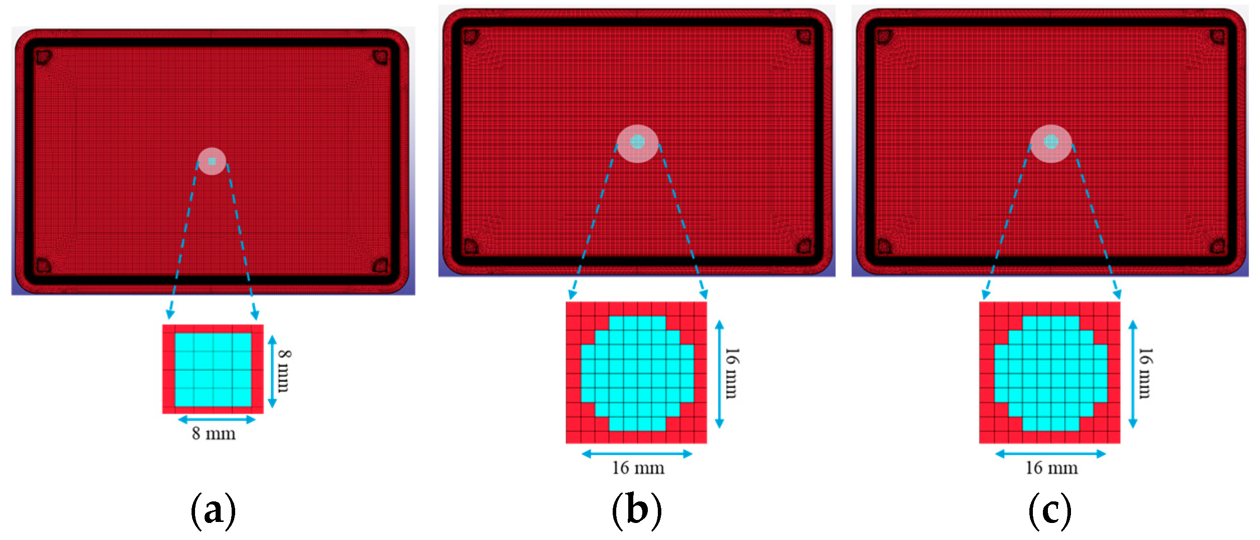
The ground impact simulations show minimal damage in all three cases. The eroded element area, presented in Figure 4, in the 10 J case is 8 by 8 mm2, with a maximum of 16 by 16 mm2 in the 20 and 30 J impact cases. The debonded areas in every scenario are less than the damaged areas, covering 36.95 mm2, 163.36 mm2 and 303.33 mm2, for 10, 20 and 30 J, respectively. The maximum z-displacements that the housing reaches due to the impact of the sphere are 2.33 mm, 3.75 mm and 5.30 mm, in each case. Essentially, the damage is a small dent on the housing’s surface, since only one row of finite elements is deleted. This is encouraging for the impact resistance of the housing, which, however, can be attributed to the presence of the cell pack, which helps with damping the impact phenomenon and is also not affected structurally by the ground impact.
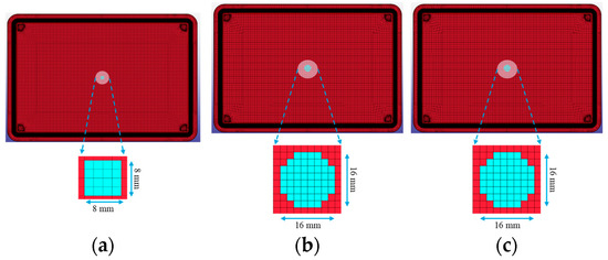
Figure 4.
Damage resulting from ground impact for (a) 10 J, (b) 20 J and (c) 30 J impact energies.
4.1.2. Pole Impact
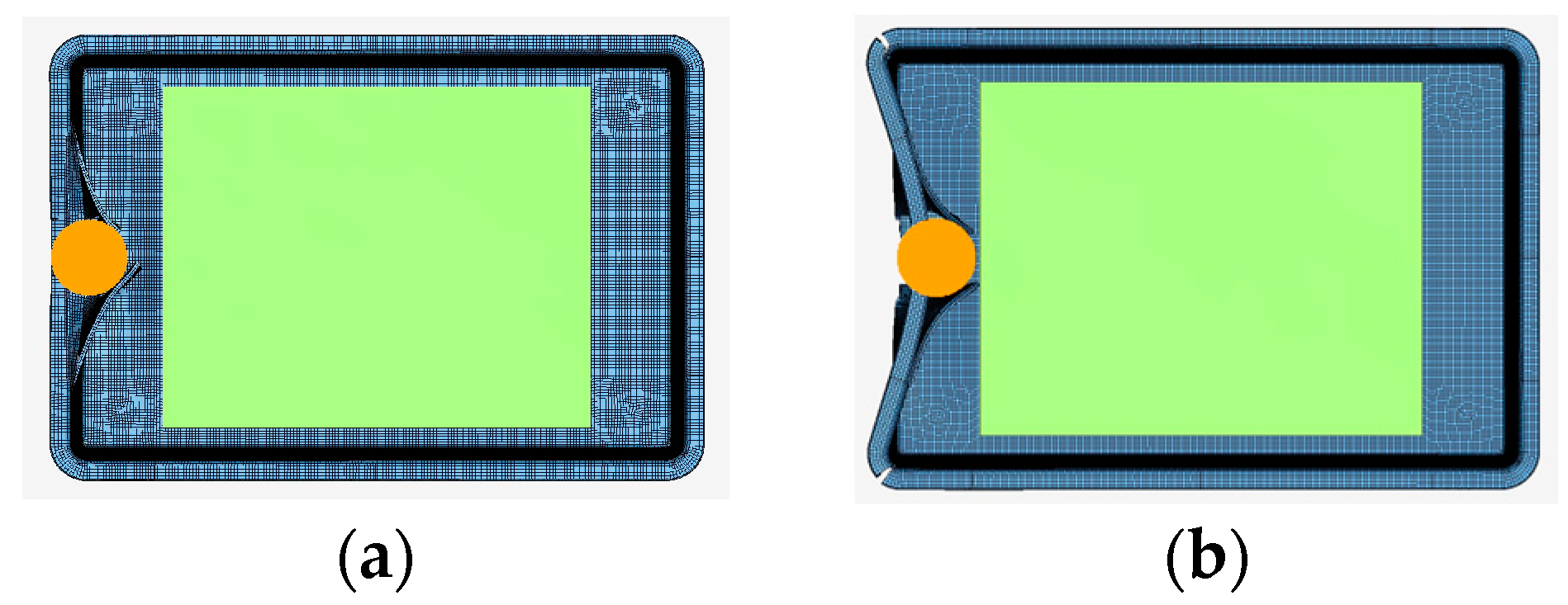
Concerning the pole impact results, from the overview of the final damage of the 350 and 787 J impact cases in Figure 5, the housing is severely damaged. The impactor deforms the left side of the housing, in every impact case, but the phenomenon is completed before it reaches the cell pack.
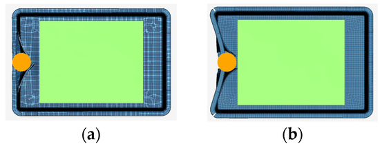
Figure 5.
Pole impact simulation results for (a) 350 J and (b) 787 J cases.
The maximum deformation of the battery enclosure is a critical factor affecting the battery’s structural integrity. While greater deformation can absorb more impact energy, it also increases the risk of battery pack damage. From the maximum displacement of the impacted areas in Figure 6, it can be deduced that there is no interference of the housing with the cell pack. Since bibliographic properties of a structural adhesive film were used to simulate the connections between the main enclosure and the lid and the cell pack and the housing, the debonded areas will not be presented; however, they are mainly concentrated in the impacted areas and the corners of the housing. Also, the cell pack is minimally debonded at the edge of the contact area.
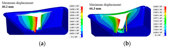
Figure 6.
Maximum displacement of impacted areas for (a) 350 J and (b) 787 J.
4.2. Modal and Vibration Analysis Results
Vehicle vibration suggests testing battery vibrational characteristics in the 0–150 Hz range for EVs and HEVs. However, standards like UN38.3, ECE 100 and SAE J2380 recommend testing in broader frequency ranges (7–200 Hz, 7–50 Hz and 10–190 Hz, respectively). This indicates that if the natural frequency of the battery and its support is above 200 Hz, vibration-induced failures may be less likely to happen [11,12]. It has also been discovered that wider vibration ranges, with frequencies above 200–300 Hz, are caused by electronic devices [19].
Concerning the modal analysis results, the first natural frequencies, up to 500 Hz, of the whole battery system, namely the housing and the cell pack, are presented in Table 4. Only two of the frequencies calculated are in the 0–200 Hz range.
Table 4.
The first 9 natural frequencies derived from the modal analysis.
For the vibration analysis results, the resonance frequencies are identified for each of the three excitation loads and each of the three directions of loading. The outcome of the analysis was evaluated by identifying the resonance through the peaks of an acceleration–frequency curve. Elements, from the FE model, of each component have been selected, based on the symmetry of the geometry, and their corresponding acceleration curves have been examined. An overview of the resonance frequencies for every loading case is presented in Table 5, and apart from a very few cases, the frequencies coincide. Additionally, most resonance frequencies are over 200 Hz, and only one resonance—98 Hz in the z-excitation—can be considered critical for transport applications. While battery cells experience vibrations in all three primary axes, the z-axis has been shown to have the most significant impact on battery performance [12].
Table 5.
The resonance frequencies derived from the vibration analysis for sine, random and mechanical shock loading in the x, y and z direction.
The results of the vibration analysis are, on one hand, a validation of the resonance frequencies, since the housing behaves similarly in every case; however, they can raise concerns, since three different loads of varying amplitudes are applied. The first reason why that happened is because the same boundary conditions were used in every loading case, since the battery system is fixed on a specific position in a vehicle. In general, vibration is very sensitive to boundary conditions, and these may change the results of the natural and resonance frequencies drastically, so the same fixture can generate the same resonance in the housing, regardless of the loading. Secondly, this may have occurred because the PSD curves have the same order of magnitude. The PSD represents the signal’s mean square amplitude over the frequency spectrum. Since the PSD–frequency curves were the inputs in the models, this means that the signal energy was distributed over the frequency range with a similar way, although the amplitude of each load in an acceleration–frequency curve is different (e.g., sine amplitude: 1 G, mechanical shock amplitude: 25 G).
5. Conclusions
To sum up, ground impact does not induce significant damage to the housing and does not influence the structural integrity of the cell pack. Pole impact resulted in severe housing deformation without compromising the cell pack. The response from the different vibration signals gives similar resonance frequencies, with most over the 200 Hz range, as commonly applied in transport. These findings suggest that this thermoplastic battery housing is suitable for transportation applications. Future research will involve experimentally validating the model and developing a structural digital twin to simulate various conditions and predict structural responses.
Author Contributions
Conceptualization, K.T.; modeling and simulations, A.F.; writing—original draft preparation, A.F.; writing—review and editing, K.T.; supervision, K.T. All authors have read and agreed to the published version of the manuscript.
Funding
This work described in this paper was financially supported by the EC-funded HORIZON Project “TEMPEST” (Project 101103681).
Institutional Review Board Statement
Not applicable.
Informed Consent Statement
Not applicable.
Data Availability Statement
Data are contained within the article.
Acknowledgments
All authors acknowledge support from Fraunhofer ICT, who provided the material samples and the CAD file of the housing to perform the mechanical tests and simulations.
Conflicts of Interest
The authors declare no conflicts of interest.
References
- Ansell, P.J. Review of sustainable energy carriers for aviation: Benefits, challenges, and future viability. Prog. Aerosp. Sci. 2023, 141, 100919. [Google Scholar] [CrossRef]
- Santosa, S.P.; Nirmala, T. Numerical and experimental validation of fiber metal laminate structure for lithium-ion battery protection subjected to high-velocity impact loading. Compos. Struct. 2024, 332, 117924. [Google Scholar] [CrossRef]
- Shaikh, S.A.; Taufique, M.F.N.; Balusu, K.; Kulkarni, S.S.; Hale, F.; Oleson, J.; Devanathan, R.; Soulami, A. Finite Element Analysis and Machine Learning Guided Design of Carbon Fiber Organosheet-Based Battery Enclosures for Crashworthiness. Appl. Compos. Mater. 2024, 31, 1475–1493. [Google Scholar] [CrossRef]
- Xing, Y.; Li, Q.M. Evaluation of the mechanical shock testing standards for electric vehicle batteries. Int. J. Impact. Eng. 2024, 194, 105077. [Google Scholar] [CrossRef]
- Avdeev, I.; Gilaki, M. Structural analysis and experimental characterization of cylindrical lithium-ion battery cells subject to lateral impact. J. Power Sources 2014, 271, 382–391. [Google Scholar] [CrossRef]
- Dai, Z.; Miao, Q.; Wu, D. Data simulation of the impact of ball strikes on the bottom of electric vehicle battery packs based on finite element analysis. Therm. Sci. Eng. Prog. 2024, 53, 102757. [Google Scholar] [CrossRef]
- Kulkarni, S.S.; Hale, F.; Taufique, M.F.N.; Soulami, A.; Devanathan, R. Investigation of Crashworthiness of Carbon Fiber-Based Electric Vehicle Battery Enclosure Using Finite Element Analysis. Appl. Compos. Mater. 2023, 30, 1689–1715. [Google Scholar] [CrossRef]
- Dhoke, A.; Dalavi, A. A Critical Review on Lightweight Design of Battery Pack Enclosure for Electric Vehicles. Int. J. Sustain. Transp. Technol. 2021, 4, 53–62. [Google Scholar] [CrossRef]
- Li, R.; Pan, Y.; Zhang, X.; Dai, W.; Liu, B.; Li, J. Mechanical safety prediction of a battery-pack system under low speed frontal impact via machine learning. Eng. Anal. Bound Elem. 2024, 160, 65–75. [Google Scholar] [CrossRef]
- Hooper, J.M.; Marco, J. Experimental modal analysis of lithium-ion pouch cells. J. Power Sources 2015, 285, 247–259. [Google Scholar] [CrossRef]
- Garafolo, N.G.; Farhad, S.; Koricherla, M.V.; Wen, S.; Esmaeeli, R. Modal Analysis of a Lithium-Ion Battery for Electric Vehicles. Energies 2022, 15, 4841. [Google Scholar] [CrossRef]
- Plaumann, B. Towards Realistic Vibration Testing of Large Floor Batteries for Battery Electric Vehicles (BEV). Sound Vib. 2022, 56, 1–19. [Google Scholar] [CrossRef]
- Hooper, J.M.; Marco, J. Understanding Vibration Frequencies Experienced by Electric Vehicle Batteries. In Hybrid and Electric Vehicles Conference 2013 (HEVC 2013); Institution of Engineering and Technology: London, UK, 2013; p. 9.1. [Google Scholar] [CrossRef]
- Xia, Y.; Wierzbicki, T.; Sahraei, E.; Zhang, X. Damage of cells and battery packs due to ground impact. J. Power Sources 2014, 267, 78–97. [Google Scholar] [CrossRef]
- Scurtu, L.; Szabo, I.; Mariasiu, F.; Moldovanu, D.; Mihali, L.; Jurco, A. Numerical analysis of the influence of mechanical stress on the battery pack’s housing of an electric vehicle. In IOP Conference Series: Materials Science and Engineering; IOP Publishing: Bristol, UK, 2019; Volume 568, p. 012054. [Google Scholar] [CrossRef]
- Wang, S.; Guo, S.; Li, R.; Hu, Z.; Leng, Q. On crashworthiness design of hybrid metal–composite battery-pack enclosure structure. Mech. Adv. Mater. Struct. 2024, 1, 1–12. [Google Scholar] [CrossRef]
- “MatWeb”. Available online: https://www.matweb.com/search/datasheet.aspx?MatGUID=3a8afcddac864d4b8f58d40570d2e5aa&ckck=1 (accessed on 4 November 2024).
- Sigalotti, L.D.G.; Klapp, J.; Gesteira, M.G. The Mathematics of Smoothed Particle Hydrodynamics (SPH) Consistency. Front. Appl. Math. Stat. 2021, 7, 797455. [Google Scholar] [CrossRef]
- Hua, X.; Thomas, A. Effect of dynamic loads and vibrations on lithium-ion batteries. J. Low Freq. Noise Vib. Act. Control 2021, 40, 1927–1934. [Google Scholar] [CrossRef]


Disclaimer/Publisher’s Note: The statements, opinions and data contained in all publications are solely those of the individual author(s) and contributor(s) and not of MDPI and/or the editor(s). MDPI and/or the editor(s) disclaim responsibility for any injury to people or property resulting from any ideas, methods, instructions or products referred to in the content. |
© 2025 by the authors. Licensee MDPI, Basel, Switzerland. This article is an open access article distributed under the terms and conditions of the Creative Commons Attribution (CC BY) license (https://creativecommons.org/licenses/by/4.0/).