Abstract
This study explored extrusion-based 3D bioprinting as a method for depositing cell-laden bio-ink to create well-defined scaffolds for tissue regeneration. Natural hydrogels, known for their biocompatibility and low cell toxicity, were favored for bio-ink formulation in this process. However, their limited mechanical strength poses a challenge to maintaining structural integrity. To address this, the rheological properties of hybrid hydrogels containing cellulose-derived nanofiber (TONFC) at concentrations between 0.5% and 1.0%, along with alginate and gelatin at levels between 2% and 5%, were tested in this study. A total of eight formulations was created by adjusting the proportions of alginate, TO-NFC, and gelatin, resulting in a combined solid content of 8%. Various rheological properties, such as the flow behavior, recovery rate, and linear viscoelastic range, were analyzed. Bi-layer scaffolds were 3D printed with various compositions and the shape fidelity was investigated. Human mesenchymal stem cells (hMSCs) were mixed to prepare bio-ink and cell survivability was observed after 7 incubation days. The ability to control 3D printability and the favorable survival of cells make nanofiber-infused alginate–gelatin a promising option for creating precisely shaped scaffolds using the 3D bio-printing process.
1. Introduction
Three-dimensional (3D) bioprinting has emerged as a groundbreaking technology in tissue engineering, offering precise control over scaffold architecture for regenerative medicine applications [1]. Out of inkjet-, laser-, and extrusion-based methods [2,3], the latter is notably adaptable, having the capability to deposit diverse types of biomaterials, including varieties of bio-ink [4]. Among the various biomaterials used in bioprinting, alginate and gelatin hold significant promise due to their favorable biocompatibility and versatility [5]. This alginate–gelatin combination was used for bioprinting with various applications such as tissue engineering and regenerative medicine [6], drug delivery [7], wound healing [8], cartilage regeneration [9], and cancer treatment [10]. Alginate, a natural polysaccharide derived from brown algae, provides excellent printability [11], while gelatin, a denatured form of collagen, offers cell-friendly environments [12]. The surface of nano-fibrillated cellulose (NFC), a derivative of cellulose gel, is altered through oxidation using 2,2,6,6 tetramethyl-1-piperidinyloxy (TEMPO) to add negatively charged carboxylate ions, which is known as TO-NFC, to improve its uniformity, dispersibility, homogeneity, and printability (TEMPO-NFC). In our earlier work, we proposed a novel bio-ink prepared with alginate, carboxymethyl cellulose (CMC), and TONFC, demonstrating the capability of 3D printing scaffolds ensuring a defined geometry and a promising cell survivability [13]. To the best of our knowledge, we are the first to introduce a novel bio-ink formulation comprising alginate, gelatin, and TO-NFC in this paper. While previous efforts have explored incorporating various fibers into alginate–gelatin compositions to enhance the scaffold’s mechanical properties [14], our approach leverages the collective advantages of all three components, aiming to achieve a precise scaffold geometry and improved cell viability during the printing process. We hypothesize that when alginate–gelatin is combined with nanofiber reinforcements, such as TEMPO-oxidized nano-fibrillated cellulose (TO-NFC), the resulting composite materials exhibit improved mechanical properties, making them an ideal choice for 3D bioprinting. In this study, we delve into the rheological properties of various compositions, incorporating alginate, gelatin, and TO-NFC at different percentages. The rheological behavior of these hybrid hydrogels is a crucial aspect to consider, as it directly impacts the printability and shape fidelity during the bioprinting process [15]. By meticulously controlling the composition ratios, we aim to fine-tune the rheological properties, ensuring optimal printability and structural integrity of the 3D-printed scaffolds. Furthermore, the incorporation of human mesenchymal stem cells (hMSCs) into the bio-ink compositions introduces an essential biological component. The potential of considering compositions for the 3D bioprinting of bio-ink can be defined by the survivability and behavior of hMSCs within the printed scaffolds. Therefore, the analysis of cell viability and proliferation within the compositions will provide valuable insights into the biocompatibility and cellular interactions of the alginate–gelatin nanofiber compositions. Through this comprehensive investigation, we aimed to establish a robust understanding of the rheological properties and cell survivability within alginate–gelatin nanofiber compositions for 3D bioprinting. The resulting outputs of this study signify the implications for advancing the field of tissue engineering, paving the way for the development of tailored therapeutic solutions for regenerative medicine applications.
2. Materials and Methods
2.1. Hybrid Hydrogel Preparation
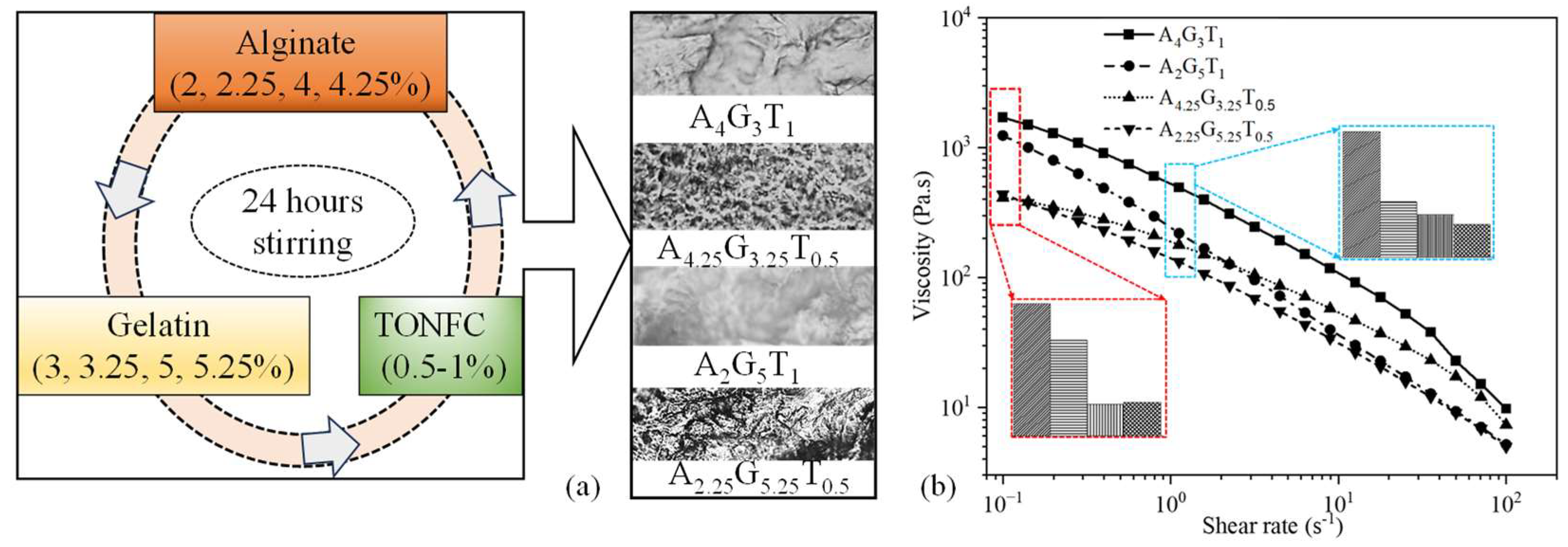
We sourced dry TEMPO nano-fibrillated cellulose (TO-NFC) [(C6H10O5)x(C6H9O4CO2Na)y] with a carboxylate level of 0.2 to 2 mmol/g solids from the Process Development Center (PDC) at the University of Maine. Medium viscous alginate (A) (viscosity ≥ 2000 cps of 2% in water) and gelatin (G) (gel strength ~300 g Bloom, 100–200 μg/cm2) (Sigma-Aldrich, St. Louis, MO, USA) were mixed with TO-NFC following a protocol depicted in Figure 1a. A total of four compositions were prepared using various percentages of A, G, and T. To reflect the impact of each element in the compositions, we chose alginate 2, 2.25, 4, and 4.25%; gelatin 3, 3.25, 5, and 5.25%; and TO-NFC 0.5 and 1%, and mixed them systematically to prepare those four compositions such as A4G3T1, A4.25G3.25T0.5, A2G5T1, and A2.25G5.25T0.5, maintaining a total solid content of 8%. All numerical subscripts represent the solid load of the component mixed into the water to prepare the material compositions.
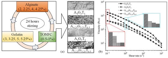
Figure 1.
(a) All compositions prepared for this paper. Compositions were stirred for 24 h to mix them uniformly. Inset figures represent the surface textures of respective composition after drying for 24 h. (b) Changes in viscosity with respect to the change in shear rate. All compositions showed shear-thinning behavior.
2.2. Rheological Analysis
We conducted rheological tests using a rheometer (MCR 102 Anton Paar, Graz, Austria) equipped with a parallel plate geometry (25.0 mm flat plate). The distance between the plates was maintained at 1.0 mm. All measurements were performed at room temperature (25 °C) to ensure that the filament solidified quickly during extrusion. To study the shear-thinning properties (0.1 to 100 s−1) we used the Power Law Equation (Equation (1)) on the section of the curve showing strain rate versus viscosity. By fitting a curve to this equation, we determined the shear-thinning coefficients n and K:
where and represent viscosity and shear rate, respectively. When extruding the material through the nozzle, there is uniform shear stress across it and it is larger along the nozzle wall. For every composition we used the curve fitting tool (Allometric) in OriginPro 2023b (Originlab, Northampton, MA, USA) to analyze the data of viscosity versus shear rate. This allowed us to determine the values of n and K. The 3D bioprinter used in this paper and related operations, such as toolpath generation and preparation of machine readable file, are discussed in our earlier article [16].
3. Results and Discussion
3.1. Flow Behavior and Shear-Thinning Coefficient
Within a total constant solid content of 8% and fixed percentages of 1% and 0.5% TO-NFC, all compositions varying in alginate and gelatin concentrations exhibited shear-thinning behavior, as the viscosity reduced with an increasing shear rate. While A4G3T1 showed the highest viscosities, A2G5T1 showed the least. The results are shown in Figure 1b. Similarly, A2.25G5.25T0.5 was lowest on the viscosity spectrum, whereas A4.25G3.25T0.5 showed the highest levels. For a constant percentage of TO-NFC (either 0.5% or 1.0%), the shear rate was mainly governed by the alginate solid load. However, with an increasing shear rate, Figure 1b shows clear evidence that the viscosity of any composition decreased with an increasing percentage of gelatin. Therefore, A2G5T1 showed a steeper reduction in viscosity, passed the viscosity of A4.25G3.25T0.5 at a 2.24 s−1 shear rate, and almost reached the viscosity of A2.25G5.25T0.5 at a 100 s−1 shear rate. Also, overall, when T1 and T0.5 are compared, compositions with T1 had higher viscosities and shear stress than those mixed with T0.5.
As mentioned in Section 2.2, for all four materials, the Power Law model was fitted to the viscosity plotted against the shear strain rate to analyze the shear-thinning coefficient. For each composition, an adjusted R-square value of more than 97% implies a good fit. The n values for A4G3T1, A4.25G3.25T0.5, A2G5T1, and A2.25G5.25T0.5 of 0.46, 0.59, 0.20, and 0.48, respectively, also confirmed that those were shear-thinning compositions. The K values for A4G3T1, A4.25G3.25T0.5, A2G5T1, and A2.25G5.25T0.5 of 514, 174, 227, and 135 Pa.s, respectively, also confirmed that even the viscosity was alginate percentage dependent, with the solid load of TO-NFC altering the viscosity substantially.
3.2. Recovery Rate
To determine the recovery rate of all the compositions after extruding the hydrogels, a three-point-interval thixotropy test (3iTT) was conducted. Before printing begins, this information is critical. The reason behind this is that it is directly related to the shape fidelity of the filament. In this test, the first interval (55–59 s) imitated the at-rest state of the sample, the second interval (60–65 s) resembled the hydrogel decomposition under high shear, i.e., hydrogel experiences high shear during extrusion, and the third interval (66–71 s) reflected the structure retention after hydrogel extrusion, as shown in Figure 2a. At 61 s, i.e., the very second the extrusion began, we observed that the viscosity significantly reduced (97%, 98%, 95%, and 96% for A4G3T1, A4.25G3.25T0.5, A2G5T1, and A2.25G5.25T0.5, respectively) due to the increment of shear rate from 1 to 100 s−1. This rapid change of shear rate broke down the initial network between all the components of each composition, converting the solid-like state of the composition to a liquid-like state that finally resulted in a smooth flow of compositions through the nozzle. After the release of the composition from the nozzle it took time to recover the internal network. Therefore, when the shear rate was reduced to 1.0 s−1 from 100 s−1, the viscosity for all the compositions was lower than at the initial stage of the test. We calculated the recovery rate after 5 s of extrusion (at 71 s) as 29%, 74%, 19%, and 26% for A4G3T1, A4.25G3.25T0.5, A2G5T1, and A2.25G5.25T0, respectively.
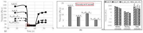
Figure 2.
(a) 3iTT tests on all compositions; (b) viscosity at 61 s, immediately after the application of pressure; and (c) recovery rate of compositions after 5 s of extrusion.
The logarithmic graph shown in Figure 1b clearly represents the changes. An interesting observation is that the composition with an initial lower viscosity showed a higher recovery rate due to the ease of finding and recovering its initial internal bonds. Therefore, A2G5T1 and A2.25G5.25T0 showed higher recovery rates (74% and 26%) compared to A4G3T1 and A4.25G3.25T0.5, which had higher initial viscosities. There is a high chance that material with lower initial viscosities will demonstrate over-deposition with the same applied pressure, which will result in poor shape fidelity. Therefore, the application-based (either good cell viability or better shape fidelity) material can be selected depending on the initial viscosity and recovery rate.
3.3. Analysis of 3D Printed Filament
All four compositions were extruded with the application of air pressure. The materials started flowing depending on the shear-thinning capacity provided by the amount of applied pressure. The diffusion rate, such as the rate of material spread with respect to the nozzle diameter, was determined for all compositions, as shown in Figure 3a. Even the K values followed a sequence of A4G3T1 > A2G5T1 > A4.25G3.25T0.5 > A2.25G5.25T0.5, while the diffusion rate showed a slightly different sequence of A4G3T1 > A4.25G3.25T0.5 > A2G5T1 > A2.25G5.25T0.5. This phenomenon can be explained with Figure 3a, where A4.25G3.25T0.5 shows a higher viscosity than A2G5T1 during extrusion, i.e., with the application of air pressure. This means that, during extrusion, A2G5T1 spreads more than A4.25G3.25T0.5, resulting in a higher diffusion rate. Acellular bi-layer scaffolds were fabricated with all compositions using a similar air pressure (120 kPa), as shown in Figure 3b. Among the four compositions, A4G3T1 showed a better printability with a proper pore size and geometry. Even though A2G5T1 showed a higher diffusion rate, due to its quick recovery rate (74%) it was able to preserve the pore geometry. Due to the rough filament created by A2G5T1, the pore sizes were not uniform. The pore geometry of the scaffold printed with A4.25G3.25T0.5 was not preserved due to it having the lowest recovery rate (19%).
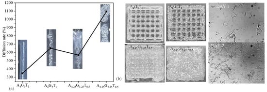
Figure 3.
(a) Diffusion rate of 3D-printed filament and (b) scaffolds using A4G3T1, A2G5T1, A4.25G3.25T0.5, and A2.25G5.25T0.5. Scaffold size was 20 mm × 20 mm. (c) hMSCs’ survivability after mixing with A5G2T1 compositions after 7 incubation days.
On the other hand, the pore geometry of the scaffold printed with A2.25G4.25T0.5 was not preserved due to it having the lowest viscosity among the four compositions. Another phenomenon was identified during extrusion: the presence of higher gelatin may create a non-uniform distribution of all components and make the filament and scaffold surface rough during extrusion. Therefore, with the considered conditions, A4G3T1 can be used as an optimum composition for 3D bioprinting to obtain a predefined scaffold architecture. In future, we will extrude with various extrusion pressure other than 120 kPa to explore the controllability of the diffusion rate of various compositions with respect to the applied pressure.
3.4. Cell Survivability
Normal human adipose-derived mesenchymal stem cells (hMSCs) (ATCC, Manassas, VA, USA) were cultured and maintained in a Stem Cell Growth Kit for Adipose and umbilical-derived MSCs-Low Serum (2% FBS, 5 ng/mL rh FGF basic, 5 ng/mL rh FGF acidic, 5 ng/mL rh EGF, 2.4 mM L-Alanyl-L-Glutamine) with additional 0.5 mL Penicillin–Streptomycin–Amphotericin B Solution (ATCC, Manassas, VA, USA). Cells were incubated in 5% CO2 at 37 °C. The culture medium was changed twice a week. Cells in passage 3 were used for encapsulation. Images were captured using a CK Olympus bright field microscope (Tokyo, Japan). As a sample composition, we considered A5G2T1 and mixed cells into this material to identify the survivability. From Figure 3c, it is clear that cells were alive with the presence of this material composition and increased their number as the incubation day increased from day 1 to day 7.
4. Conclusions and Discussion
In this research, we explored the rheological properties and printability of a set of hybrid hydrogels composed with alginate, gelatin, and TO-NFC. To identify the impact of each component, we maintained a constant solid load percentage of 8%. Experimental data showed that alginate and TO-NFC had a greater impact than gelatin in the regulation of the viscosity of the compositions during extrusion. Therefore, with a close look at the 3iTT test, we identified that there was a sequence of viscosity of A4G3T1 > A4.25G3.25T0.5 > A2G5T1 > A2.25G5.25T0.5 during extrusion. This indicates that a higher percentage of the combined alginate and TO-NFC (A + T: 5, 4.75, 3, 2.75) exhibits greater resistance to shear stress compared to gelatin (G: 3, 3.5, 5, 5.25) alone. This behavior, along with the difference in the recovery rate, helps explain the diffusion rate of filaments and pore closure events of each scaffold fabricated with all compositions. Building upon these outcomes and considering the extreme printing conditions employed in prior studies [17], we observed that hMSCs could survive in one of the compositions considered in this paper.
Author Contributions
A.H. conceived the idea. R.S. conducted the characterization tests, and B.S. conducted the 2D and 3D cell cultures. All authors have read and agreed to the published version of the manuscript.
Funding
This research was supported by New Hampshire-EPSCoR through BioMade Award #1757371 from the National Science Foundation and New Hampshire-INBRE through an Institutional Development Award (IDeA), P20GM103506, from the National Institute of General Medical Sciences of the NIH.
Institutional Review Board Statement
Not applicable.
Informed Consent Statement
Not applicable.
Data Availability Statement
Data are contained within the article.
Acknowledgments
Department of Sustainable Product Design and Architecture, Keene State College, Keene, NH and Department of Manufacturing and Mechanical Engineering Technology of Rochester Institute of Technology.
Conflicts of Interest
Authors declare no conflict of Interest.
References
- Deo, K.A.; Singh, K.A.; Peak, C.W.; Alge, D.L.; Gaharwar, A.K. Bioprinting 101: Design, fabrication, and evaluation of cell-laden 3D bioprinted scaffolds. Tissue Eng. Part A 2020, 26, 318–338. [Google Scholar] [CrossRef] [PubMed]
- Murphy, S.V.; Atala, A. 3D bioprinting of tissues and organs. Nat. Biotechnol. 2014, 32, 773–785. [Google Scholar] [CrossRef] [PubMed]
- He, Y.; Yang, F.; Zhao, H.; Gao, Q.; Xia, B.; Fu, J. Research on the printability of hydrogels in 3D bioprinting. Sci. Rep. 2016, 6, 29977. [Google Scholar] [CrossRef] [PubMed]
- Ji, S.; Guvendiren, M. Recent advances in bioink design for 3D bioprinting of tissues and organs. Front. Bioeng. Biotechnol. 2017, 5, 23. [Google Scholar] [CrossRef] [PubMed]
- Di Giuseppe, M.; Law, N.; Webb, B.; Macrae, R.A.; Liew, L.J.; Sercombe, T.B.; Dilley, R.J.; Doyle, B.J. Mechanical behaviour of alginate-gelatin hydrogels for 3D bioprinting. J. Mech. Behav. Biomed. Mater. 2018, 79, 150–157. [Google Scholar] [CrossRef] [PubMed]
- Ruther, F.; Distler, T.; Boccaccini, A.; Detsch, R. Biofabrication of vessel-like structures with alginate di-aldehyde—Gelatin (ADA-GEL) bioink. J. Mater. Sci. Mater. Med. 2019, 30, 8. [Google Scholar] [CrossRef] [PubMed]
- Mirek, A.; Belaid, H.; Barranger, F.; Grzeczkowicz, M.; Bouden, Y.; Cavaillès, V.; Lewińska, D.; Bechelany, M. Development of a new 3D bioprinted antibiotic delivery system based on a cross-linked gelatin–alginate hydrogel. J. Mater. Chem. B 2022, 10, 8862–8874. [Google Scholar] [CrossRef] [PubMed]
- Liu, J.; Chi, J.; Wang, K.; Liu, X.; Liu, J.; Gu, F. Full-thickness wound healing using 3D bioprinted gelatin-alginate scaffolds in mice: A histopathological study. Int. J. Clin. Exp. Pathol. 2016, 9, 11. [Google Scholar]
- Schwarz, S.; Kuth, S.; Distler, T.; Gögele, C.; Stölzel, K.; Detsch, R.; Boccaccini, A.R.; Schulze-Tanzil, G. 3D printing and characterization of human nasoseptal chondrocytes laden dual crosslinked oxidized alginate-gelatin hydrogels for cartilage repair approaches. Mater. Sci. Eng. C 2020, 116, 111189. [Google Scholar] [CrossRef]
- Jiang, T.; Munguia-Lopez, J.G.; Flores-Torres, S.; Grant, J.; Vijayakumar, S.; Leon-Rodriguez, A.D.; Kinsella, J.M. Directing the Self-assembly of Tumour Spheroids by Bioprinting Cellular Heterogeneous Models within Alginate/Gelatin Hydrogels. Sci. Rep. 2017, 7, 4575. [Google Scholar] [CrossRef] [PubMed]
- Axpe, E.; Oyen, M.L. Applications of alginate-based bioinks in 3D bioprinting. Int. J. Mol. Sci. 2016, 17, 1976. [Google Scholar] [CrossRef] [PubMed]
- Carlström, I.E.; Rashad, A.; Campodoni, E.; Sandri, M.; Syverud, K.; Bolstad, A.I.; Mustafa, K. Cross-linked gelatin-nanocellulose scaffolds for bone tissue engineering. Mater. Lett. 2020, 264, 127326. [Google Scholar] [CrossRef]
- Habib, M.; Khoda, B. Fiber Filled Hybrid Hydrogel for Bio-Manufacturing. J. Manuf. Sci. Eng. 2020, 143, 041013. [Google Scholar] [CrossRef]
- Luo, W.; Song, Z.; Wang, Z.; Wang, Z.; Li, Z.; Wang, C.; Liu, H.; Liu, Q.; Wang, J. Printability optimization of gelatin-alginate bioinks by cellulose nanofiber modification for potential meniscus bioprinting. J. Nanomater. 2020, 2020, 3863428. [Google Scholar] [CrossRef]
- Tuladhar, S.; Clark, S.; Habib, A. Tuning Shear Thinning Factors of 3D Bio-Printable Hydrogels Using Short Fiber. Materials 2023, 16, 572. [Google Scholar] [CrossRef] [PubMed]
- Habib, A.; Sarah, R.; Tuladhar, S.; Khoda, B.; Limon, S.M. Modulating rheological characteristics of bio-ink with component weight and shear rate for enhanced bioprinted scaffold fidelity. Bioprinting 2024, 38, e00332. [Google Scholar] [CrossRef]
- Li, H.; Tan, Y.J.; Leong, K.F.; Li, L. 3D bioprinting of highly thixotropic alginate/methylcellulose hydrogel with strong interface bonding. ACS Appl. Mater. Interfaces 2017, 9, 20086–20097. [Google Scholar] [CrossRef] [PubMed]


Disclaimer/Publisher’s Note: The statements, opinions and data contained in all publications are solely those of the individual author(s) and contributor(s) and not of MDPI and/or the editor(s). MDPI and/or the editor(s) disclaim responsibility for any injury to people or property resulting from any ideas, methods, instructions or products referred to in the content. |
© 2024 by the authors. Licensee MDPI, Basel, Switzerland. This article is an open access article distributed under the terms and conditions of the Creative Commons Attribution (CC BY) license (https://creativecommons.org/licenses/by/4.0/).