Abstract
The paper presents a compact dual-band pentagonal-shaped patch antenna, with resonating frequencies 7.6 GHz and 12 GHz, that is used for satellite communication, 5G application, and high-speed applications. The proposed antenna is designed on an FR4 substrate with an overall dimension of 16 × 16 mm where the height of the substrate is 0.8 mm. The proposed antenna contains a pentagonal-shaped patch with four circles at each corner of the patch that is used for the dual-band; in addition, the circular slot with the combination of the cross-shaped slot achieves better results. The proposed antenna has a partial ground configuration for better bandwidth and gain. The peak gain of the antenna is 8.07 dB at 12 GHz and has a 7.13 dB gain at 7.6 GHz. With its compact size and wide bandwidth capabilities, the antenna proves to be an ideal solution for mobile communication systems, satellite ground stations, and remote sensing applications across C-, X-, and Ku-bands. The proposed antenna also covers Ku used for satellite and high-speed communication.
1. Introduction
The microstrip patch antenna is widely used in communication and electronic systems. It is a form of printed circuit antenna that is designed to be thin, light, and low profile. Microstrip patch antennas consist of a radiating sheet of conductive material, typically copper or gold, that is printed into a dielectric substrate [1]. The emitting patch is then excited by a feed line that is connected to the patch through a small gap or hole. Microstrip patch antennas possess several notable advantages. One of their primary benefits lies in their low-profile design, which allows for compact installations in devices and systems with limited physical dimensions. This characteristic makes microstrip patch antennas an excellent choice for portable and handheld devices. Their low profile enables installations in space-constrained environments, while their lightweight construction and cost-effective manufacturing process contribute to their wide usability [2]. Their frequency, agility, and ease of integration make them suitable for various electronic systems, and their design flexibility allows for customization to meet specific requirements.
Dual-band microstrip patch antennas are a variety of antennas capable of simultaneously functioning at two distinct frequencies. Their versatility proves valuable in scenarios demanding multiple frequencies, including satellite communications, wireless networks, and radar systems [3]. These antennas are specifically designed to efficiently transmit and receive signals in both frequency bands, facilitating seamless communication across various channels. Their compact size, lightweight nature, and ease of integration make them highly desirable for environments with limited space and portable devices. Moreover, the partial ground configuration of these antennas guarantees improved performance and radiation characteristics. Dual-band microstrip patch antennas provide a dependable and effective solution for addressing the requirements of contemporary wireless communication systems [4].
The Ku-band, widely used in satellite communication for DTH services, broadcasting, and broadband Internet access, excels in high transmission rates and efficient conveyance of large data volumes over long distances, enabling seamless and reliable communication for diverse applications [5]. With its widespread adoption and exceptional performance, the Ku-band continues to revolutionize the way information is transmitted and received across vast geographical regions. Leveraging the Ku-band with the GPS enhances precision, particularly in urban regions where signal strength tends to be compromised.
The constant progress in wireless communication technologies has sparked the need for antennas that can effectively operate within specific frequency bands. This paper introduces an innovative antenna design that provides coverage for both the C and X frequency bands, enabling a diverse array of applications in wireless systems. The C and X frequency bands have garnered substantial interest due to their distinct characteristics and extensive utilization across various domains [6]. The C frequency band, spanning from approximately 4 to 8 GHz, finds extensive application in satellite communications, enabling long-distance transmission and broadcasting, making it an indispensable tool for global communication networks, and it is also utilized in weather radar systems, enabling meteorologists to monitor atmospheric conditions, detect storms, and provide accurate forecasts [7]. It also finds application in short-range communication systems like satellite navigation, radio astronomy, and wireless LANs.
This research endeavors to address the increasing demand for versatile wireless communication systems by developing an antenna that covers both the C and X frequency bands, unlocking a wide range of possibilities in satellite communications, weather monitoring, defense and military systems, and space exploration. Subsequent sections will provide detailed insights into the antenna design, performance evaluation, and prospects of this innovative solution [8]. Overall, the research highlights the efficacy of circular microstrip patch antennas in fulfilling the demands of high-power applications across the C-, X-, and Ku-bands. The suggested antenna design holds the potential for implementation in diverse wireless communication systems, such as satellite communication, point-to-point communication, and 5G cellular networks. Some of the latest designs are also discussed in [9,10]. In this paper, we first provide an introduction and an overview of related research, which discussed the C- and Ku-bands, that was carried out recently. Then, we describe the design of the antenna in Section 2, which includes how we can improve and make changes in the antenna. After that, we discuss the results in Section 3 of a parametric analysis that is presented in the paper. The comparison of the different results is also discussed in this section. Finally, we conclude the paper by summarizing the key findings and offering insights into future research directions.
2. Design of Antenna
After making modifications to the initial design and optimizing its performance through a series of four steps, we successfully developed an improved antenna that yields superior results, holding promise for delivering enhanced functionality and meeting specific requirements in various applications. The evolution of the antenna is discussed in four different steps given below.
2.1. Step 1 Antenna
The antenna is simulated using HFSS (high-frequency Simulation software) with an overall dimension of 16 × 16 mm2. The proposed antenna consists of a pentagonal-shaped patch with a full ground configuration. The design of the first-step antenna is shown in Figure 1a.
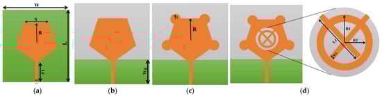
Figure 1.
Antenna design: (a) step 1, (b) step 2, (c) step 3, (d) step 4.
2.2. Step 2 Antenna
In the second step, the full ground configuration of the proposed antenna is converted into a partial ground configuration while the other parameters of the antenna remain the same. The length of the ground and the design of the second-step antenna is shown in Figure 1b.
2.3. Step 3 Antenna
Now, we have a pentagonal-shaped patch with a partial ground configuration. In this stage, four circles are attached to each corner of the pentagonal-shaped patch while the fifth one is attached to the feedline. The design of the antenna is shown in Figure 1c.
2.4. Step 4 Antenna
The proposed antenna is designed on an FR4 substrate (εr = 4.4) with a thickness of 0.8 mm and a loss tangent of 0.02. In the final stage, a ring shape with a cross-shaped structure is added at the center of the patch, which is used for better results [11]. The proposed antenna has a partial ground configuration. The antenna has a peak gain of 8.05 dB at 12 GHz and a 7.13 dB gain at 7.6 GHz. The proposed antenna covers C-, X-, and Ku-bands which are used for satellite and high-speed communication. The proposed antenna is dual-band and operates at two different frequencies: 7.6 GHz, and 12 GHz. The pentagonal-shaped patch is used for higher gain while the small four circles are used for better bandwidth. The ring structure in the patch is used to obtain the desired frequency band. The design and dimension of the proposed antennas are shown in Figure 1d and Table 1, respectively.

Table 1.
Design antenna parameter values.
3. Results
S-parameters, also known as dispersion parameters, are a set of complex numbers that describe the behavior of an antenna in a microwave circuit. There are four S-parameters, S11, S12, S21, and S22, which represent the reflection coefficient, forward transfer coefficient, reverse transfer coefficient, and load impedance matching factor.
In the given scenario, the antenna operates in the C- and X- and Ku-bands and has an operating frequency of 7.6 GHz and 12 GHz, as shown in Figure 2. The bandwidth of the antenna is 840 MHz at the operating frequency of 7.6 GHz, and the bandwidth is 890 MHz at the operating frequency of 12 GHz. The return loss of the antenna is measured at −30.25 dB, representing the amount of energy reflected from the source due to a mismatch between the antenna and the transmission line or load. Return loss assesses power transfer efficiency in the antenna and transmission system. A value of −30.25 dB indicates a good impedance match, with only a small portion of the transmitted energy being reflected. This suggests that the antenna has been matched well to the transmission line, enabling efficient energy transfer and improved signal transmission while minimizing signal loss. Achieving a good impedance match is crucial for maximizing antenna performance by ensuring that most of the transmitted energy is radiated and not wasted as reflected power. A high return loss value demonstrates an efficient operation of the antenna within the given transmission system or load conditions, achieved through minimized reflections and optimized power transfer. VSWR (voltage standing wave ratio) is a measure of the mismatch between the impedance of an antenna and the transmission line to which it is connected [12]. A VSWR of 1:1 means a perfect match, while a higher value means a mismatch.
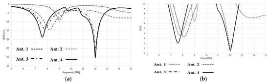
Figure 2.
Simulated results: (a) S-parameters (b) VSWR.
In this case, the VSWR of the antenna is given as 0.565 at a frequency of 12 GHz, as shown in Figure 2b. This means that there is a mismatch between the antenna and the transmission line, and the reflected signal has a magnitude of 0.565 times the forward signal. The combined VSWR of the different antennae is shown in Figure 3. Antenna gain is a measure of the antenna’s ability to direct or focus radiated energy in a specific direction. It is usually expressed in decibels (dB) relative to an isotropic radiator (a theoretical antenna that radiates equally in all directions) [13]. In this case, we obtained the antenna gain at two different frequencies: 7.13 dB at 7.6 GHz and 8.07 dB at 12 GHz. This means that the antenna has a higher gain at a higher frequency. Also, the gain of the proposed antenna is greater than the previous antenna discussed in this paper.
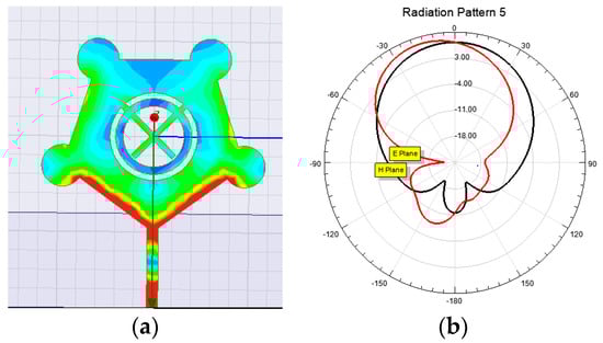
Figure 3.
(a) Current Distribution (b) E- and H-plane.
Antenna gain is a function of several factors, including the physical dimensions of the antenna, the shape of the antenna, and the frequency of operation. In general, as the frequency of operation increases, antenna gain tends to decrease unless special measures are taken to increase the gain at higher frequencies. The current distribution and E- and H-plane of the proposed antenna are shown in Figure 3a and Figure 3b, respectively.
4. Conclusions
In conclusion, the pentagonal-shaped dual-band antenna’s exceptional versatility enables effective operation on 7.6 GHz and 12 GHz frequencies, making it highly suitable for many communication applications in C-, X-, and Ku-band spectra. The pentagonal-shaped dual-band antenna’s versatility in supporting multiple frequency bands eliminates the need for separate antennas or complex systems, streamlining communication setups and reducing costs. Moreover, the proposed antenna has an acceptable gain of 8 dB at its operating frequency of 12 GHz, which makes it useful in high-gain applications. The pentagonal-shaped dual-band antenna, with its practicality, adaptability, dual-band capability, unique shape providing omnidirectional radiation patterns, cost-effectiveness, and versatility, proves to be an ideal choice for industries reliant on efficient and high-performing communication systems, particularly in the domains of satellite and mobile communication, offering reliable signal transmission in all directions.
Author Contributions
Conceptualization, M.Z. and M.M.T.; methodology, M.M.T.; software, M.M.T.; validation, M.Z.; writing—original draft preparation, M.M.T.; writing—review and editing, Y.A. All authors have read and agreed to the published version of the manuscript.
Funding
This research received no external funding.
Institutional Review Board Statement
Not applicable.
Informed Consent Statement
Not applicable.
Data Availability Statement
The data can be obtained from the corresponding author on request.
Conflicts of Interest
The authors declare no conflict of interest.
References
- Parasuraman, S.; Yogeeswaran, S.; Ramesh, G.P. Design of Microstrip Patch Antenna with improved characteristics and its performance at 5.1 GHz for Wireless Applications. IOP Conf. Ser. Mater. Sci. Eng. 2020, 925, 012005. [Google Scholar] [CrossRef]
- Singh, S.; Singla, B.S.; Sharma, M.; Goyal, S.; Sabo, A. Comprehensive Study on Internet of Things (IoT) and Design Considerations of Various Microstrip Patch Antennas for IoT Applications. In Mobile Radio Communications and 5G Networks: Proceedings of MRCN 2020; Springer: Singapore, 2021. [Google Scholar]
- Samsuzzaman, M.; Islam, M.T.; Misran, N.; Mohd Ali, M.A. Dual-band X shape microstrip patch antenna for satellite applications. Procedia Technol. 2013, 11, 1223–1228. [Google Scholar] [CrossRef]
- Chakraborty, U.; Kundu, A.; Chowdhury, S.K.; Bhattacharjee, A.K. Compact dual-band microstrip antenna for IEEE 802.11 a WLAN application. IEEE Antennas Wirel. Propag. Lett. 2014, 13, 407–410. [Google Scholar] [CrossRef]
- Malisuwan, S.; Sivaraks, J.; Madan, N.; Suriyakrai, N. Design of microstrip patch antenna for Ku-band satellite communication applications. Int. J. Comput. Commun. Eng. 2014, 3, 413. [Google Scholar] [CrossRef]
- Chinnagurusamy, B.; Perumalsamy, M.; Sarasam, A.S.T. Design and fabrication of compact triangular multiband microstrip patch antenna for C-and X-band applications. Int. J. Commun. Syst. 2021, 34, e4939. [Google Scholar] [CrossRef]
- Haque, A.; Paul, L.C.; Azim, R.; Mowla, M.; Saleh, A.; Hossain, N. A Modified E-Shaped Microstrip Patch Antenna for C Band Satellite Applications. In Proceedings of the 2019 IEEE International Conference on Signal Processing, Information, Communication & Systems (SPICSCON), Dhaka, Bangladesh, 28–30 November 2019. [Google Scholar]
- Verma, R.K.; Srivastava, D.K. Bandwidth improvement of stub loaded compact ultra-wideband microstrip patch antenna for C/X-band applications. Wirel. Pers. Commun. 2021, 120, 185–202. [Google Scholar] [CrossRef]
- Felicia, I.E.; Gomathi, V.; Paulraj, E.I. Two-Port UWB-MIMO Antenna Design for WiMAX and X-Band Applications. In Proceedings of the 2023 International Conference on Recent Trends in Electronics and Communication (ICRTEC), Mysore, India, 10–11 February 2023; pp. 1–7. [Google Scholar] [CrossRef]
- Arshad, M.A.; Zahid, M.; Amin, Y.; Jaffer, S.S. MIMO Antenna for C-band Applications. In Proceedings of the 2023 International Multi-Disciplinary Conference in Emerging Research Trends (IMCERT), Karachi, Pakistan, 4–5 January 2023; pp. 1–5. [Google Scholar] [CrossRef]
- Karthika, K.; Anusha, K. A Novel Compact Slotted Pentagon Shaped Patch Antenna for Ultra-Wideband Applications. In Proceedings of the 2021 International Conference on Advancements in Electrical, Electronics, Communication, Computing, and Automation (ICAECA), Coimbatore, India, 8–9 October 2021. [Google Scholar]
- Rana, S.; Rahman, M. Study of microstrip patch antenna for a wireless communication system. In Proceedings of the 2022 International Conference for Advancement in Technology (ICONAT), Goa, India, 21–22 January 2022. [Google Scholar]
- Mohammed, A.S.; Kamal, S.; Bin Ain, M.F.; Najmi, F.; Ahmad, Z.A.; Zahar, Z.; Hussin, R.; Zubir, I.A.; Ab Rahman, M. Improving the gain performance of air substrate patch antenna array using the effect of conductive material thickness study for 5G applications. J. Phys. Conf. Ser. 2020, 1529, 052020. [Google Scholar] [CrossRef]
Disclaimer/Publisher’s Note: The statements, opinions and data contained in all publications are solely those of the individual author(s) and contributor(s) and not of MDPI and/or the editor(s). MDPI and/or the editor(s) disclaim responsibility for any injury to people or property resulting from any ideas, methods, instructions or products referred to in the content. |
© 2023 by the authors. Licensee MDPI, Basel, Switzerland. This article is an open access article distributed under the terms and conditions of the Creative Commons Attribution (CC BY) license (https://creativecommons.org/licenses/by/4.0/).