Abstract
The high load capacity and the harsh working environment of mining dump trucks require suspension structures with good damping properties and simple structures. Hydro-pneumatic suspensions are widely used due to their non-linear stiffness and damping characteristics, which allow them to adapt to changes in external load excitation. To solve the problem of the high stiffness of the vehicle under loading impact conditions, which leads to easy damage to the suspension and tire components, a two-stage pressure hydro-pneumatic suspension system is designed to meet the needs of the new vehicle based on the single-chamber hydro-pneumatic suspension. The 1/4 hydro-pneumatic suspension of a mining dump truck is applied as the research object. By comparing the pressure, dynamic deflection, and acceleration of the two types of suspension cylinders through simulation and experiment, respectively, the damping characteristics of the two-stage pressure hydro-pneumatic suspension system during the loading process are obtained.
1. Introduction
Hydro-pneumatic suspensions are widely used on off-highway vehicles due to their variable stiffness and variable damping characteristics. The working environment of mining dump trucks is harsh, and the impact on the vehicle during operation can cause serious damage to the hydro-pneumatic suspension and tire components.
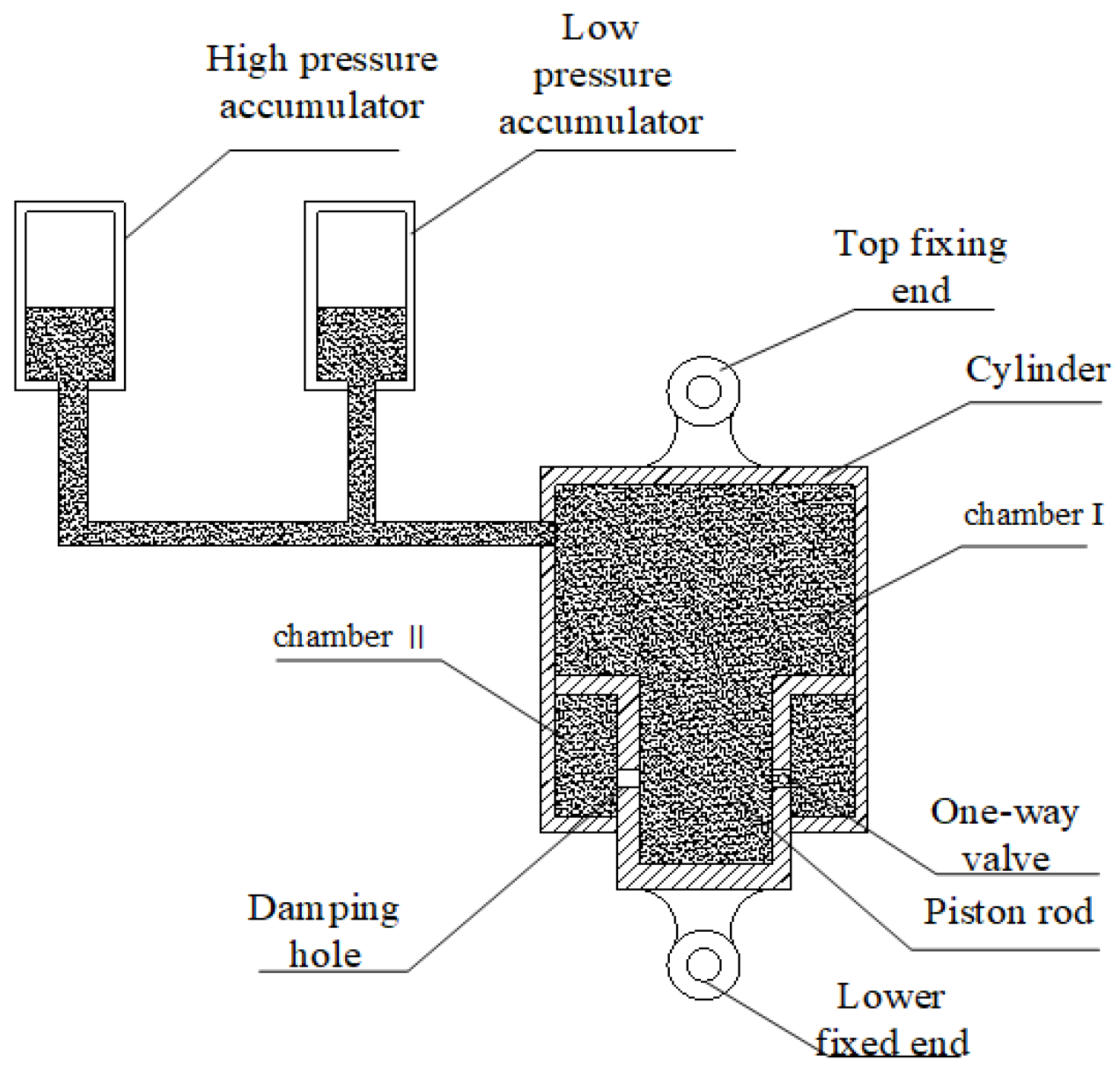
To improve the overall service life of the vehicle, this paper designs a two-stage pressure-type hydro-pneumatic suspension system and studies its damping characteristics under loading conditions [1]. A new type of two-stage pressure-type hydro-pneumatic suspension for mining dump trucks produced by a company is used as the research object. The single-chamber and two-stage pressure hydro-pneumatic systems are modeled by AMESim software, and the damping characteristics of the single-chamber hydro-pneumatic suspension and two-stage pressure hydro-pneumatic suspension in the loading process are analyzed through simulation and experimental comparison [2]. The two chambers of the two-stage pressure chamber hydro-pneumatic suspension do not participate in the work at the same time; when the spring load is not large, the main chamber acts alone, and the air pressure of the main chamber gradually increases with the increase of the load; when the pressure of the main chamber is greater than the air pressure of the compensation chamber, the two chambers will work at the same time, so as to ensure that the vehicle has the same inherent vibration frequency at no load and full load. Figure 1 shows a sketch of the structure of the two-stage pressure hydro-pneumatic suspension.
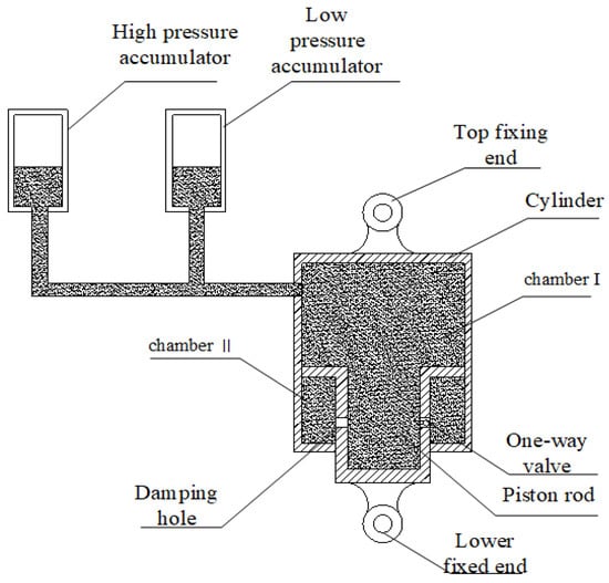
Figure 1.
Schematic diagram of two-stage pressure hydro-pneumatic suspension structure.
When the suspension is in compression working, the piston and the piston rod move upward relative to the cylinder barrel, at this time, the volume of oil chamber I becomes smaller and the pressure becomes larger. The volume of oil chamber II becomes larger and the pressure becomes smaller, the check valve opens, and the hydraulic oil inside oil chamber I is compressed to flow in two directions, part of the hydraulic oil flows into oil chamber II through the check valve and the damping hole. The other part of the hydraulic oil flows into the low-pressure accumulator through the rubber hose, so that the accumulator gas chamber is compressed, the volume becomes smaller and the pressure rises. When the pressure reaches the initial pressure of the high-pressure accumulator, the high-pressure accumulator opens and the hydraulic oil flows into the high-pressure accumulator through the rubber hose [3].
2. Development and Analysis of the Mathematical Model of Hydro-Pneumatic Suspension
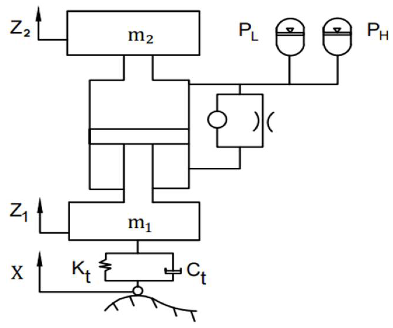
The hydro-pneumatic suspension starts to work when the vehicle passes over road obstacles as shown in Figure 2, a mathematical model of the single-wheel two degrees of freedom vibration of a heavy vehicle suspension system is established. This model only considers the vibration of the suspension in the vertical direction and ignores the vibration of the other degrees of freedom. The equations of motion for the suspended and non-suspended masses are obtained from the mathematical model as follows.
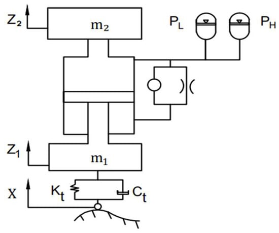
Figure 2.
Mathematical model of two-stage pressure hydro-pneumatic suspension.
3. Hydro-Pneumatic Suspension Modeling and Simulation Using AMESim
In the AMESim simulation software, a two-stage pressure hydro-pneumatic suspension model was constructed based on the single air chamber as shown in Figure 3. The simulation model was created based on the actual structural parameters of a mining dump truck and the main parameters are shown in Table 1.
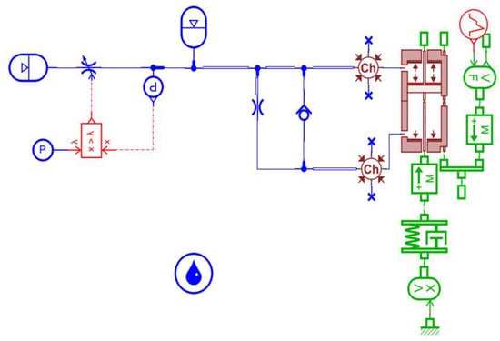
Figure 3.
Two-stage pressure hydro-pneumatic suspension model.

Table 1.
Hydro-pneumatic suspension model parameters.
3.1. Simulation Analysis and Experimental Comparison
The pressure and displacement sensors were installed on the oil and gas suspension during the experiments and the mounting positions are shown in Figure 4. The pressure and displacement information of the suspension was obtained by means of the DEWE-2600 multi-channel data acquisition instrument [4,5].
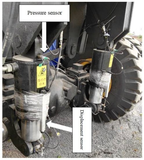
Figure 4.
Sensors installation position.
The experimental vehicle is the newly developed TLD110 mining dump truck from Shaanxi Tongli Heavy Industries, with a body weight of 40 tones and a load capacity of 70 tons, having a total weight of 110 tons at full load.
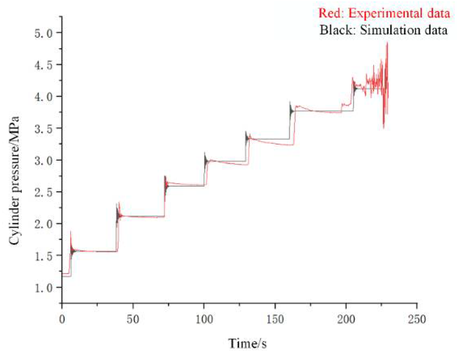
To verify the correctness of the simulation analysis, the oil density and oil temperature during the simulation are consistent with the actual experiment. To exclude the factor of self-weight of the body to be considered during the experiment, the simulation model was first run unloaded for 30 s to make the system reach static equilibrium, and then seven times 10 tons of loading excitation was input one by one to obtain the pressure change curve of the suspension cylinder accumulator as shown in Figure 5. As can be seen from the graph, the cylinder pressure oscillation peak is becoming smaller and smaller, which is due to the vehicle stiffness becoming higher and higher during the loading process in the experiment, the uneven loading mass, the drop position, and offset of the center of gravity of the loaded material [6,7]. The maximum relative error between the simulation data value and the experimental test value of the single air chamber hydro-pneumatic suspension is 5.70%, which is within a reasonable range and verifies the accuracy of the simulation model [8,9].
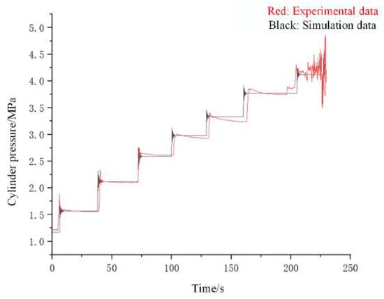
Figure 5.
Pressure characteristic curve of hydro-pneumatic suspension.
3.2. Characteristic Analysis
3.2.1. Pressure Characteristic Analysis
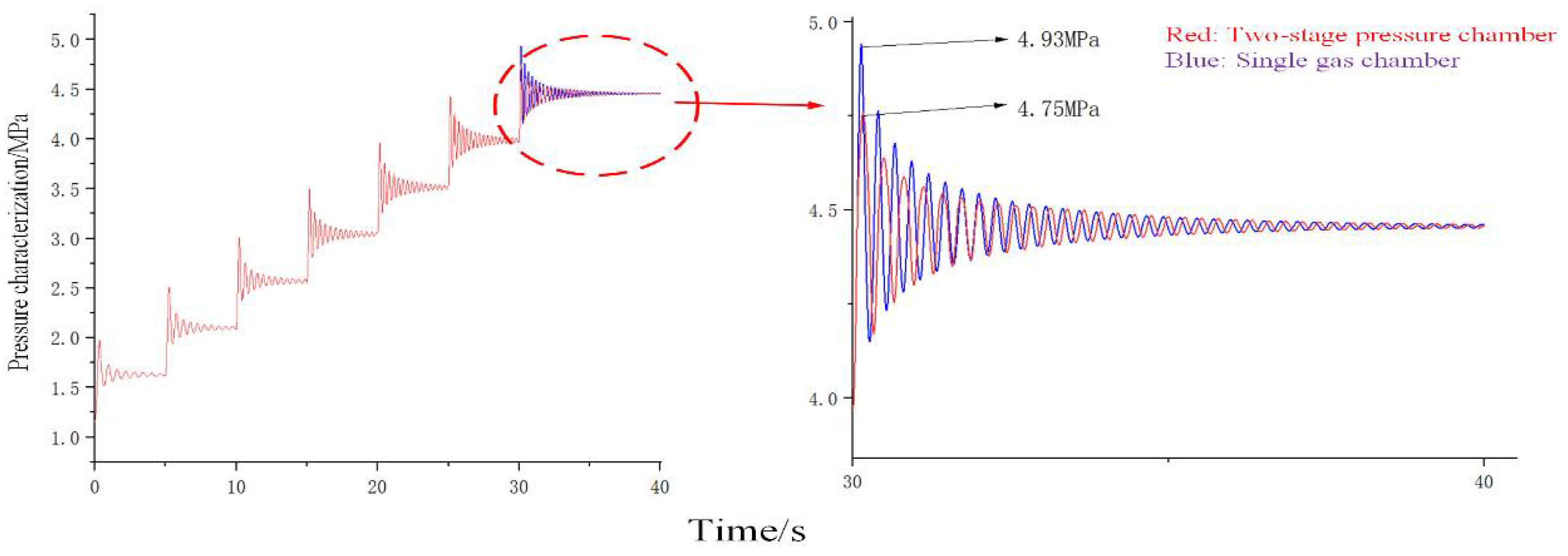
The hydro-pneumatic suspension pressure characteristic curve is shown in Figure 6. The cylinder pressure did not reach the high-pressure accumulator opening pressure during the first six loadings, the high-pressure accumulator of the two-stage pressure type did not work at this time, and the cylinder pressure reached high-pressure accumulator opening pressure during the seventh loading, and the high-pressure accumulator worked. From the graph, the peak pressure of the cylinder of the single-chamber hydro-pneumatic suspension is 4.93 MPa, and the peak pressure of the cylinder of the two-stage pressure hydro-pneumatic suspension is 4.75 MPa, the peak pressure of the cylinder of the new hydro-pneumatic suspension is reduced by 0.18 MPa [10,11]. Then, the cylinder pressure changes of both suspensions tend to be close to each other, which indicates that the two-stage pressure hydro-pneumatic suspension is more responsive and can protect the suspension better.
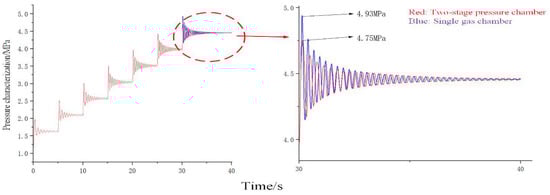
Figure 6.
Variation curve of cylinder pressure.
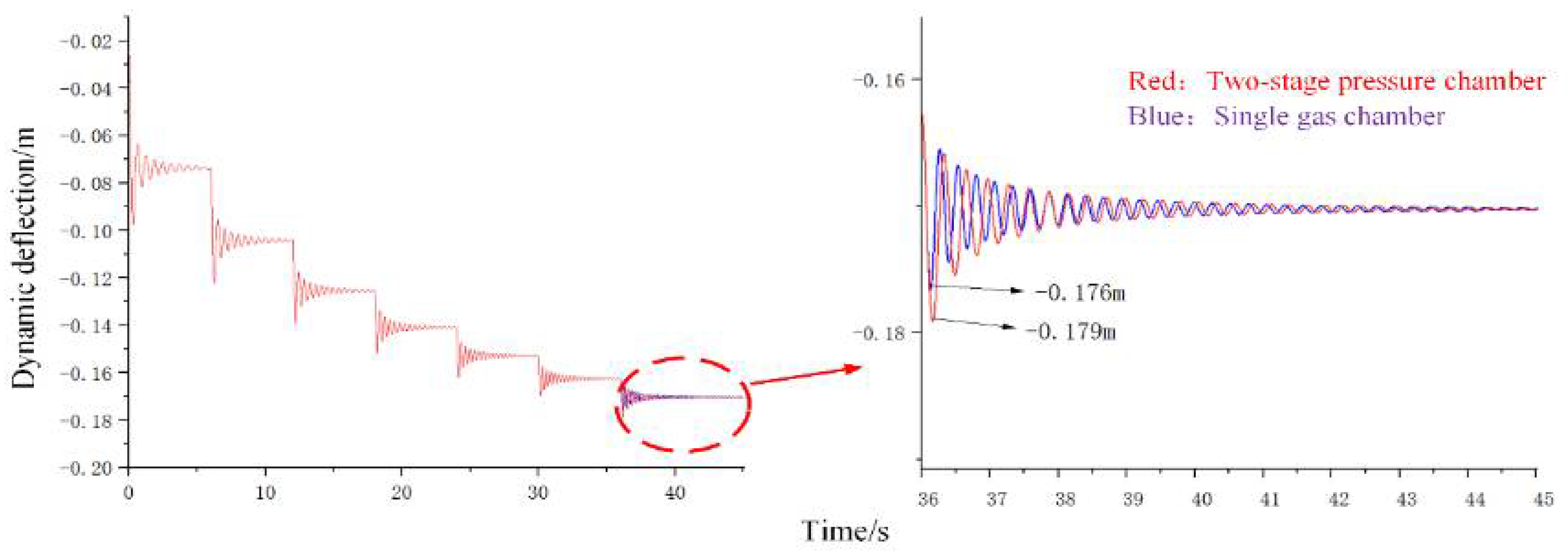
3.2.2. Dynamic Deflection Characteristics Analysis
The dynamic deflection characteristics of the hydro-pneumatic suspension piston concerning the cylinder barrel are shown in Figure 7. The two-stage pressure high-pressure accumulator did not work during the first six loadings, and the high-pressure accumulator worked during the seventh loading.
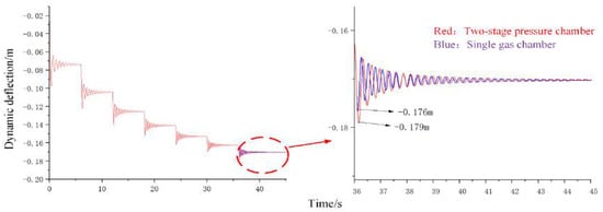
Figure 7.
Variation curve of dynamic deflection.
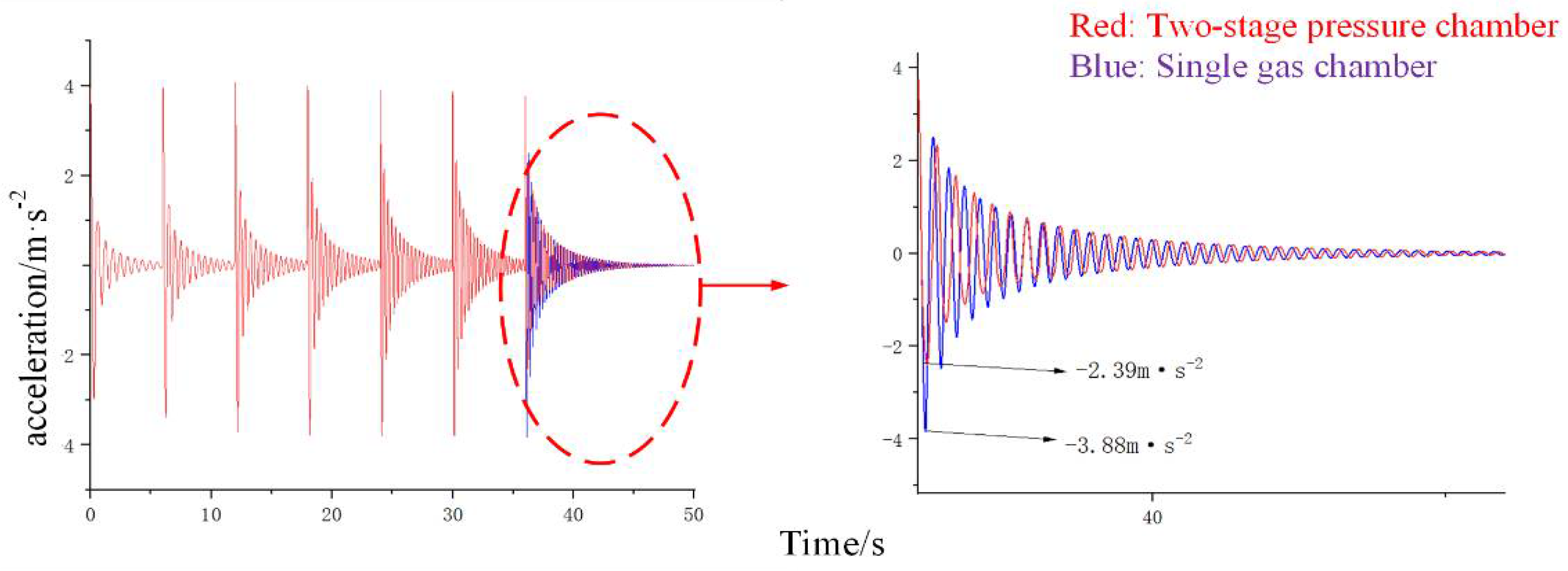
3.2.3. Acceleration Analysis
The acceleration changes curve of the oil and gas suspension is shown in Figure 8. The two-stage pressure high-pressure accumulator did not work during the first six loadings, and the high-pressure accumulator worked with the seventh load. As can be seen from the figure, the acceleration peak of the two-stage pressure hydro-pneumatic suspension is decreased by 62.3%, compared with the single-chamber hydro-pneumatic suspension of −3.88 m·s−2.
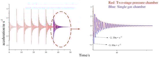
Figure 8.
Variation curve of acceleration.
4. Conclusions
A two-stage pressure hydro-pneumatic suspension was designed based on the original single chamber hydro-pneumatic suspension, and the output characteristics of the hydro-pneumatic suspension system were analyzed and studied under vehicle loading impact. The following results can be obtained from simulation and experiment analysis: (1) the peak pressure of the cylinder of the improved two-stage pressure hydro-pneumatic suspension is reduced by 0.18 Mpa; (2) the maximum displacement of the piston compression stroke of the new two-stage pressure hydro-pneumatic suspension increases by 3 mm during the loading shock, and the two-stage pressure hydro-pneumatic suspension system is more conducive to stabilizing the body under the same excitation. The simulation and test analysis proved that the two-stage accumulator system is effective in improving the impact resistance and smoothness and stability of heavy vehicles.
Author Contributions
Conceptualization, G.W.; methodology, G.W. and X.S.; software, Y.Z. and X.L.; formal analysis, Y.Z. and X.L.; writing—original draft preparation, Y.Z.; funding acquisition, G.W. and X.S. All authors have read and agreed to the published version of the manuscript.
Funding
This work was supported, in part, by the Natural Science Basic Research Project of Shaanxi Province, China (Grant No. 2019JM-073).
Institutional Review Board Statement
Not applicable.
Informed Consent Statement
Not applicable.
Data Availability Statement
No new data were created or analyzed in this study. Data sharing is not applicable to this article.
Conflicts of Interest
The authors declare no conflict of interest.
References
- Liu, H.B. Performance Parameters Effect Analysis of Interconnected Hydro-pneumatic Suspension Based on AMESim. Mach. Tool Hydraul. 2017, 45, 130–136. [Google Scholar]
- Liu, J.Q.; Wang, Y.C.; Wang, C.Z. Study on Stiffness Characteristics of Interconnected Hydro-pneumatic Suspension System with Inclined Suspension Cylinders. Mach. Tool Hydraul. 2019, 47, 59–63. [Google Scholar]
- Suo, X.F.; Jiao, S.J.; Wang, G.F. Experimental Study on Vibration and Impact Characteristics of Hydro-pneumatic Suspension of a Mine Dump Truck. Noise Vib. Control 2020, 40, 173–176+240. [Google Scholar]
- Ma, L.Z. Research on Ride Comfort of Multi-Axle Emergency Rescue Vehicle. Yan Shan Univ. 2021, 27, 13–27. [Google Scholar]
- Sun, C.B.; Ma, D.W.; Zhu, Z.L. Vibration performance of interconnected hydro-pneumatic suspension based on the damping assembly at different positions. J. Mach. Des. 2015, 32, 34–40. [Google Scholar]
- Sun, Y.B. Research on Characteristics of Hybrid-interconnected Hydro-pneumatic Suspension and Analysis of Ride Comfort. Dalian Univ. Technol. 2016, 57, 32–39. [Google Scholar]
- Tian, W.P.; Yang, Y.K.; Wang, W. The Influence of the Interconnection Forms of Hydro-pneumatic Suspension on Vehicle Stability. Automot. Eng. 2017, 39, 1362–1367+1389. [Google Scholar]
- Wang, S.; Fang, Q.; Zhang, L.J. Research on the Influence of Electric Hydraulic Damper on the Ride Comfort of Tracked Vehicle. Veh. Power Technol. 2021, 3, 21–27. [Google Scholar]
- Wei, Z.L.; Xiu, X.; Zhuang, X.Y. Design of Hydro Pneumatic Spring Balanced Suspension System for Heavy Trailer. Intern. Combust. Engine Parts 2021, 20, 1–2. [Google Scholar]
- You, Z.; He, R.; Liu, W.G. Performance Analysis of Hydro-Pneumatic Suspension of Truck Based on Stiffness and Damping Characteristics. Mach. Des. Manuf. 2022, 373, 223–227. [Google Scholar]
- Zhang, L.; Liu, Q.S.; Wang, Z.P. Electro-hydraulic Brake Control for Improved Ride Comfort in Four-wheel-independently-actuated Electric Vehicles. J. Mech. Eng. 2020, 56, 125–134. [Google Scholar]


Publisher’s Note: MDPI stays neutral with regard to jurisdictional claims in published maps and institutional affiliations. |
© 2022 by the authors. Licensee MDPI, Basel, Switzerland. This article is an open access article distributed under the terms and conditions of the Creative Commons Attribution (CC BY) license (https://creativecommons.org/licenses/by/4.0/).