Abstract
Switched-mode power supply and semiconductor devices have been gaining more and more applicability in the industrial scenario. With the massive use of these devices, several problems related to power quality and equipment degradation have been arising, caused mainly by the harmonic content present in current and voltage. Power quality problems have direct implications for business productivity, causing high economic losses. Therefore, it is mandatory to develop solutions that mitigate these problems. Active power filters (APF) are power electronic equipment capable of compensating power quality problems. Moreover, it presents the ability to dynamically adjust their modes of operation in response to changes in load or the power systems. Active power filters present the economical advantage of using the same current and voltage sensors already existing in a power system. Aiming to develop an APF for single-phase applications, this work proposes a shunt controlled active power filter using hall effect current and voltage sensor, aiming to compensate harmonic currents provided by nonlinear loads. It was proposed two proportional-integral compensators, where the external loop is responsible for link-CC control and the inner loop is responsible for current compensation. The results show the applicability of the proposed APF, since all harmonic content was filtered.
1. Introduction
The advent of power electronics allowed the improvement of semiconductor devices, generating a crucial change in the drive, control and power level of various types of loads. Therefore, power electronic systems are used increasingly in a wide range of application fields, such as variable-speed drives, switched sources, rectifiers, and others. Moreover, they are widely used for administrative equipment such as personal computers [1]. However, power semiconductor devices bring, as a disadvantage, the appearance of harmonics in the electrical grid [2]. These harmonics are originated by the non-linear conduction of the electronic switches, causing distortions in the voltage and current waveform. Due to this non-linear current, the system has to supply a large amount of reactive power [3].
In this context, grid harmonics cause problems, such as voltage regulation and stability, deterioration of power quality, and increasing system losses. Due to the enormous financial and operational impact caused by the presence of reactive energy in the grid, the correct control and mitigation of reactive power and harmonic are more than necessary topics nowadays [4,5].
To solve problems related to loads with high harmonic content, active power filters (APFs) [6] are used. APFs are used to compensate current distortions from non-linear loads. This is accomplished by injecting harmonic currents into the grid as phase opposition to the harmonic currents generated by the load [7]. In addition, active power filters present the economical advantage of using the same current and voltage sensors already existing in power systems [8].
In this context, this work proposes a shunt controlled active power filter using Hall effect current and voltage sensor aiming to mitigate harmonic current content from non-linear loads. To achieve this goal, a non-linear load (emulated through a rectifier) was powered by a single-phase voltage supply. At the common coupling point, a shunt active power filter, consisting of a DC bus and four semiconductor switches (IGBT) switches, was set in parallel with the load. The proposed control system for the switching of the electronic devices was achieved through the acquisition of the current and voltage signals from the grid by the hall effect sensors. Furthermore, two proportional-integral compensators were proposed, where the external loop is responsible for link-DC control, and the inner loop is responsible for current compensation. Harmonic mitigation was achieved by assessing these current and voltage signals from hall effect sensors in the proposed AFP. This control technique allows the compensation of currents generated by non-linear loads.
In conclusion, based on the relevance of the power electronics devices in the industrial scenario, it is crucial to develop systems capable to mitigate reactive power and harmonic content [9]. Furthermore, the control algorithm proposed in this work proved to be an efficient technique for the APF system. The hall effect sensors applied to signal acquisition are considerably useful, due to their applications in power systems, allowing the development of viable active power filters. Finally, the results showed the applicability of the proposed APF, since all harmonic content was filtered.
2. Hall Effect Sensors
A Hall effect sensor is a transducer that, when under application of a magnetic field, responds with a variation in its output voltage [10].
The Hall effect is a property that manifests itself in a conductor when a magnetic field perpendicular to the current flow is applied on it. When this occurs, a voltage in the conductor is generated, called Hall voltage. This voltage has a perpendicular direction to the magnetic field and current, and is proportional to the magnetic flux density and current. The magnetic field applied causes a gradient of carrier concentration in the entire conductor. When the number of carriers on one side of the conductor is greater than the other, then this voltage will appear. Hall voltage amplitude varies with current and magnetic field [10].
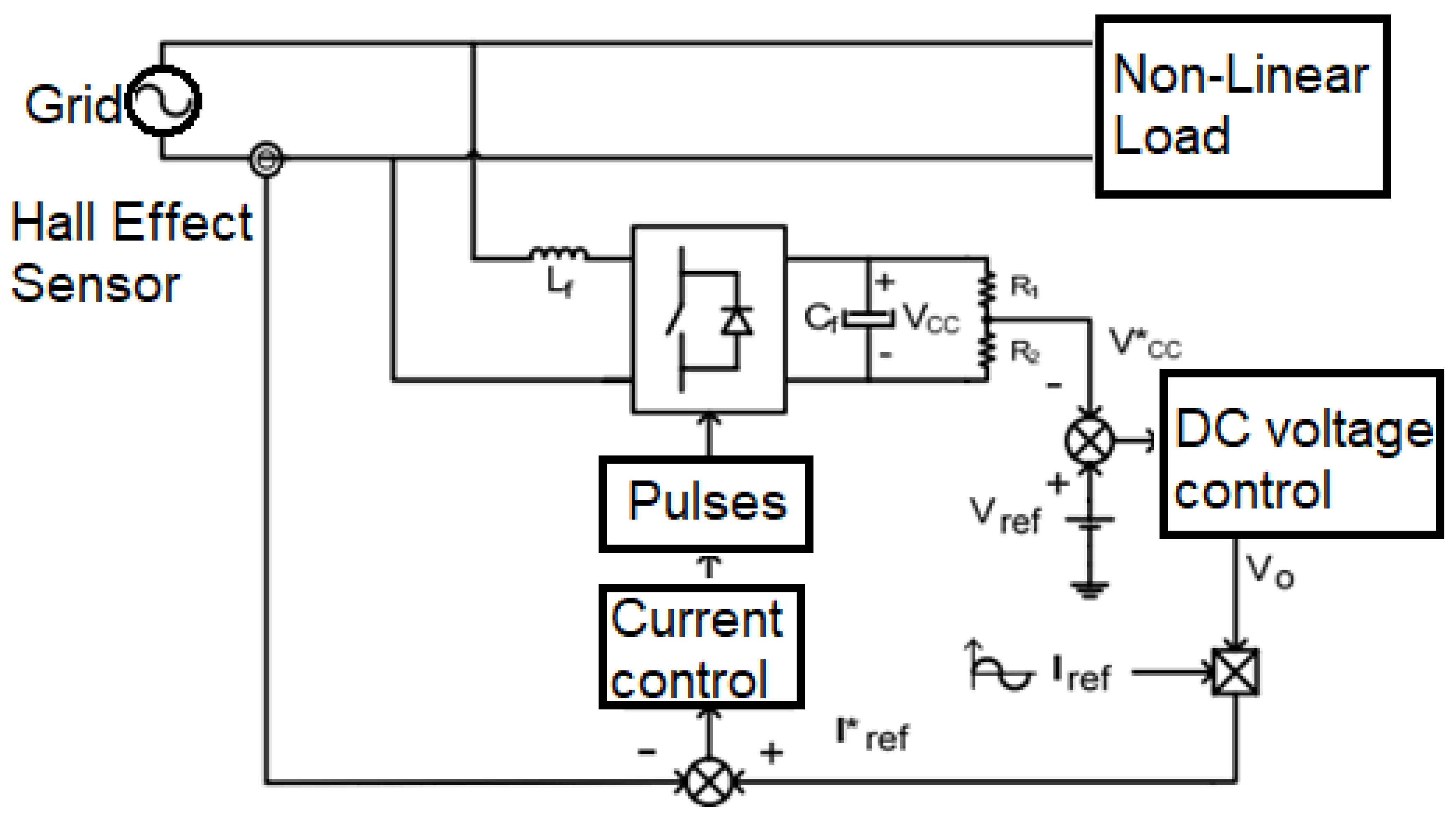
3. Control Technique
The control algorithm developed in this article is based on the proportional-integral compensators. The following subsections will present the active power filter and the control algorithm.
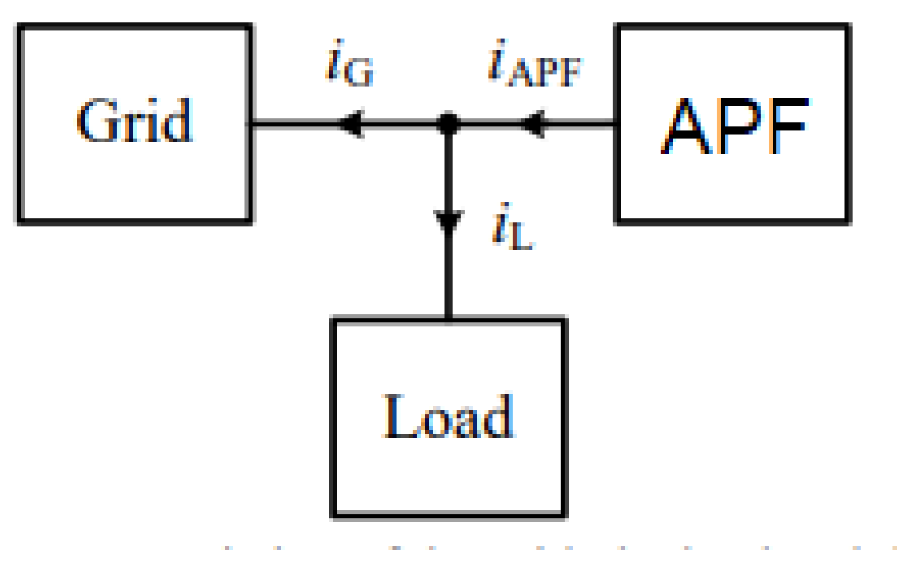
3.1. Active Power Filter
The active power filter consists of injecting compensation currents into the electrical grid in order to cancel the harmonic and reactive power generated by the load. The main goal of the APF is that the currents of the load and the currents of the active power filter result in sinusoidal grid currents, i.e., no harmonic content [7]. A typical system setup is shown in Figure 1.
Figure 1.
Active Power Filter.
The structure chosen for the assembly of the active power filter was the full bridge voltage source inverter. This topology consists of four semiconductor switches (IGBT) and a DC bus.
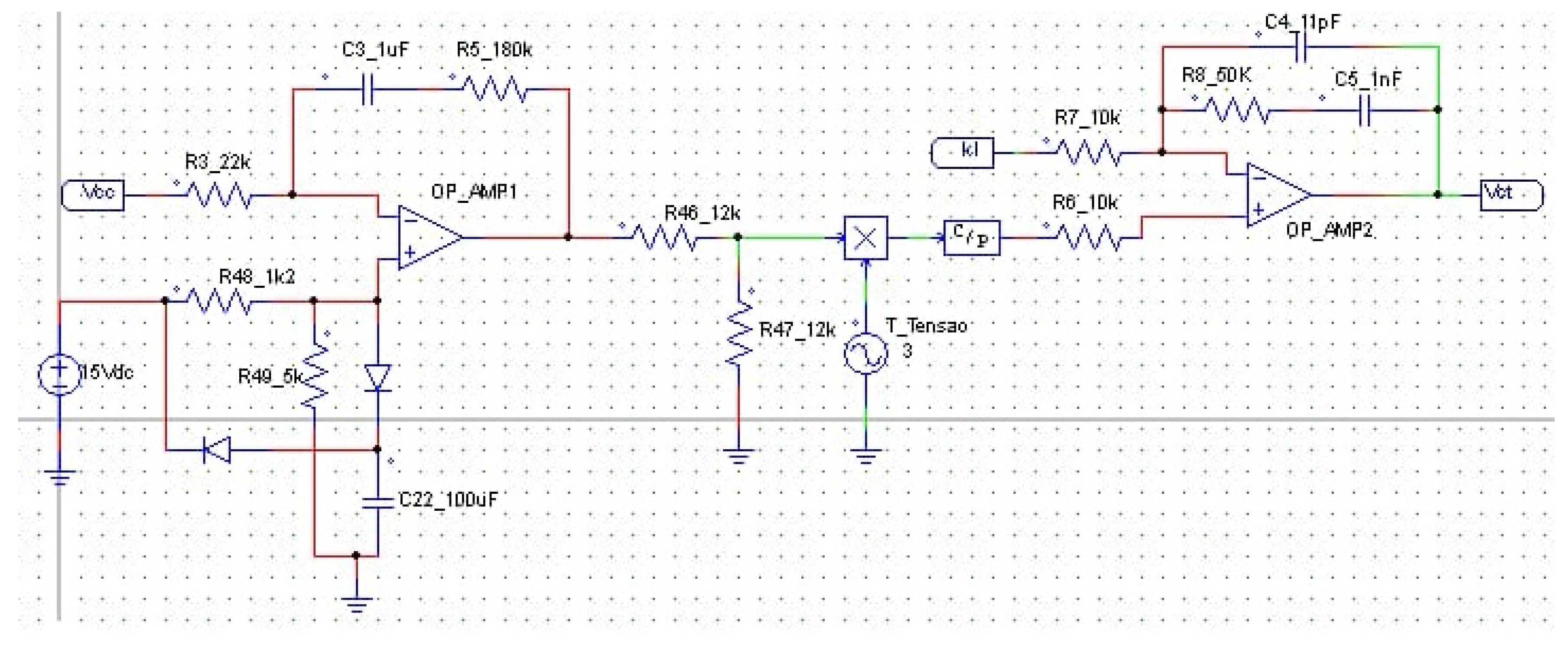
3.2. Control Algorithm
The proposed control algorithm is based on two proportional-integral compensators, where the external loop is responsible for link-DC control and the inner loop is responsible for current compensation. The block diagram of the control system is shown in Figure 2.
Figure 2.
Control Algorithm Block Diagram.
The control system was designed according to the experimental assembly specifications shown in the following section. For the practical implementation of the proportional-integral controller, operational amplifiers were used. With this, the external loop has the function of controlling the DC bus voltage at a specific value and providing the current reference for the internal loop. This loop aims to generate the necessary pulses for switching IGBT devices, mitigating current harmonics. The structure of the proportional-integrated controllers, and its values are presented in Figure 3.
Figure 3.
Proportional-Integral Design.
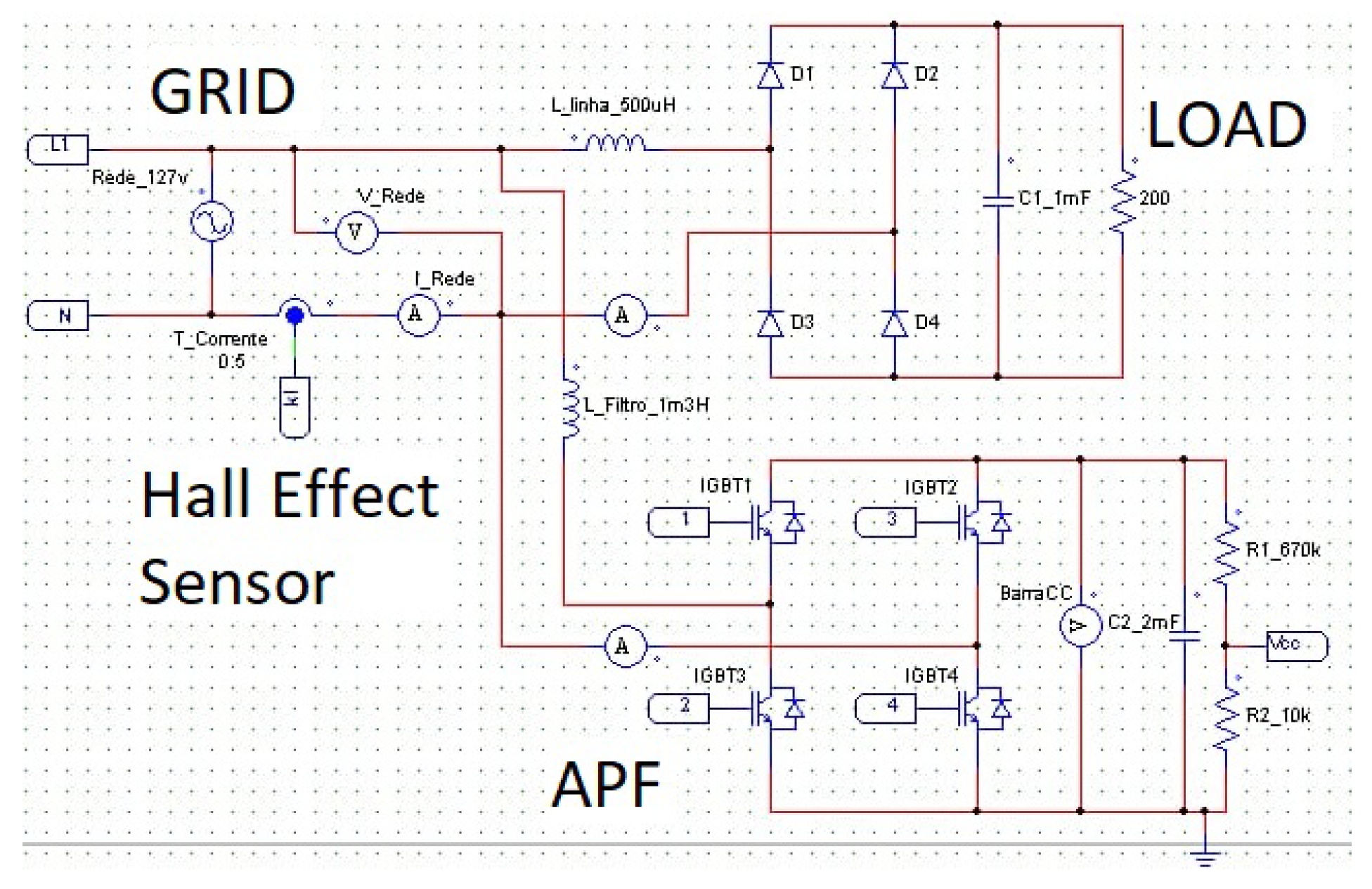
4. Experimental Setup
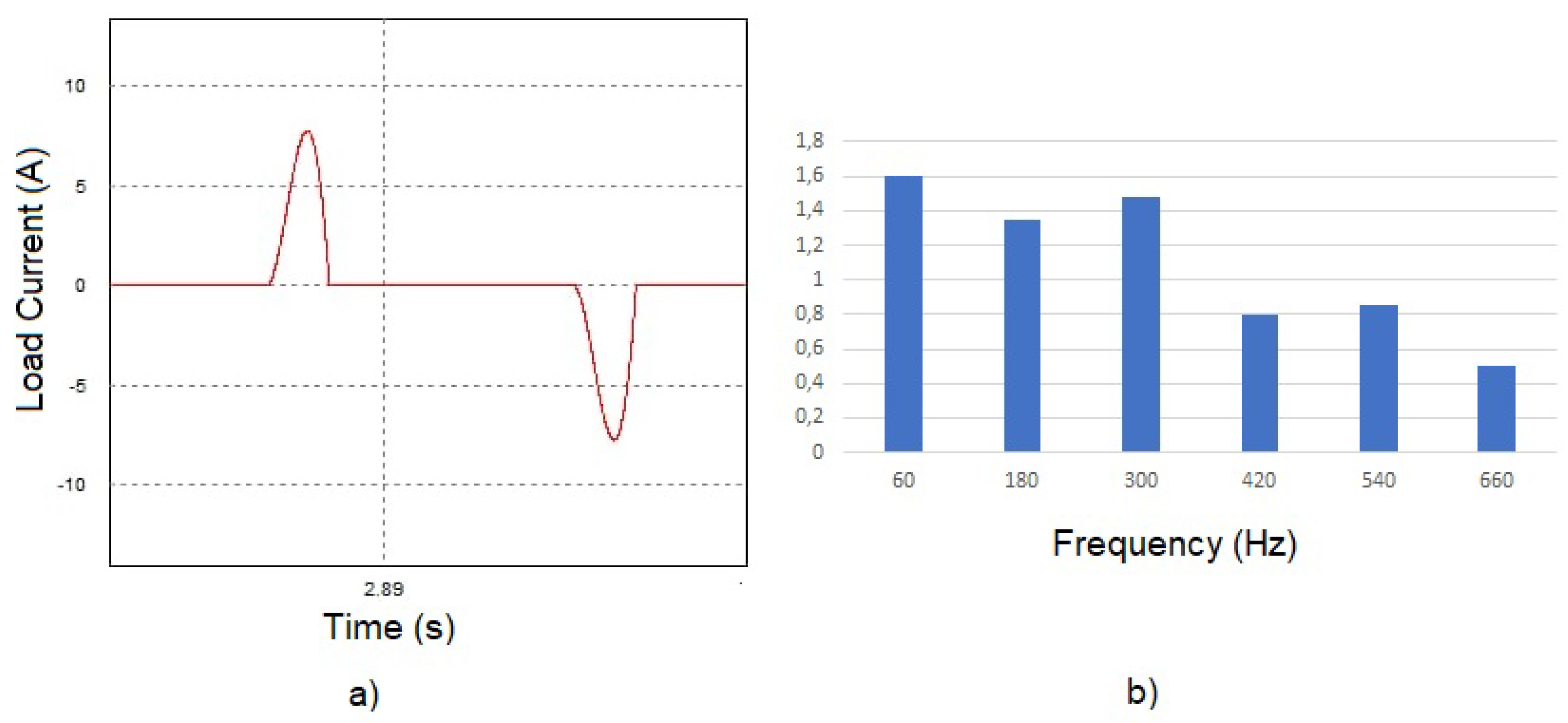
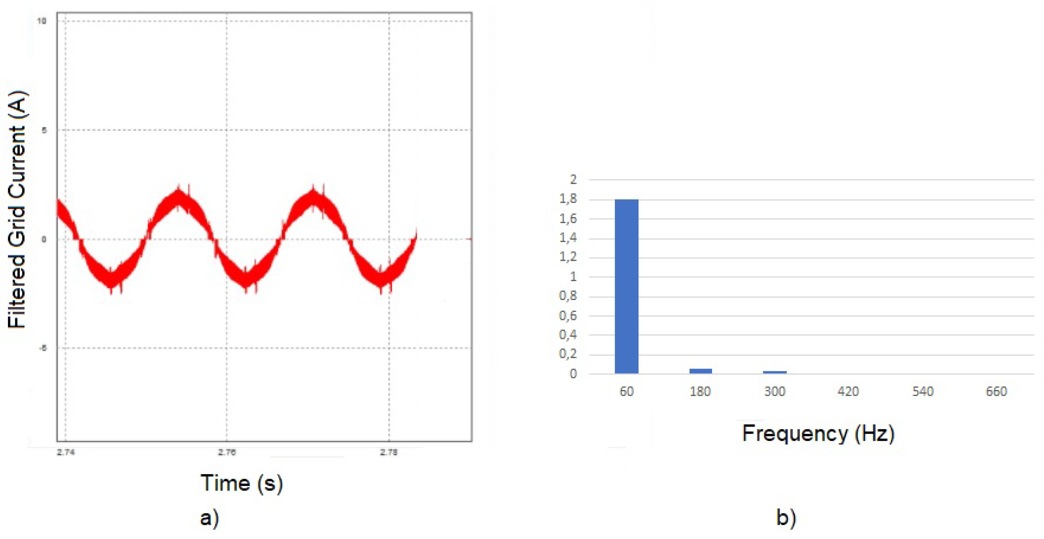
For the implementation of the active power filter, a highly non-linear load was used. The filter in operation should reduce the harmonic current distortions to values lower than 10 per cent. The load is defined by a rectifier with a capacitor and a resistor in parallel on the DC side of the rectifier. The capacitor used was 1 mF with a resistance of 200 ohms. Therefore, the load has an active power of 153.6 W; reactive power of 476 VAr and power factor of 0.302. The grid power supply is 127 Vrms with 60 Hz frequency. The DC bus voltage is 350 V and the switching frequency of IGBTs is 30 kHz. The structure of the APF used is shown in Figure 4. The experimental setup is shown in Figure 5.
Figure 4.
Active power filters (APF) Proposed Topology.
Figure 5.
(a) control setup; (b) instrumentation and measure; (c) semiconductor switches (IGBT) devices.
5. Results
The load current waveform is shown in the Figure 6a. It is noted that its behavior is highly non-linear. The Figure 6b presents the content of the fast Fourier transform (FFT) of this waveform, in which it is possible to notice its high harmonic content. After the APF application, it is possible to observe that the load current was filtered, and all this harmonic content now flows through the filter. Therefore, the grid current presents a sinusoidal shape, as shown in Figure 7a. This sinusoidal behavior is evidenced by the FFT of this signal, presented in Figure 7b.
Figure 6.
(a) Load Current; (b) Load Current FFT.
Figure 7.
(a) Grid Current; (b) Grid Current fast Fourier transform (FFT).
6. Conclusions
Due to the relevance of power electronics devices in production lines and industrial environment, active power filters are powerful tools to improve the power quality. Therefore, in this work, an active power filter was used, that uses a current hall effect sensor to provide the current signals for the control systems.
The application of the technique has stood out for providing precise and high accuracy results, as proven by FFT analysis of the grid and load current. It allowed one to mitigate the harmonic content present in the load. The compensation was correctly achieved, once the total harmonic distortion was lower than 10 per cent, as this work proposed.
In future works, a three-phase system can be assessed. Furthermore, the application of APF in renewable energy systems can be proposed as wind and photo-voltaic.
Conflicts of Interest
The authors declare no conflict of interest.
References
- Falck, J.; Felgemacher, C.; Rojko, A.; Liserre, M.; Zacharias, P. Reliability of Power Electronic Systems: An Industry Perspective. IEEE Ind. Electron. Mag. 2018, 12, 24–35. [Google Scholar] [CrossRef]
- Bose, B.K. Power Electronics, Smart Grid, and Renewable Energy Systems. Proc. IEEE 2017, 105, 2011–2018. [Google Scholar] [CrossRef]
- Mishra, A.K.; Das, S.R.; Ray, P.K.; Mallick, R.K.; Mohanty, A.; Mishra, D.K. PSO-GWO Optimized Fractional Order PID Based Hybrid Shunt Active Power Filter for Power Quality Improvements. IEEE Access 2020, 8, 74497–74512. [Google Scholar] [CrossRef]
- Ferreira, S.C.; Gonzatti, R.B.; Pereira, R.R.; da Silva, C.H.; da Silva, L.E.B.; Lambert-Torres, G. Finite Control Set Model Predictive Control for Dynamic Reactive Power Compensation With Hybrid Active Power Filters. IEEE Trans. Ind. Electron. 2018, 65, 2608–2617. [Google Scholar] [CrossRef]
- Rocha, M.A.; de Souza, W.G.; Serni, P.J.A.; Andreoli, A.L.; Clerice, G.A.M.; da Silva, P.S. Control of three-phase PWM boost rectifiers using proportional-resonant controllers. In Proceedings of the 2018 Simposio Brasileiro de Sistemas Eletricos (SBSE), Niteroi, Brazil, 12–16 May 2018. [Google Scholar] [CrossRef]
- Hou, S.; Fei, J.; Chen, C.; Chu, Y. Finite-Time Adaptive Fuzzy-Neural-Network Control of Active Power Filter. IEEE Trans. Power Electron. 2019, 34, 10298–10313. [Google Scholar] [CrossRef]
- Bosch, S.; Staiger, J.; Steinhart, H. Predictive Current Control for an Active Power Filter With LCL-Filter. IEEE Trans. Ind. Electron. 2018, 65, 4943–4952. [Google Scholar] [CrossRef]
- Pandey, S.K.; Singh, B. Hybrid DSC with Compensation Capability Based Control for Grid Integrated SPV System. In Proceedings of the 2020 IEEE 9th Power India International Conference (PIICON), Sonepat, India, 28 February–1 March 2020. [Google Scholar] [CrossRef]
- Kashif, M.; Hossain, M.; Zhuo, F.; Gautam, S. Design and implementation of a three-level active power filter for harmonic and reactive power compensation. Electr. Power Syst. Res. 2018, 165, 144–156. [Google Scholar] [CrossRef]
- Ramsden, E. Hall-Effect Sensors: Theory and Applications; Elsevier: Amsterdam, The Netherlands; Newnes: Boston, MA, USA, 2006. [Google Scholar]
Publisher’s Note: MDPI stays neutral with regard to jurisdictional claims in published maps and institutional affiliations. |
© 2020 by the authors. Licensee MDPI, Basel, Switzerland. This article is an open access article distributed under the terms and conditions of the Creative Commons Attribution (CC BY) license (https://creativecommons.org/licenses/by/4.0/).