1. Introduction
Screen-printed dry electrodes for electrotherapy applications have been demonstrated in previous work [
1]. However, dispenser printing offers the advantage of lower cost for custom designs compared to screen printing, since no physical screen is required for patterning. It is a direct-write printing technique where the material structures are built via a syringe and nozzle connected to a pneumatic pressure controller [
2]. The printing pattern is automatically controlled by the computer software according to the required design, which makes bespoke designs feasible.
Electrodes are key components of many healthcare devices for diagnostics/monitoring (e.g., ECG, EEG, EMG) and therapeutics (e.g., electrical muscle stimulation for assisted living and rehabilitation). Traditional hydrogel electrodes are not suitable for long-term use because their performance deteriorates over time due to moisture evaporation and contamination build-up resulting from their stickiness. A dry electrode made from Fabink E-0002 paste was used in textile printing in previous work for healthcare applications [
3]. However, the pot-life of Fabink E-0002 is only around 20 min, which is often not sufficient for the fabrication process. The short pot-life of the ink occurs since the viscosity of the paste increases due to crosslinking of the electrode components after mixing. This also creates a challenge during dispenser printing because the syringe pressure needs to be adjusted as the ink’s viscosity increases during printing. This paper introduces and describes the application of a new dry electrode paste called Fabink E-0003. The pot-life of Fabink E-0003 is around three hours.
This work presents the fabrication process and parameters of an electrode array on a textile by dispenser printing. The strategy for interface printing and printing characterization is discussed.
2. Methods and Materials
2.1. Dispenser Printer
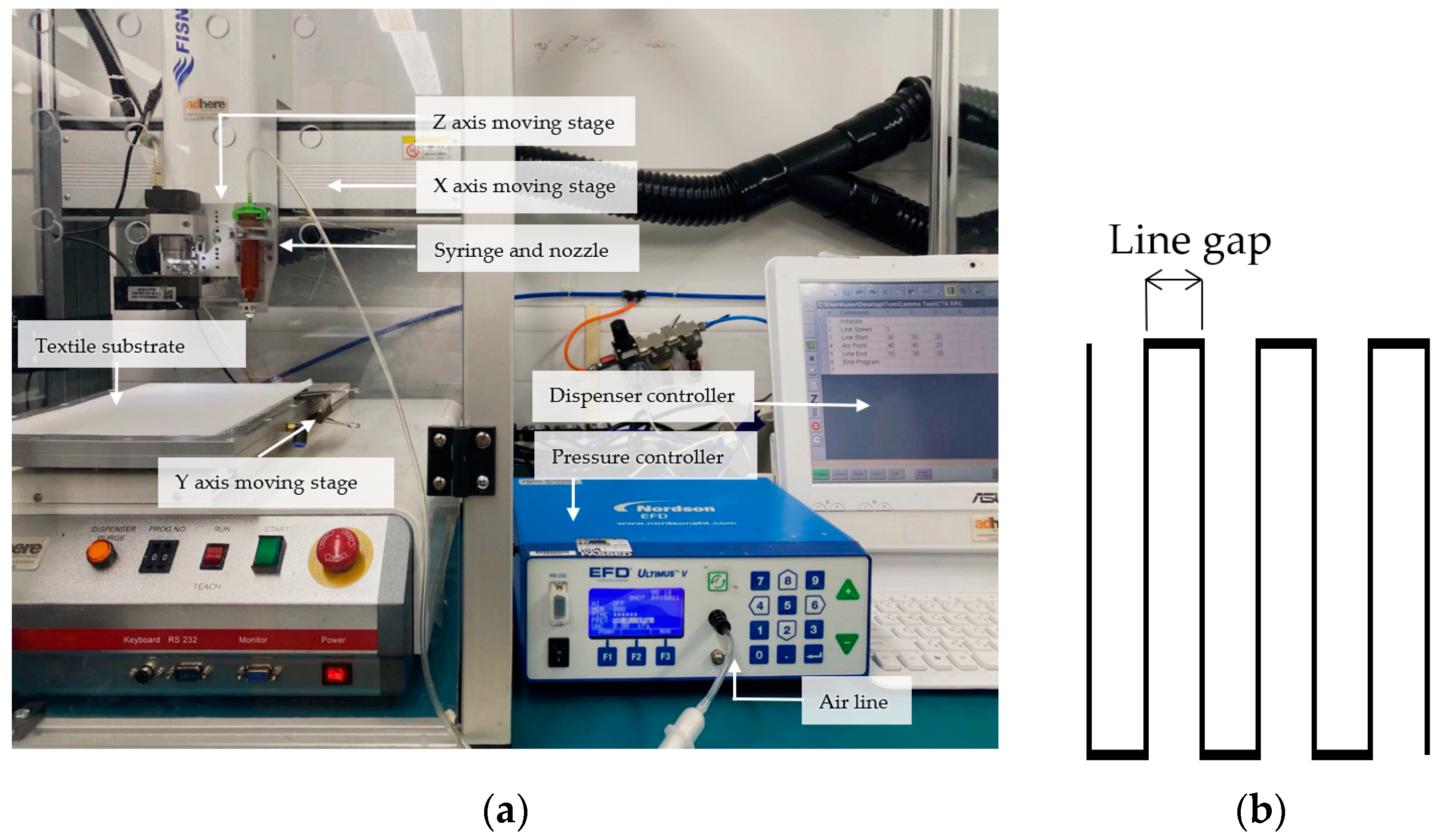
Dispenser printing uses air pressure to dispense inks out of a nozzle onto a substrate. The Fisnar F7300NV 3 Axis dispenser printer used in this study is shown in
Figure 1a. The nozzle can move in the X and Z directions relative to the substrate, and Y direction movement can be achieved by the substrate moving relative to the nozzle. The movement of both the nozzle and the substrate is controlled by a computer system. The movement instructions for the printing of each layer are controlled by the following parameters: printing speed, line gap and nozzle height above the substrate. Line gap is the distance between two parallel lines of a meander printing trace as shown in
Figure 1b. The nozzle can be changed manually to the appropriate size determined by the required print resolution; available nozzle diameters range from 0.15 mm to 1.60 mm. The air pressure is set by the pressure controller depending on the viscosity of the material to be dispensed with a higher viscosity requiring a higher pressure.
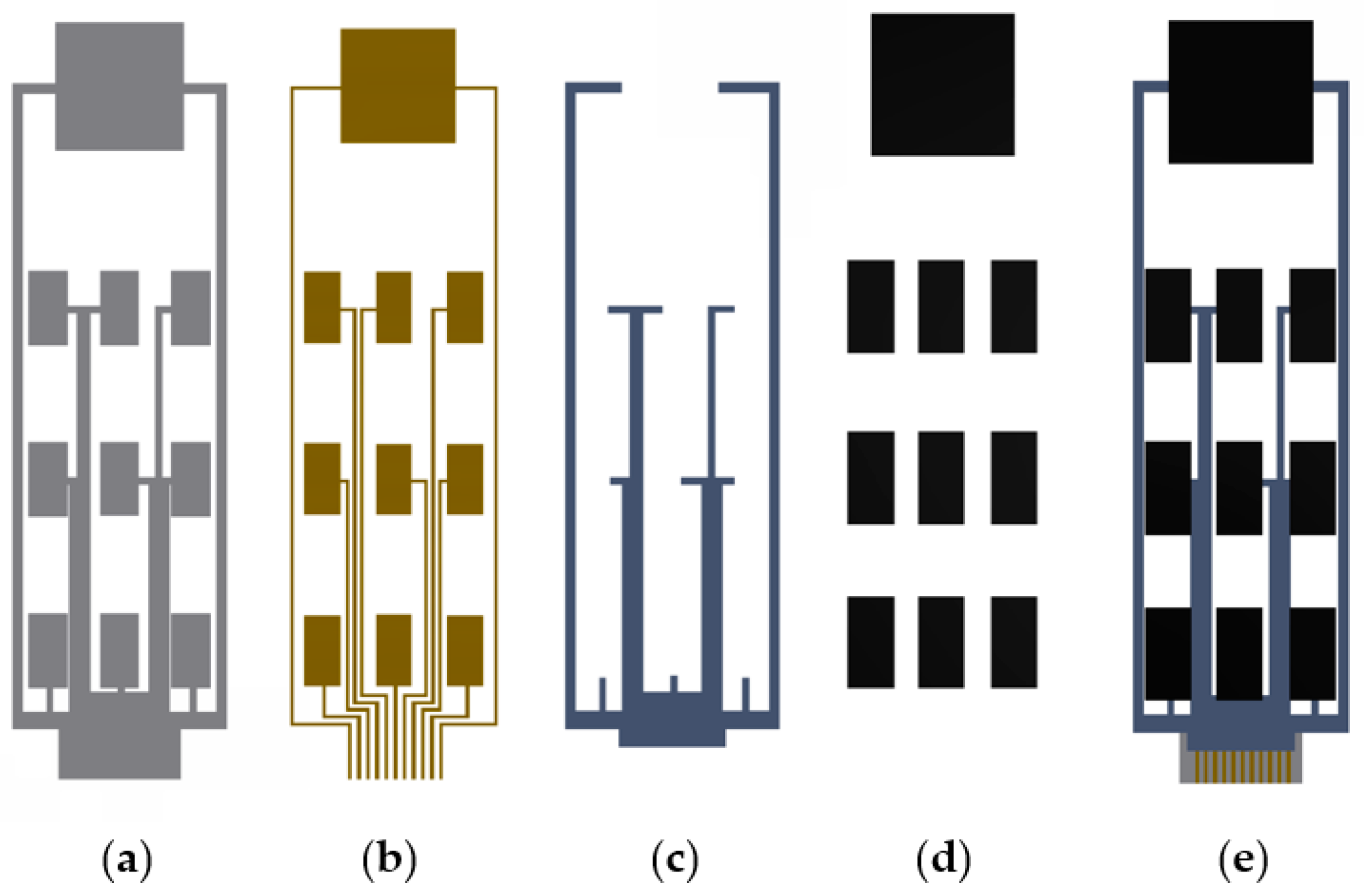
The electrode array for functional electrical stimulation (FES) consists of ten electrode elements comprising nine active electrodes and one common return electrode. As in previous work [
4], the sample consists of four functional layers, as shown in
Figure 2a–d.
Figure 2e shows the final top view of the sample after depositing four layers. The minimum distance between two silver tracks is designed to be 1 mm, which is also the width of the printed conductive tracks.
2.2. Materials
The woven textile substrate is polyester/cotton A1656 white supplied by Whaleys Bradford Ltd. (Bradford, UK). The three functional pastes used in this study are listed in
Table 1. They were supplied by Smart Fabric Inks Ltd. (Southampton, UK). The interface, silver and encapsulation material are the same as those used in previous work [
1]. However, the electrode paste changed to Fabink E-0003.
3. Fabrication Processes
The dispenser printed electrode array consists of four functional layers as shown in
Figure 2. The set-up of the printer for each layer is optimized, and the optimum parameters are listed in
Table 2.
- (1)
Interface
The function of the interface is to fill any gaps in the textile (e.g., between yarns) and create a smooth and flat surface before printing the subsequent layers. As listed in
Table 2, layers 1 and 2 are printed to fill the gaps between textile yarns and create a continuous layer on the textile. Due to the liquid absorption property of the textile, the paste spreads on the bare textile before it is cured. A longer processing time before curing leads to more bleeding. The line gap of the first two prints is set at 1 mm using a nozzle size of 1.6 mm. This saves printing time compared to when a 0.2 mm line gap is used with a smaller nozzle size (0.41 mm) in later layers. Therefore, the paste bleeding is reduced as the printing time is shorter.
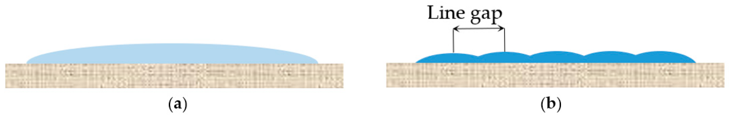
After the first two interface layers are printed, the ink forms an uneven surface on the textile. Layer 3 is printed to smooth the surface by filling in the areas of lower height in the uneven surface. A 0.05 mm height is set between the nozzle and the surface peak. Layers 4 and 5 are printed to achieve the additional filling of the lower height areas, resulting in a flat surface. A line gap of 0.2 mm was used for layers 3 to 5. Dividing one wide printing track into five narrower tracks can create a less-curved surface, as illustrated in
Figure 3.
The interface layer was formed using Fabink IF-UV-1004. UV curing was applied after each print by exposing the sample to a 400 W mercury (Hg) bulb in a UV cabinet supplied by UV Light Technology Ltd. (Birmingham, UK). The UV curing time was 60 s.
- (2)
Silver
The silver layer is printed to form the conductive tracks for interconnections and the conductive pads for the carbon electrodes. The line gap is set as 0.2 mm, which means that a silver track of 1 mm width is achieved by five parallel line prints. Dividing one line into five prints can also reduce the frequency of open circuits leading to improved sample yield and quality. The conductive layer was formed using Fabink TC-C4007. The paste was cured in a box oven at 100 °C for 30 min.
- (3)
Encapsulation
The encapsulation layer is printed to protect the conductive tracks and provide electrical insulation. The encapsulation layer was formed using Fabink IF-UV-1004 and cured as for the interface.
- (4)
Carbon electrode array
Carbon electrodes, which form the contact layer to the skin, are printed on top of the conductive pads. The electrode paste was cured in a box oven at 120 °C for 30 min resulting in an electrode layer with a thickness of 1.3 mm.
4. Results and Discussion
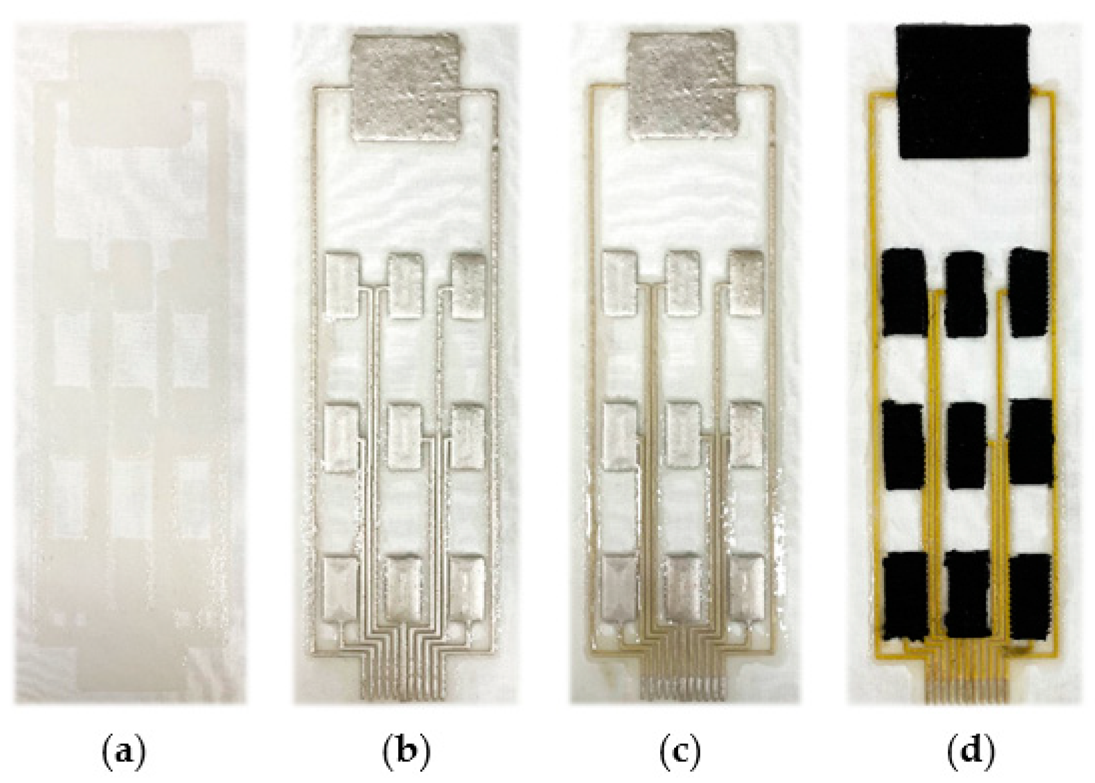
The samples after printing each of the functional layers are shown in
Figure 4.
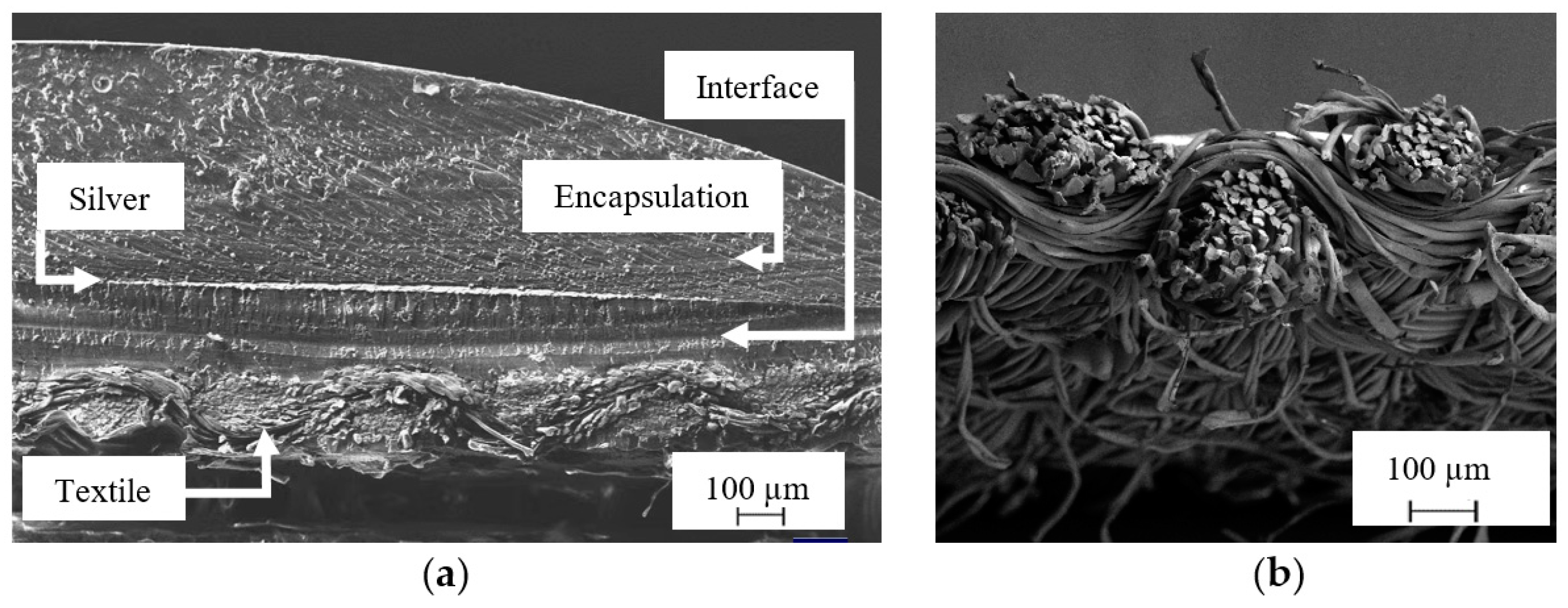
Figure 5a is an SEM image showing the cross-section of the conductive layer printed on the textile.
Compared with the bare uncoated textile, which is shown in
Figure 5b, the surface roughness is decreased by the interface layer. The curved surface caused by surface tension can be observed in the surface of the encapsulation layer in
Figure 5a. In contrast, the interface layer and silver layer are flat with a less-curved surface.
5. Conclusions
This paper has achieved an all dispenser printed electrode array structure on textile. Dispenser printing is a direct write process, which allows the design of the array to be adjusted to achieve bespoke one-off designs tailored to suit an individual’s needs. The minimum gap between conductive tracks of 1 mm required in the design was achieved. The process details and materials used are presented. The array consists of ten electrode elements for functional electrical stimulation (FES), including nine active electrodes and one common return electrode. Future work will test the electrode array for muscle stimulation.
Author Contributions
Conceptualization, N.G., J.T. and K.Y.; methodology, Z.A., J.T. and K.Y.; software, Z.A. and M.L.; validation, M.L.; writing—original draft preparation, M.L.; writing review and editing, J.T. and K.Y.; visualization, M.L.; supervision, S.B. and K.Y.; project administration, J.T. and K.Y.; funding acquisition, J.T. and K.Y. All authors have read and agreed to the published version of the manuscript.
Funding
This research was funded by EPSRC under grant number EP/S001654/1.
Institutional Review Board Statement
Not applicable.
Informed Consent Statement
Not applicable.
Data Availability Statement
Conflicts of Interest
S.B., J.T. and K.Y are Directors of Smart Fabric Inks Limited.
References
- Liu, M.; Glanc-Gostkiewicz, M.; Beeby, S.; Yang, K. Fully Printed Wearable Electrode Textile for Electrotherapy Application. Proceedings 2021, 68, 12. [Google Scholar] [CrossRef]
- Greig, T.; Torah, R.; Yang, K. Investigation of Nozzle Height Control to Improve Dispenser Printing of E-Textiles. Proceedings 2021, 68, 6. [Google Scholar] [CrossRef]
- Liu, M.; Ward, T.; Young, D.; Matos, H.; Wei, Y.; Adams, J.; Yang, K. Electronic textiles based wearable electrotherapy for pain relief. Sens. Actuators A Phys. 2020, 303, 111701. [Google Scholar] [CrossRef]
- Yang, K.; Meadmore, K.; Freeman, C.; Grabham, N.; Hughes, A.; Wei, Y.; Torah, R.; Glanc-Gostkiewicz, M.; Beeby, S.; Tudor, J. Development of user-friendly wearable electronic textiles for healthcare applications. Sensors 2018, 18, 2410. [Google Scholar] [CrossRef] [PubMed] [Green Version]
| Publisher’s Note: MDPI stays neutral with regard to jurisdictional claims in published maps and institutional affiliations. |
© 2022 by the authors. Licensee MDPI, Basel, Switzerland. This article is an open access article distributed under the terms and conditions of the Creative Commons Attribution (CC BY) license (https://creativecommons.org/licenses/by/4.0/).


