Abstract
We developed an active vibration isolation system with a high-rigidity support design to reduce sensitivity to platform motion disturbances. By integrating absolute acceleration and velocity feedback control, the system eliminates structural resonance and lowers the natural frequency. The concept was validated through theoretical analysis, numerical simulations, and experiments. Results show that feedback control not only eliminates resonance amplification but also reduces the natural frequency by 55%. These findings confirm that the proposed system enhances resistance to platform disturbances while maintaining effective floor vibration isolation.
1. Introduction
The development of vibration isolation technology is extremely important for micro-nano process equipment with continuously shrinking process precision. By isolating environmental vibrations, advanced sensitive equipment can be ensured to be safe during processing and testing. Its application areas include wafer inspection equipment in the semiconductor industry [1], microscopes used in biomedicine and materials science [2], and gravity wave detectors that are being vigorously developed in the field of astronomy [3]. All of them rely on vibration isolation technology to promote the development of the high-tech industry chain.
The vibration interference source can be divided into the following two types according to the transmission path. The first is the indirect interference of floor vibration interference transmitted to sensitive equipment through the vibration isolation system, such as people walking or ground movement. If the interference source directly acts on the vibration isolation system, it is called direct interference, such as motor acceleration and deceleration movement or airflow interference. To suppress indirect interference, traditional passive isolators achieve effective floor vibration isolation by employing low-stiffness designs with natural frequencies around 4–5 Hz.
However, such designs inevitably increase sensitivity to direct disturbances. Conversely, high stiffness supports improve resistance to direct interference but compromise floor isolation. This inherent trade-off has limited the application of vibration isolation technology in advanced process equipment; on the contrary, although high-rigidity support can obtain extremely superior direct interference suppression performance, it also sacrifices the ability to suppress floor vibration. However, with the continuous development of technology, advanced process equipment manufacturers have put forward mutually restraining vibration isolation requirements, that is, to reduce the sensitivity of the equipment to its floor disturbance, the structural support rigidity must be low enough, but at the same time, the system rigidity must be high enough to resist the interference force directly acting on the platform during high-speed testing of the equipment.
There have been studies based on negative stiffness passive vibration isolation systems [4]. Without affecting the static support stiffness of the spring, negative stiffness springs can be used to offset the support stiffness, thereby reducing the dynamic stiffness of the vibration isolation system and achieving the characteristics of high static stiffness and low natural frequency. However, the system presents low-frequency resonance and long transient response time, which have restricted the application of traditional passive vibration isolation systems in sensitive equipment. Therefore, the active vibration isolation system is used in the passive vibration isolation structure with a sensing brake module so that the brake element outputs a reverse vibration wave to offset the platform movement, thereby achieving the purpose of suppressing vibration.
For example, Hong et al. [5] studied the concept of Skyhook damping and used absolute velocity feedback control to eliminate the resonance amplification effect of the passive vibration isolator. They improved the transient response and robustness of the system and lowered the atomic force microscopy (AFM) resolution to 3 nm. Integral force feedback control is also used to suppress resonance amplification and achieve excellent vibration isolation performance [6]. However, to obtain the best vibration isolation performance, the structural design of the above-mentioned system mostly adopts a low rigidity design, also known as a soft installation system. This decreases the ability to resist direct disturbances, so it can only be applied to detection equipment that is almost stationary during the detection process, such as electron microscopes. In absolute acceleration feedback control technology, the concept of virtual mass is used [7]. The natural frequency of the isolator is reduced, and the vibration isolation performance of the medium and high frequencies can be improved, but the vibration level of the resonant frequency will be amplified. Therefore, if the above-mentioned virtual mass and skyhook damping control concepts are integrated, the natural frequency of the system can be reduced while eliminating structural resonance, thereby improving the performance of suppressing floor and platform motion interference.
Although extensive literature has proposed vibration isolation strategies based on low-rigidity systems combined with active control for highly sensitive equipment, these approaches primarily demonstrate excellent isolation performance against floor-induced disturbances (i.e., indirect interference). However, there remains a notable gap in systems capable of simultaneously mitigating both direct and indirect interference, as these two objectives are conceptually constrained by opposing design requirements. To address this limitation, a novel vibration isolation strategy has been developed, based on the principles of skyhook damping and virtual mass control as proposed by numerous scholars. This approach employs high-rigidity passive support to enhance resistance against direct disturbances, while absolute acceleration control is utilized to lower the system’s natural frequency, thereby improving its capacity to suppress indirect interference. Furthermore, the integration of absolute velocity feedback control effectively attenuates resonance amplification, enhances low-frequency isolation performance, and contributes to overall system stability.
2. Active Vibration Isolation System
We examined the configuration structure of the proposed active vibration isolation system to understand the transfer function expression of the basic components. Then, a control model was proposed with its mathematical model and vibration isolation performance evaluation index.
2.1. Description of Vibration Isolation System
The configuration of the active vibration isolation system examined in this study is illustrated in Figure 1a, with a corresponding schematic representation provided in Figure 1b. The system employs passive spring elements to support the load and attenuate high-frequency floor vibrations. An equivalent mass of 38 kg is positioned on the platform to simulate the weight of sensitive equipment. To implement active vibration isolation, a high-sensitivity, low-frequency accelerometer (WR731A) is mounted on the platform to serve as a feedback control signal; an identical sensor is also placed on the floor to assess ambient vibration levels. A voice coil brake (VCM), developed in-house, is installed at the center of the platform to generate counteracting vibration forces based on the principle of destructive interference, thereby suppressing platform motion. The feedback signal is first amplified using an analog circuit with a gain factor of 52, followed by bandpass filtering to eliminate noise outside the controllable frequency bandwidth. The intended bandpass range was as follows: f1 = 0.3 Hz (1 order) to f2 = 50 Hz (2 orders). The transfer function Ga (s) of this analog amplification and filtering circuit can be expressed in Equation (1).
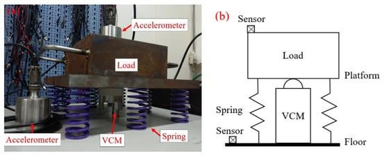
Figure 1.
(a) Active vibration isolation system configuration; (b) System schematic.
In addition, the dynamic range of the VCM and driving circuit used is much larger than the control bandwidth, so if it is expressed as a constant, the driving module function GVCM = 0.45 (N/V).
2.2. Model Construction
The vibration isolation strategy proposed in this study uses rigid springs to eliminate high-frequency vibrations and intends to use active control technology to attenuate low- and medium-frequency interference. This feature uses high-rigidity support springs to make the natural frequency of the overall vibration isolation system >10 Hz, improve the resistance of the vibration isolation system to direct disturbances, and achieve excellent vibration isolation performance at low and medium frequencies through active control, thereby overcoming the contradictory vibration isolation requirements proposed by advanced equipment. The main goals of the proposed control strategy are to add skyhook damping to improve the system’s robustness and stability and eliminate the resonance amplification effect, and add virtual mass to reduce the system’s natural frequency and enhance the medium and high frequency vibration isolation performance. The control technology concept described in the former is shown in Figure 2. The braking force generated by the control system can be equivalent to the effect of the damping csky hanging in the air. Because csky is not affected by the interference of the floor, the increase in damping csky suppresses resonance and the high-frequency vibration isolation performance. In addition, the braking force can be used to give the system a virtual mass, thereby increasing the system’s equivalent mass and reducing the natural frequency.
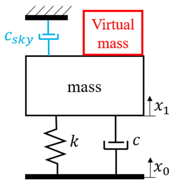
Figure 2.
Concept diagram of control combining skyhook damping and virtual mass.
The proposed complete active control model is shown in Figure 3, which includes passive components such as sensing and braking modules, amplification and filtering circuits, and controllers.
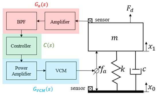
Figure 3.
Complete architecture of the active control system.
The motion equation of this system is as follows.
Here, m, c, and k represent the load mass, viscous damping, and support rigidity, respectively, x0 and x1 represent the floor displacement and platform displacement, and Fd and fa represent the direct interference force and braking force.
The braking force fa follows the control concept of virtual mass and skyhook damping, generates its virtual mass with absolute acceleration feedback, and combines the load mass m and the virtual mass into equivalent mass to achieve the purpose of reducing the natural frequency of the system and improving the vibration isolation performance of medium and high frequencies. The skyhook damping uses absolute velocity feedback control, adds its damping csky, and combines the system’s viscous damping to make the vibration isolation system damping ratio greater than 1, thereby eliminating resonance amplification. Combining the above control strategies, if direct interference (Fd = 0) is not considered first, then only the braking force fa that suppresses the floor vibration interference x0 can be expanded to the following Equation (3).
Here, and represent the control gains of absolute acceleration and velocity, which can be adjusted inside the controller C(s). The internal relationship of is expressed as follows.
Here, and are the transfer function of the analog filter amplifier circuit and the driving constant of the brake module, and represents the sensitivity of the sensor. Therefore, the feedback control equivalent transfer function of this system, or also known as the transmissibility function (Tr.), can be expressed as:
The control technology can adjust the system damping and mass characteristics by controlling the gain (, ). To consider the sensitivity of the vibration isolation system to direct interference, according to the motion equation of Equation (2), assuming that the floor vibration (i.e., ignoring indirect interference), and considering the vertical axial direct interference and the braking force imposed on the load mass, the compliance function (Co) of the system is expressed as follows.
Equation (5) expresses the isolation capability of the vibration isolation system for floor vibration, while Equation (6) presents the system’s resistance to direct interference by unit force . In addition, if the response characteristics of the bandpass filter contained in are considered to have maximum flatness within the bandwidth, and the low-frequency phase lag can be ignored, the frequency response characteristics of this filter can be ignored within the limited bandwidth to simplify the analysis. By considering that the damping of general metal structure systems is extremely small, is set. Combining the above conditions, Equations (5) and (6) can be simplified to the following.
Here, , and Equation (7) is expressed as a typical second-order system of spring, damping, and mass, then the undamped natural angular frequency of the system is:
The effective attenuation frequency of the vibration isolation system must be higher than times the natural frequency. That is, as shown in Equation (9), when the feedback gain continues to increase, moves to a low frequency, which means that the control strategy can effectively improve the vibration isolation bandwidth and vibration attenuation. If is substituted into Equations (7) and (8) and the absolute value is taken, the relationship between the transmissibility and compliance function frequency response magnitude at the natural frequency is obtained.
If is constant, then when , the transmission rate at the natural frequency drops below 1, the resonance is perfectly eliminated. According to Equation (11), as the support rigidity and feedback gain increase, the compliance of the natural frequency will decrease accordingly, which effectively improves the resistance to direct interference, and illustrates the effectiveness of the high rigidity design proposed in this article in suppressing direct interference.
3. Control System Analysis and Simulation
The numerical analysis software MATLAB 2016 version was used to evaluate the various vibration isolation performance indicators of the proposed control architecture.
3.1. Control Strategy Practice Method
For the proposed control method, an accelerometer was used to measure the absolute acceleration vibration signal and feed it back to the controller . To obtain the required acceleration and velocity physical quantities, the controller is designed as a proportional and integral controller. The expression is as follows.
Considering the practical control application, the DC signal component mixed in the analog circuit causes low-frequency signal drift and output saturation nonlinearity after integration. This deteriorates the low-frequency vibration isolation. Therefore, the moving average filter (MAF) based on digital signal processing is introduced, and the filter function is expressed as follows.
where is the number of samples and is the input vibration signal. The overall control architecture is shown in Figure 4. The input DC signal is estimated by MAF, and the estimated value is multiplied by a unit negative gain and superimposed with the original signal to eliminate the DC level of the original signal.
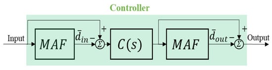
Figure 4.
Overall controller internal architecture.
After this signal is calculated by the control algorithm , the output is also estimated by MAF, and the output DC signal is filtered to prevent signal integral drift. However, in real-time control, to obtain an accurate estimated value, must meet Equation (14).
Here, is the number of samples per second of the controller, and is the drift frequency (Hz) of the signal to be filtered. However, if the signal to be filtered is lower in frequency, the amount of data increases. The heavy amount of data calculation easily enables control phase delay and reduces its stability. Therefore, a more efficient algorithm strategy reduces the amount of calculation through the feedback algorithm, which is rewritten to Equation (13).
The instantaneous calculated at the previous moment is added to the newly input signal , and the oldest data point is subtracted to estimate the current . The iteration process is observed without complicated calculations, which greatly reduces the expensive calculation time. In addition, the filtering strategy is more robust to DC drift caused by time-varying environments (such as temperature changes). The controller continuously estimates the instantaneous drift within each unit sampling time and then compensates and filters the drift, which ensures the stability and robustness of the control process.
3.2. Numerical Simulation
The proposed control methodology is outlined, including potential implementation challenges and corresponding improvement strategies. The high-rigidity active vibration isolation structure and the conventional low-rigidity passive vibration isolation system are subjected to numerical simulation and analysis. The essential parameters for system simulation are presented in Table 1. For the characterization of the amplified filter transfer function , Equation (1) is used.

Table 1.
Numerical simulation parameters.
The given physical parameters are substituted into the transmissibility (Tr) and compliance (Co) functions defined in Equations (5) and (6). To incorporate virtual mass and skyhook damping, the feedback gains are set to ka = 15 and kv = 700. Conversely, setting the feedback gains to zero allows evaluation of the system’s passive vibration isolation performance. As illustrated in Figure 5 and Figure 6, the natural frequency of the low-stiffness support (k = 37 kN/m) is 5 Hz, which is substantially lower than the 11 Hz natural frequency of the high-stiffness support (k = 181 kN/m). While the lower stiffness yields superior isolation against floor vibrations, it compromises structural rigidity. The proposed high-rigidity support structure, when combined with the active control strategy, effectively eliminates resonance and utilizes virtual mass to attenuate vibration interference across the control bandwidth. Its isolation performance surpasses that of the low-rigidity system. Compliance analysis shown in Figure 6 indicates that the passive high-rigidity support system provides substantial resistance to static loads and low-frequency direct disturbances. Upon activation of the control system, vibration isolation is significantly enhanced across the sensitive frequency range of 1–100 Hz [8], which is critical for advanced process equipment. These findings confirm that the proposed control architecture substantially improves the suppression of both direct and indirect vibration interference affecting sensitive equipment.
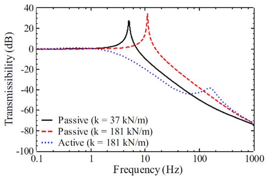
Figure 5.
Transmissibility analysis results.
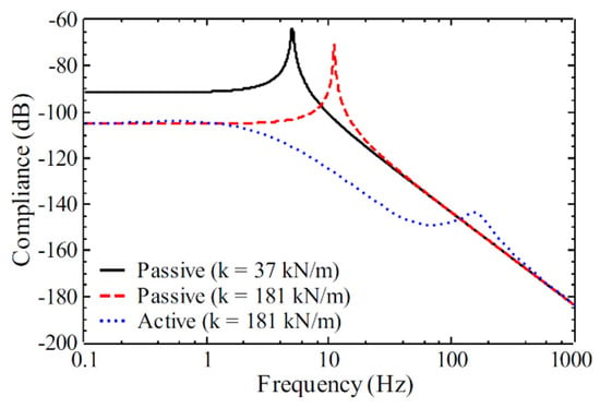
Figure 6.
Compliance analysis results.
4. Result
Vibration isolation and attenuation performance were analyzed to evaluate compliance with the requirements of sensitive equipment, as defined by the common vibration code (VC) for Sensitive Equipment [8].
4.1. Experiment
By adjusting the number of passive support springs, high-stiffness and low-stiffness passive vibration isolation systems are obtained (Figure 1a). The stiffness changes in the two systems differ by about 5 times. This verifies the vibration isolation performance under different stiffness and evaluates the feasibility of the high-stiffness support combined with the active vibration isolation technology proposed. In addition to using transmissibility as the primary evaluation metric, the specifications outlined in the general vibration standard for sensitive equipment are employed to assess whether the system’s isolation performance satisfies the vibration criterion level (VC-E) criteria required for nanoscale instrumentation. To conduct this evaluation, low-frequency accelerometers (WR731A) are positioned on both the floor and the platform, and their signals are analyzed using a spectrum analyzer (B&K 3560C) for frequency response function and 1/3 octave band analysis. The feedback control system is implemented using the National Instruments PXI chassis (PXI-1042Q), equipped with analog-to-digital (ADC, PXI-6229) and digital-to-analog (DAC, PXI-6733) acquisition cards for signal processing and output.
4.2. Results
As illustrated in the transmissibility curve in Figure 7, the natural frequencies of the high-rigidity and low-rigidity passive vibration isolation systems are 11 and 5 Hz, respectively. The low-rigidity support demonstrates superior attenuation performance, as confirmed by numerical analysis; however, this improvement comes at the expense of reduced suppression of direct disturbances, rendering it less desirable for sensitive applications. Although passive isolators moderately attenuate high-frequency vibration interference, low-frequency resonance remains a critical concern due to its potential to adversely affect sensitive equipment.
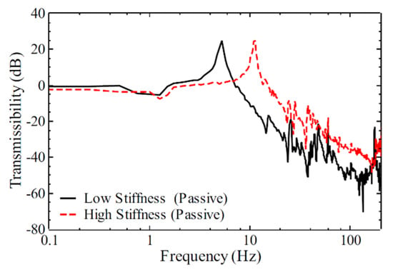
Figure 7.
Transmissibility curve of passive vibration isolator.
Figure 8 presents the high-rigidity support structure integrated with virtual mass and skyhook damping control. Experimental results indicate that the introduction of virtual mass reduces the natural frequency from 11 to 5 Hz—a reduction of approximately 55%—while simultaneously enhancing attenuation across mid- and high-frequency ranges. Nevertheless, low-frequency resonance persists. This limitation is effectively addressed through the implementation of damping control. The proposed vibration isolation strategy mitigates direct interference via high-rigidity support and resonance amplification through active control, significantly reducing wide-band vibration amplitudes. At the original resonance frequency of the passive isolator (11 Hz), vibration attenuation exceeds −40 dB (a 100-fold reduction), and attenuation across the remaining controllable frequency band ranges from −10 to −20 dB.
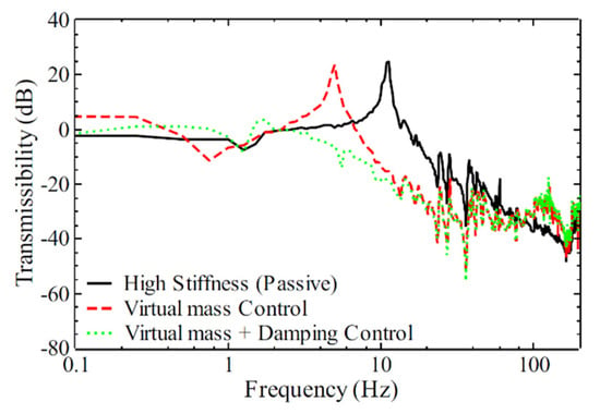
Figure 8.
Transmissibility curve of high rigidity support combined with active control.
DC signal drift influences system stability and low-frequency performance. Although a slight reduction in isolation performance below 2 Hz is observed in the transmissibility curve of Figure 8, the degradation is minimal. This outcome validates the effectiveness of MAF estimation and the DC signal suppression strategy in minimizing low-frequency drift and enhancing system stability. Figure 9 further demonstrates that the high-rigidity support structure, combined with virtual mass and skyhook damping control, can reduce floor vibration levels from vibration criterion A (VC-A) (typical of general technology facilities) to VC-E, as required by vibration standards for nanoscale instruments and exposure equipment.
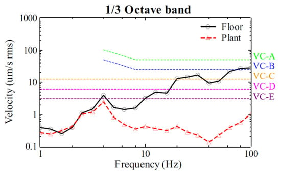
Figure 9.
Active vibration isolation control for sensitive equipment vibration standard assessment.
5. Conclusions
The vibration isolation system proposed in this study achieves a fivefold increase in rigidity compared to conventional low-rigidity installations, thereby enhancing the suppression of direct interference. Simultaneously, the integration of velocity and acceleration feedback control enables effective attenuation of indirect interference within the sensitive frequency range of 1–100 Hz, relevant to advanced process equipment. This dual capability allows the system to maintain high performance in both direct and indirect vibration isolation without compromising design integrity. Furthermore, the controller incorporates MAF to estimate and eliminate the DC component of the vibration signal, thereby limiting low-frequency gain and suppressing integral drift. This contributes to improved system stability and robustness.
Experimental results confirm that, upon activation of active control, vibration attenuation at the original resonance frequency reaches −40 dB, with additional attenuation of −10 to −20 dB across other control bands. In accordance with general standards for sensitive equipment, the system successfully reduces vibration levels from VC-A to VC-E, suitable for nano-resolution instruments. MAF also maximizes suppression of low-frequency degradation, maintaining control system stability. In addressing the conflicting requirements of advanced process equipment—namely, the need for both low natural frequency and high structural rigidity—the proposed high-rigidity support and feedback control strategy overcomes the limitations of traditional vibration isolators. Active vibration isolation systems with even greater rigidity and lower natural frequencies are required to enhance isolation performance for both floor and platform disturbances to meet the stringent demands of next-generation technological applications.
Author Contributions
Conceptualization, methodology and mathematical model, and writing—original draft preparation, Y.-H.L.; validation and analysis, P.-Y.H. All authors have read and agreed to the published version of the manuscript.
Funding
This research was funded by National Science and Technology Council (NSTC) of Taiwan under contract numbers: MOST 108-2221-E-218-027 and NSTC 113-2221-E218-022.
Institutional Review Board Statement
Not applicable.
Informed Consent Statement
Not applicable.
Data Availability Statement
Data will be available on request.
Conflicts of Interest
The authors declare no conflicts of interest.
References
- Heertjes, M.; de Graaff, K.; van der Toorn, J.-G. Active Vibration Isolation of Metrology Frames; A Modal Decoupled Control Design. J. Vib. Acoust. 2005, 127, 223–233. [Google Scholar] [CrossRef]
- Eaton, P.; West, P. Atomic Force Microscopy; Oxford University Press: Oxford, UK, 2010. [Google Scholar]
- Matichard, F.; Lantz, B.; Mason, K.; Mittleman, R.; Abbott, B.; Abbott, S.; Allwine, E.; Barnum, S.; Birch, J.; Biscans, S.; et al. Advanced LIGO two-stage twelve-axis vibration isolation and positioning platform. Part 2: Experimental investigation and tests results. Precis. Eng. 2015, 40, 287–297. [Google Scholar] [CrossRef]
- Le, T.D.; Ahn, K.K. A vibration isolation system in low frequency excitation region using negative stiffness structure for vehicle seat. J. Sound Vib. 2011, 330, 6311–6335. [Google Scholar] [CrossRef]
- Hong, J.; Park, K. Design and control of six degree-of-freedom active vibration isolation table. Rev. Sci. Instrum. 2010, 81, 035106. [Google Scholar] [CrossRef] [PubMed]
- Teo, Y.R.; Fleming, A.J. Optimal integral force feedback for active vibration control. J. Sound Vib. 2015, 356, 20–33. [Google Scholar] [CrossRef]
- Ning, D.-Y.; Sun, C.-L. Study on active vibration isolation based on electromagnetic responses. In Proceedings of the 2012 IEEE International Conference on Computer Science and Automation Engineering (CSAE), Zhangjiajie, China, 25–27 May 2012; pp. 648–652. [Google Scholar]
- Amick, H.; Gendreau, M.; Gordon, C. Evolving criteria for research facilities: I—Vibration. In Proceedings of the SPIE Conference 5933: Buildings for Nanoscale Research and Beyond, San Diego, CA, USA, 31 July–1 August 2005; p. 13. [Google Scholar]
Disclaimer/Publisher’s Note: The statements, opinions and data contained in all publications are solely those of the individual author(s) and contributor(s) and not of MDPI and/or the editor(s). MDPI and/or the editor(s) disclaim responsibility for any injury to people or property resulting from any ideas, methods, instructions or products referred to in the content. |
© 2025 by the authors. Licensee MDPI, Basel, Switzerland. This article is an open access article distributed under the terms and conditions of the Creative Commons Attribution (CC BY) license (https://creativecommons.org/licenses/by/4.0/).