Abstract
Thermal energy storage (TES) system is a technique that stores thermal energy in a storage medium for later use to balance demand and supply in industrial operations. In this study, a sensible thermal energy storage tank composed of concrete block and heat transfer fluid (HTF) passages is proposed. Slag and concrete particles are introduced to analyze the performance of the TES system. A comprehensive numerical model is developed using an energy balance approach combined with an enthalpy-based methodology. The temperature distribution is presented at different time intervals during the charging and discharging cycle of TESS. In comparison with a slag-filled TES tank, the concrete-filled TES tank charged and discharged quickly. The findings reveal that a TES tank filled with concrete is more efficient than a TES tank filled with slag.
1. Introduction
Due to the daily scarcity of nonrenewable energy reserves, renewable energy options must be investigated for energy needs. Today, energy needs have become cost intensive owing to limited supply due to higher costs, environmental pollution, and health issues. Renewable energy-based smart energy systems are gaining popularity. The temporal mismatch between energy supply and demand is also a difficult issue to deal with, which can be bridged by designing a thermal energy storage system for adding or removing heat from a storage medium at different time intervals [1].
For stabilizing the discharging outflow air temperature, a thermal energy storage tank containing sensible and latent thermal energy is designed, tested, and simulated at 575 °C and above [2]. The use of solid bricks as a storage material in a thermal energy storage system (TES) is intended to improve the performance of sensible storage systems, and the results indicated that the ability to store data is excellent under this system [3]. During the charging cycle, heat transfer fluid is transported to a thermal energy storage system through solar fields. The cold fluid absorbs heat from the thermal energy storage system to complete the discharging cycle. Due to its low cost, stability, and other thermal characteristics, concrete is employed as a storage medium [4]. The impact of different concrete structures on the performance of thermal energy storage devices is investigated. Through the thinnest thermocline region of a concrete thermal energy storage tank, rod bundle construction has the greatest discharge efficiency and the longest discharge duration [5].
Industrial efficiency can be improved by utilizing the maximum amount of energy from industrial waste heat recovery operations to offset variations Thermal energy storage devices must be developed to take advantage of the full potential of solar thermal energy [6]. Furthermore, in order to satisfy the demands of nature, it is necessary to create more affordable storage solutions, as solar thermal energy is not available at all times at specific locations.
2. TES Design
2.1. Geometrical Model
A thermal energy storage tank with a diameter of 5 m and 46 channels for heat transfer fluid (HTF) to travel through is built. Each channel included 250 slag particles that were used to store energy to be used later. Concrete material is put outside the HTF route, while slage particles are deposited within the HTF channel. As stated in Table 1, the tank has a length of 7.5 m and a porosity (ε) of 0.3.

Table 1.
Thermal energy storage tank dimensions.
2.2. Materials
The materials utilized were 95 wt.% laboratory-grade concrete and 99 wt.% laboratory-grade slag. The characteristics of concrete particles were the same as in [5], whereas the values for slag particles were taken from [7]. Thermal capacity, as a function of temperature (specific heat capacity × density), was computed for both particles, whereas thermal conductivity was calculated by multiplying density, specific heat capacity, and thermal diffusivity. Table 2 lists the thermal characteristics of both heat storage material samples found in the literature.
Table 2.
Thermal properties of heat storage materials as a function of temperature.
3. Energy Model Description and Simulation
3.1. Energy Model Description
An energy balance technique combined with an enthalpy method, controlled by distinct equations for a sensible heat storage system, was used to evaluate the developed transient numerical model. The system was designed to save the maximum amount of energy possible while charging so that it can be used during discharging. A storage tank model with a diameter of 5 m and a height of 7.5 m was created for this purpose, with a total of 45 channels containing 250 particles in each channel and a porosity of 0.3 m.
3.2. Initial and Boundary Conditions
Initial conditions are needed to initialize the solutions, while boundary conditions are required for running the simulation continuously and are considered mandatory to meet the convergence requirements. The numerical model’s formulated equations were solved using an appropriate set of starting and boundary conditions [6]. At t = 0 for charging, while = 858.15 for discharging was used. At inlet section for t > 0, velocity is 0.005 m/s and Thtf is 838.15 K. The boundary conditions at symmetry axis are: , at the outer wall are , while at the outlet of the storage tank are .
The thermal charging capacity of the tank was calculated by
The thermal discharging capacity of the tank is
4. Results and Discussion
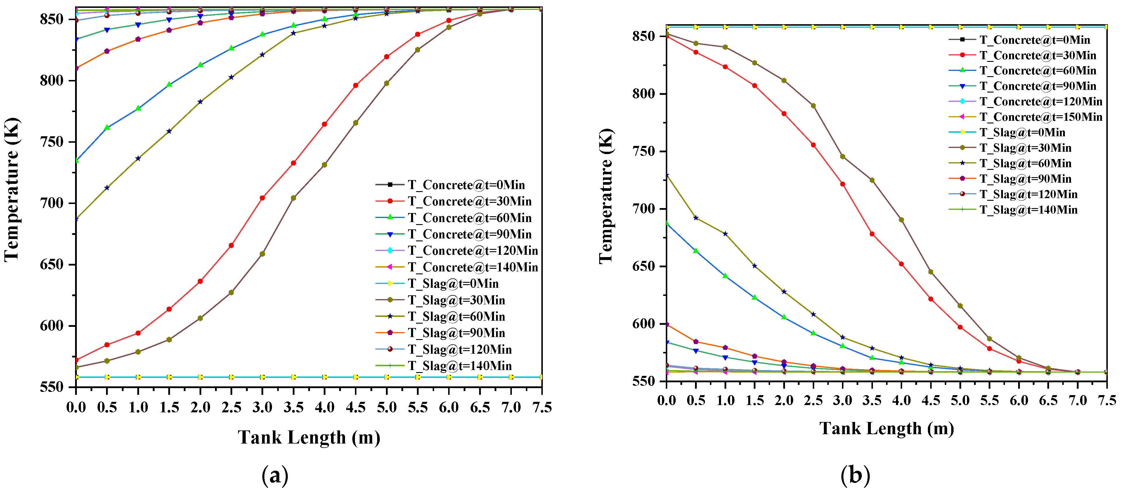
Figure 1a indicates that both concrete and slag samples were rapidly charged and approached the temperature 858 K at the tank position 7.5 m. This was due to the high-temperature difference between the charging material (HTF) and heat source. Therefore, the charging materials require more time (140 min) to be fully charged till reaching tank position 7.5 m, as shown in Figure 1a.
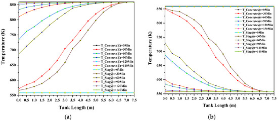
Figure 1.
(a) Charging (b) discharging curves of heat storage material.
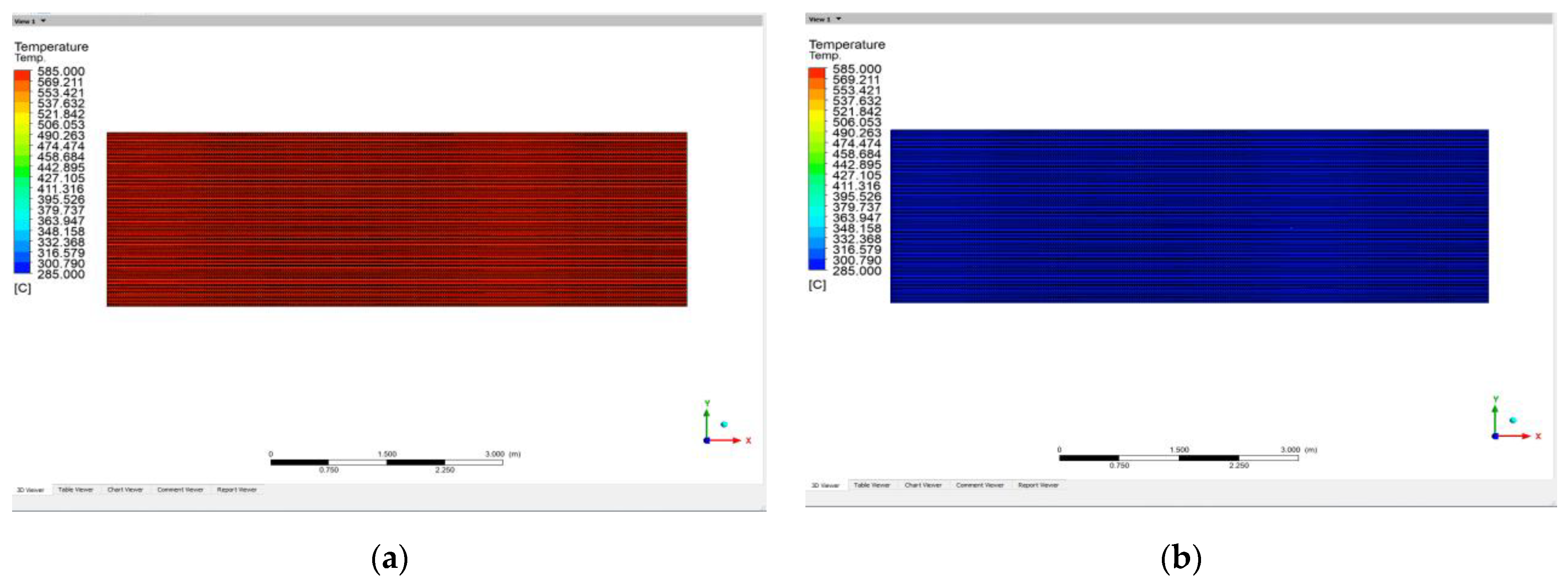
Concrete and slag are both excellent materials for storing sensible heat. Both samples’ charging and discharging rates are ideal for heat storage because of their great heat storage capacity and thermal stability. The charging and discharging profiles of both heat-storing materials were compared, and results showed that the concrete sample charged faster than the slag sample due to its higher heat conductivity. Concrete is more stable and discharges accordingly as a result of its strong heat-storing capacity and thermal stability. Heat storage materials exhibited similar behaviors during the discharge process, quickly completed discharging initially at tank position 7.5 m, then approaching tank position 0 m with the time duration indicated in Figure 1b. Figure 2a shows a fully charged thermal energy storage tank, while Figure 2b shows a fully discharged TES tank for thermal analysis on system software.

Figure 2.
(a) Contours of fully charged and, (b) fully discharged heat storage material as a function of TES tank length.
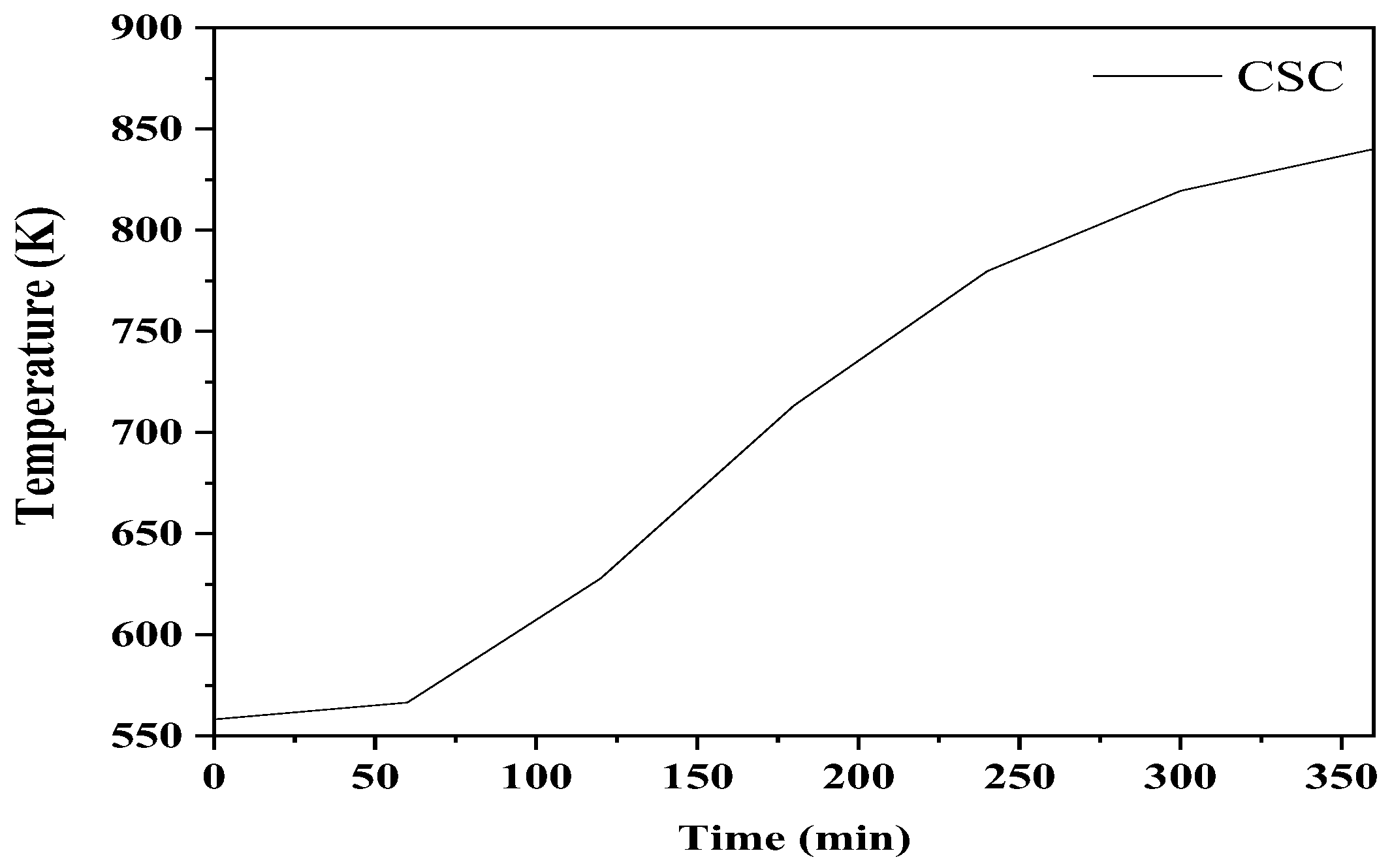
The temperature of the concrete increased with the passage of time until it was completely charged. Figure 3 shows the variation in temperature profiles at x = L/2 as a function of time during the charging process for the slag concrete TES tank. It was observed that the slag-filled TES tank showed better performance with the increase in temperature because thermal conductivity increased due to increased temperature, as shown in Table 2 and Figure 3.

Figure 3.
Variation in temperature profiles at x = L/2.
5. Conclusions
A thermal energy storage tank of 7.5 m height was used in simulations to investigate the thermal conductivity and temperature profile of concrete and slag particles as heat transfer fluids in concrete block. The simulation results show that using concrete as a storage material is a suitable option for sensible heat storage systems due to its quick charging and discharging capability, and therefore, it is a better alternative for implementation in industrial sectors.
Author Contributions
N.A. developed the main idea of the current study. Y.S. performed simulations and wrote the manuscript. J.S. reviewed, edited, and formatted the manuscript. All authors have read and agreed to the published version of the manuscript.
Funding
This research received no external funding.
Data Availability Statement
Not applicable.
Acknowledgments
The authors particularly acknowledge the support of staff, lab engineers, and utilization of facilities at CASEN NUST, Islamabad, for the completion of this research.
Conflicts of Interest
The authors declare no conflict of interest.
References
- Ooka, R.; Ikeda, S. A review on optimization techniques for active thermal energy storage control. Energy Build. 2015, 106, 225–233. [Google Scholar] [CrossRef]
- Zanganeh, G.; Pedretti, A.; Haselbacher, A.; Steinfeld, A. Design of packed bed thermal energy storage systems for high-temperature industrial process heat. Appl. Energy 2015, 137, 812–822. [Google Scholar] [CrossRef]
- Kuravi, S.; Trahan, J.; Goswami, Y.; Jotshi, C.; Stefanakos, E.; Goel, N. Investigation of a high-temperature packed-bed sensible heat thermal energy storage system with large-sized elements. J. Sol. Energy Eng. 2013, 135, 041008. [Google Scholar] [CrossRef]
- Salomoni, V.A.; Majorana, C.E.; Giannuzzi, G.M.; Miliozzi, A.; Di Maggio, R.; Girardi, F.; Mele, D.; Lucentini, M. Thermal storage of sensible heat using concrete modules in solar power plants. Sol. Energy 2014, 103, 303–315. [Google Scholar] [CrossRef]
- Wu, M.; Li, M.; Xu, C.; He, Y.; Tao, W. The impact of concrete structure on the thermal performance of the dual-media thermocline thermal storage tank using concrete as the solid medium. Appl. Energy 2014, 113, 1363–1371. [Google Scholar] [CrossRef]
- Ahmed, N.; Elfeky, K.E.; Lu, L.; Wang, Q.W. Thermal performance analysis of thermocline combined sensible-latent heat storage system using cascaded-layered PCM designs for medium temperature applications. Renew. Energy 2020, 152, 684–697. [Google Scholar] [CrossRef]
- Wang, Y.; Wang, Y.; Li, H.; Zhou, J.; Cen, K. Thermal properties and friction behaviors of slag as energy storage material in concentrate solar power plants. Sol. Energy Mater. Sol. Cells 2018, 182, 21–29. [Google Scholar] [CrossRef]
Publisher’s Note: MDPI stays neutral with regard to jurisdictional claims in published maps and institutional affiliations. |
© 2022 by the authors. Licensee MDPI, Basel, Switzerland. This article is an open access article distributed under the terms and conditions of the Creative Commons Attribution (CC BY) license (https://creativecommons.org/licenses/by/4.0/).