Abstract
This paper focuses on the study of the material and component fatigue parameters of high-performance leaf springs used in the suspension systems of heavy-duty commercial trucks. Currently, there is limited information on the fatigue performance, material characteristics and surface properties of leaf spring components, as manufacturers do not disclose this data. Therefore, production engineers need to conduct extensive experimental testing throughout various phases of product development, consuming significant resources and time. The paper presents well documented experimental procedures on a big variety of testing samples and prototypes with a set methodology providing valuable data such as (a) understanding of the advanced mechanical properties of new leaf-spring production lines, (b) settlement of a well-founded basis for the development of new theoretical tools, and (c) reducing the existing development and testing effort.
1. Introduction
Leaf springs are critical components in suspension systems, widely used in automotive and heavy vehicle applications due to their ability to support variable loads and absorb shocks. Their fatigue performance directly influences vehicle safety, durability, and comfort. Because they endure severe and repeated loading throughout service life, leaf springs are commonly treated using processes such as quenching and tempering, and shot peening to enhance fatigue performance [1,2]. Despite their widespread use and the implementation of such treatments, there remains a significant lack of standardized, accessible data on their fatigue behavior under varying conditions.
Current fatigue studies are often fragmented and scattered across academic and industrial sources. This impedes the development of robust fatigue life models and limits the ability to perform comparative analyses or data-driven design improvements. Other than that, widely used guidelines such as FKM [3] are limited to metals with lower tensile strength, making it an ineffective calculating tool for such high-strength components [4]. To advance the understanding of leaf spring fatigue behavior and reliability fatigue life models, there is a clear need for a centralized, well-curated experimental database.
This paper proposes a structured procedure that has been applied for developing such a database. It includes the basic properties of a typical leaf spring and guidelines for testing procedures, validation and data collection. By promoting this framework, the overall aim is to facilitate more consistent research practices, improve model calibration, and support innovation in suspension system design.
2. Manufacturing & Components Material Testing
Understanding the manufacturing and testing processes of leaf springs is essential, as each step—from thermal treatment to surface conditioning—plays a critical role in determining their fatigue behavior and mechanical performance. The following subsections focus on the most important manufacturing process steps and significant outcomes that should be later considered for the construction of the database.
2.1. Thermal Treatment and Forming
The raw material (mostly Cr-V and Si-Cr-based steels) used for leaf spring production typically has a bainitic-pearlitic microstructure and undergoes several thermal treatments. Steel bars are first heated to temperatures above 900 °C and hot rolled to achieve the desired thickness distribution along the leaf’s length. They are then formed into an elliptical shape to match the spring’s final geometry. Quenching in an oil bath follows, rapidly cooling the leaf and transforming the microstructure into fully martensitic across both the surface and core, thus achieving the required mechanical properties. To reduce brittleness, the leaf is then tempered, allowing the martensitic structure to become tougher and more ductile. However, during the high-temperature phase, carbon atoms diffuse out of the material near the surface, leading to decarburization. This decarburized layer becomes softer due to the reduction in carbon content, altering local mechanical properties. Checking the phase transformation from bainite-pearlite to martensite as well as the extend of the decarburization zone is a significant task and essential before proceeding with further investigations described in the next Section 2.2 and Section 2.3.
2.2. Surface Treatment: Stress Shot Peening (SSP)
After thermal treatment and forming, surface finishing is performed. The leaves are subjected to three-point bending to stretch the tensile surface up to the material’s tensile strength (~1700 MPa), followed by shot peening, while the leaf remains stretched. This combined process, known as Stress Shot Peening (SSP), introduces beneficial compressive residual stresses on the tensile surface, significantly enhancing fatigue life. However, SSP also increases surface roughness [5], particularly in areas critical to fatigue failure. Residual stress distribution is typically measured before and after fatigue testing, commonly by means of X-ray diffraction (XRD) techniques. Due to the major influence of the surface state on the fatigue performance of the spring under operational loading, it is essential to determine the residual stress profile, from the surface towards the core of the spring as well as the surface roughness.
2.3. Mechanical Testing
To characterize the material’s mechanical behavior, tensile tests and macro-hardness (HRC) measurements are conducted. These tests determine the ultimate tensile strength (UTS) and stress–strain characteristics, which are essential for fatigue modeling and quality assurance.
3. Finite Element Analysis
Finite Element Analysis (FEA) is an indispensable task during the design phase to quantify stress levels and identify potential failure-critical regions. A high-quality mesh composed of first-order hexahedral elements, with a length of 3–5 mm, is used to simulate geometry, and an elastic analysis is performed in nonlinear mode to accurately capture contact and material behavior. Considering the high strength of leaf spring steels, the response of the spring remains mainly elastic even at very high loads applied investigated here. The FEA model, Figure 1, replicates the actual operational and/or test setup, a 3-point bending scenario, incorporating realistic boundary conditions, support structures, clamping devices, and loading scenarios as described in [6]. The leaf spring is clamped in the middle by means of clamping plates tightened together via U-bolts, and the leaf spring eyes are supported with rolling bearings. The loading force is applied to the clamping device. The results shown here are major (principal) stresses acting in the longitudinal direction of the leaf spring. The simulation provides the following key outputs:
- (a)
- Principal stress levels for each applied load,
- (b)
- Displacements under corresponding load levels,
- (c)
- Identification of critical areas prone to failure. These critical regions are later monitored during fatigue testing by placing strain gauges on the corresponding surfaces.

Figure 1.
Typical principal stress plot on the tensile surfaces of a 2-leaf spring.
The FEA model enhances the effectiveness of the testing process by offering engineers valuable insights into expected behavior. In particular, the total vertical displacement of the loaded site (central clamping area), the longitudinal displacement of the leaf spring eyes bearings, angle and loads of the supported areas provide the information needed for the setup of the test rig. Moreover, correlating simulation results with physical test data supports fracture analysis and helps pinpoint crack initiation sites and failure modes.
4. Fatigue Testing
To date, the fatigue life of a leaf spring is accurately determined through physical fatigue testing, Figure 2. Prototypes, single leaves and full-scale components are subjected to constant or variable amplitude cyclic loading until failure.
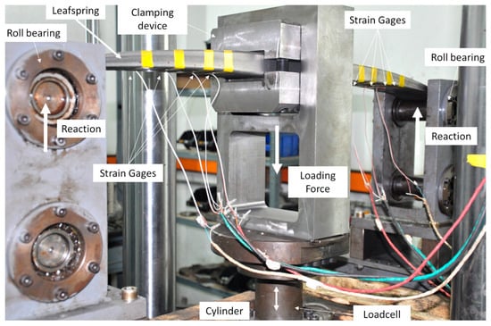
Figure 2.
Cyclic three-point bending testing of a single leaf on a test rig.
Prior to testing, each specimen must be visually inspected, and strain gauges must be applied to surface locations identified as highly stressed based on the Finite Element (FE) analysis stress results acting in longitudinal direction.
While strain gauges measure surface strain during testing, a load cell and a LVDT (Linear Variable Differential Transformer) sensor integrated into the actuator assembly record applied force and displacement, respectively. All measurements are continuously monitored using a data logger and dedicated software until specimen failure occurs.
Fatigue tests are typically strain-controlled, meaning that the load level for each specimen is calibrated based on strain gauge readings. The strain gage’s locations remain the same for each batch’s specimen to reassure the repeatability of the results. The strain gage reading the highest strain has been used as the controlling mode for the test. Notice that the highly stressed location may differ between the various batches, due to the different geometry and loading scenarios. The test is concluded either when the specimen fractures or when it surpasses a predefined fatigue life threshold (e.g., N = 106 cycles). All data is saved, and a detailed analysis of the failure area and fatigue performance is conducted to assess failure modes and correlate with predicted behavior.
5. Fatigue Testing Results Analysis
Data derived from the fatigue testing procedure must be thoroughly analyzed to ensure meaningful and consistent interpretation. The analysis is divided into three main categories: examination of the material’s microstructure, fracture surface analysis, and statistical fatigue life evaluation [7].
5.1. Microstructure Analysis
The microstructure analysis aims to confirm the effectiveness of the thermal treatment, i.e., the full transformation of bainite to (almost) 100% martensite. Furthermore, it helps to categorize each batch by revealing critical features such as the extent of the decarburized layer due to the applied heat treatment, the presence and distribution of carbides, and any inclusions within the steel matrix, all of which may significantly affect fatigue behavior. This information is crucial to further understanding the fracture mechanism and evaluating the material quality and purity. From each manufactured batch of springs, few (usually two to three) specimens are selected and sectioned for metallographic inspection. Figure 3 shows a typical martensitic microstructure image of the surface area of a spring. Therein, the decarburization layer is visible, extending 170 μm from the surface. Some small carbides can also be recognized. Typical contemporary leaf springs consist of almost 100% martensite and have a small decarburization zone until max. 200 μm, depending on the applied thermal treatment.
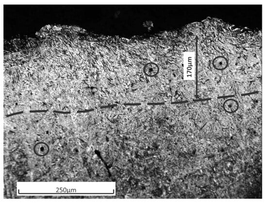
Figure 3.
Decarburization layer of 170 μm.
Notice that, in the case of non-successful martensitic transformation or other errors, such as unallowable pores and inclusions, the whole batch must be rejected from further analyses as the material is softer than the requirements and will eventually lead to lower fatigue life. For the elimination procedure a combination of factors are used, such as microstructure, hardness and in some cases fatigue life in trial batches.
5.2. Fracture Surface Analysis
Figure 4 shows the two fracture surfaces of a broken, 25 mm thick leaf after fatigue testing, exemplarily.
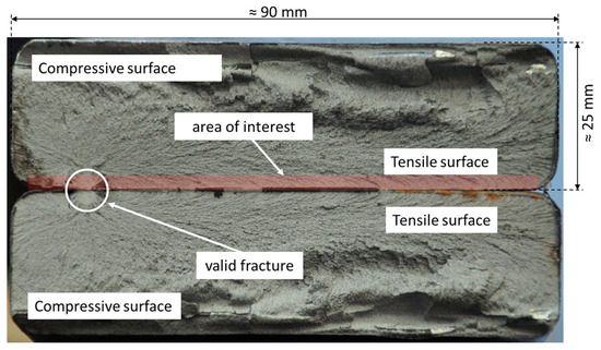
Figure 4.
Typical fracture surfaces and areas of interest (tensile surface area).
The primary area of interest is the tensile surface, where fatigue cracks typically initiate. Crack initiation occurred at the surface of the tensile surface. Notice that in the case of leaf springs, three distinct crack initiation mechanisms are considered: surface initiation, subsurface initiation, and initiation from small inclusions. Other fractures or fractures originating from the profile edges of a specimen should be treated with care, since this may be indication of ineffective SSP process. If so confirmed, e.g., by residual stress measurements, such results should be considered invalid and excluded from further analysis.
5.3. Statistical Analysis of Fatigue Life
This last step includes calculating the S-N (stress vs. number of cycles-to-failure) curves for a group of specimens, corresponding to certain values of probabilities of survival, i.e., 10%, 50% and 90%. Hereby, only valid fatigue life results must be considered, i.e., from specimens not excluded from the previously mentioned analyses. The fatigue life results must cover at least the area of industrial interest, i.e., from N = 105 until N = 106.
Figure 5 shows exemplary statistical evaluation of a leaf spring batch consisting of 17 specimens subject to a constant mean stress σm = 800 MPa, at three stress amplitudes σa = 550, 600 and 650 MPa.
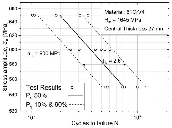
Figure 5.
Fatigue test results and S-N curves for various probabilities of survival.
The circle symbols in Figure 5 stand for the achieved fatigue lives. Linear regression through the test results yields the S-N curve for PS = 50% (black line in Figure 5). The S-N curves for PS = 90% and PS = 10% (dotted lines) have been evaluated by shifting the S-N curve for PS = 50%, taking additionally into account the standard deviation of the results. The S-N curve for PS = 90% constitutes the design curve in industrial applications.
Notice that specimens that do not result in failure within the test limit (runouts) should be treated appropriately. Statistical tools may be used to determine whether the data follows a normal distribution. If the results deviate from a normal distribution, further statistical investigation is conducted to identify and potentially exclude outliers.
6. Database
Over the past two decades, more than 500 leaf springs—including prototypes, serial components, and large-scale specimens have been fatigue-tested to failure at the Laboratory of Machine Elements and Machine Design of the Aristotle University of Thessaloniki. These specimens represented a wide range of geometries, thicknesses, and profiles sourced from various manufacturers worldwide. Testing was conducted under different stress amplitudes and mean stresses to simulate diverse service conditions.
The resulting dataset captures geometrical, material and manufacturing characteristics and a broad spectrum of fatigue behavior, with recorded failure mechanisms including surface initiation, subsurface initiation, edge-related fractures, and inclusion-driven failures. Fatigue lives ranged from low-cycle failures to long-life specimens (runouts). After detailed analysis, as described in the above sections, some results were excluded as statistical outliers.
Following the strict qualification criteria described above, 336 specimens were finally identified as equivalent to contemporary OEM leaf spring components. These qualified specimens are grouped into 31 distinct batches, each representing different combinations of material grade, thickness, thermal treatment processes, and stress shot peening offering a comprehensive representation of current industrial production practices. A tabular overview of the selected dataset is presented Table 1 below. Therein, Rm stands for the tensile strength in MPa. Rz represents the arithmetic mean roughness value in μm, and HRC is the unitless Rockwell-C hardness.

Table 1.
Tabular overview of the created dataset.
7. Conclusions
The fatigue behavior of leaf springs plays a critical role in the reliability and safety of suspension systems, yet standardized and accessible experimental data remain scarce. This paper presents a comprehensive procedure for generating a robust fatigue life database for leaf springs, encompassing detailed manufacturing practices, finite element modeling, fatigue testing, and data analysis. By systematically integrating experimental results with FEA predictions and material characterization, the procedure ensures consistency, reliability, and traceability across a wide range of spring designs and testing conditions.
The resulting dataset, derived from over 500 tested specimens—336 of which were qualified as representative of current OEM standards—offers valuable insight into the fatigue performance of leaf springs under diverse conditions. This work lays the foundation for a standardized, expandable database that can serve as a benchmark for researchers, manufacturers, and engineers. It supports the development of more accurate fatigue life prediction models, enhances design practices, and contributes to the advancement of safer and more efficient suspension components.
Author Contributions
Conceptualization, E.G.; Methodology, E.G.; Validation, P.A., C.G. and E.G.; Formal Analysis, E.G., P.A. and C.G.; Investigation, C.G., E.G. and P.A.; Resources, G.S.; Data Curation, G.S.; Writing—Original Draft Preparation, E.G.; Writing—Review and Editing, G.S.; Visualization, E.G., P.A. and C.G.; Supervision, G.S.; Project Administration, G.S. All authors have read and agreed to the published version of the manuscript.
Funding
This research has received no external funding.
Institutional Review Board Statement
Not applicable.
Informed Consent Statement
Not applicable.
Data Availability Statement
The raw data supporting the conclusions of this article will be made available by the authors on request.
Acknowledgments
BETA CAE Systems is gratefully acknowledged by all authors for the provision of ANSA and META v24.1.2 software. The Center for Interdisciplinary Research and Innovation (CIRI AUTH—ΚΕDΕΚ, DRAM Group) is gratefully acknowledged.
Conflicts of Interest
The authors declare no conflicts of interest.
References
- Lai, C.; Huang, W.; Li, S.; Liu, T.; Lv, R.; Tang, X.; Yu, J. Effects of Quenching and Tempering Heat Treatment on Microstructure, Mechanical Properties, and Fatigue Crack Growth Behavior of 51CrV4 Spring Steel. Mater. Res. Express 2021, 8, 096514. [Google Scholar] [CrossRef]
- Farrahi, G.H.; Lebrijn, J.L.; Couratin, D. Effect of Shot Peening on Residual Stress and Fatigue Life of a Spring Steel. Fatigue Fract. Eng. Mater. Struct. 1995, 18, 211–220. [Google Scholar] [CrossRef]
- Forschungskuratorium Maschinenbau (Ed.) Analytical Strength Assessment of Components in Mechanical Engineering: FKM-Guideline, 5th ed.; FKM-Guideline; VDMA Verl: Frankfurt am Main, Germany, 2003; ISBN 978-3-8163-0425-8. [Google Scholar]
- Giannakis, E.; Savaidis, G. Fatigue Assessment of High Strength Leaf Springs Based on the FKM Guideline: Bewertung Der Schwingfestigkeit von Hochfesten Blattfedern Auf Basis Der FKM-Richtlinie. Mater. Werkst. 2016, 47, 897–903. [Google Scholar] [CrossRef]
- ISO 21920-2:2021; Geometrical Product Specifications (GPS)—Surface Texture: Profile, Part 2: Terms, Definitions and Surface Texture Parameters. ISO: Geneva, Switzerland, 2021. Available online: https://www.iso.org/standard/72226.html (accessed on 26 April 2023).
- Malikoutsakis, M.; Savaidis, G.; Savaidis, A.; Ertelt, C.; Schwaiger, F. Design, Analysis and Multi-Disciplinary Optimization of High-Performance Front Leaf Springs. Theor. Appl. Fract. Mech. 2016, 83, 42–50. [Google Scholar] [CrossRef]
- Stephens, R.I.; Fatemi, A.; Stephens, R.R.; Henry, O. Fuchs Metal Fatigue in Engineering, 2nd ed.; Wiley: New York, NY, USA, 2000; ISBN 978-0-471-51059-9. [Google Scholar]
Disclaimer/Publisher’s Note: The statements, opinions and data contained in all publications are solely those of the individual author(s) and contributor(s) and not of MDPI and/or the editor(s). MDPI and/or the editor(s) disclaim responsibility for any injury to people or property resulting from any ideas, methods, instructions or products referred to in the content. |
© 2025 by the authors. Licensee MDPI, Basel, Switzerland. This article is an open access article distributed under the terms and conditions of the Creative Commons Attribution (CC BY) license (https://creativecommons.org/licenses/by/4.0/).