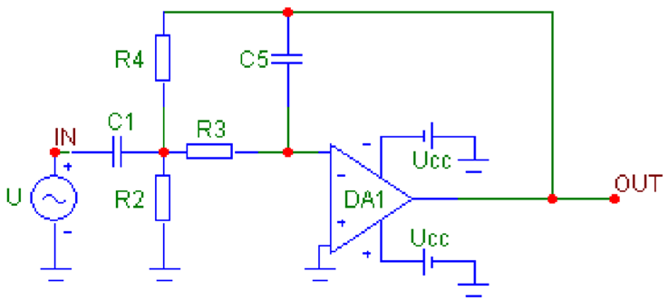
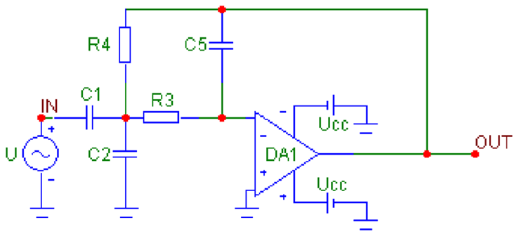
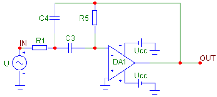
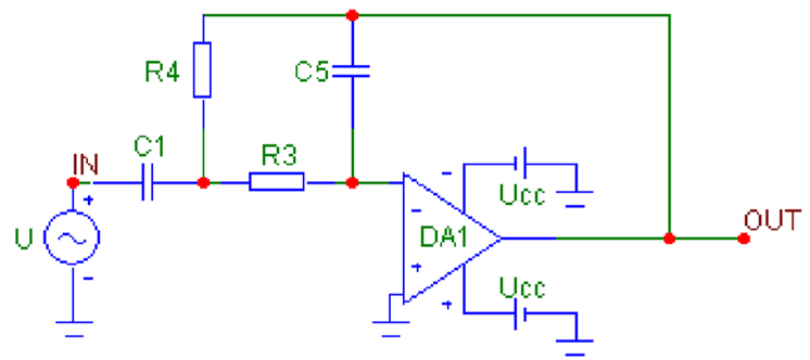
Abstract
This paper offers a comprehensive methodology for the synthesis and analysis of active filters, including low-pass, high-pass, and band-pass configurations, utilizing operational amplifiers and multi-loop negative feedback systems. The approach involves deriving explicit analytical expressions for the design and optimization of eight distinct filter circuit solutions: one low-pass, one high-pass, and six band-pass filters with varying specifications. These derivations include the calculation of normalized and denormalized component values (resistors and capacitors), enabling precise tuning and practical implementation of the filters. Furthermore, the methodology encompasses the determination of key filter parameters such as passband gain, pole quality factor (Q-factor), and cut-off/center frequency, after selecting standard resistor and capacitor values suitable for the target application. The analytical framework facilitates a systematic approach to filter design, ensuring that the resulting circuits meet specific frequency response criteria while maintaining optimal stability and performance. The proposed methodology can be effectively applied in the development of various active filtering systems for signal processing, communication, and instrumentation, offering engineers a reliable foundation for designing high-performance, tailored filter solutions.
1. Introduction
Active filters are circuits that use an operational amplifier (op-amp) as the active component, along with resistors and capacitors, to achieve LRC-like filter performance at low frequencies [1,2,3].
Operational amplifiers with negative feedback can operate in three configurations: non-inverting amplifier, inverting amplifier, and voltage follower. The primary purpose of negative feedback is to minimize the voltage difference between the inverting and non-inverting inputs, resulting in an output voltage that stays within the limits set by the DC voltages that bias the internal transistors of the operational amplifier, ensuring it functions in the forward active mode [4,5].
In telecommunications, band-pass filters (BPFs) are used within the audio frequency range (0 Hz to 20 kHz) for applications such as speech processing and modems. In the high-frequency range (several hundred MHz), BPFs are employed for channel selection in telephone central offices. Data acquisition systems typically require anti-aliasing low-pass filters (LPFs) and low-pass noise filters during their initial signal conditioning stages. Band-stop filters (BSFs), also referred to as notch or rejection filters, are commonly utilized to eliminate the 60 Hz line frequency and high-frequency components in power supply systems [1,2].
The “Communication Circuits” course [5,6,7,8] for bachelor students specializing in “Internet and Mobile Communications” in their fourth semester at the University of Ruse is designed to cover active filters using an operational amplifier. This includes studying single-loop negative feedback methods, as well as exploring multi-loop negative feedback, which are the focus of this research publication, and voltage-controlled voltage sources, among other topics.
The synthesis of active filters involves three key stages: approximation, implementation, and optimization [6,8,9].
The approximation phase focuses on determining the transfer function that meets specific filter characteristics, such as frequency response, phase response, impulse response, and transient response, to a specified level of accuracy. Typically, the most common practical task in this phase is to approximate a given frequency response.
The transfer function is the Laplace transform of the impulse response and is given in operator form as a fractional-rational function of p:
The coefficients and are real numbers and are functions of the circuit parameters (R, C, L, and others). It is necessary to always satisfy the condition The values of p for which the polynomial in the numerator is equal to zero are called zeros of the transfer characteristic. The values of p for which the polynomial in the denominator is equal to zero are called poles of the transfer characteristic. For second-order filters (at the quality factor is defined as
As a result of the approximation, normalized transfer functions are obtained, with the normalization being by frequency and resistance. Normalization is expressed in changing the measuring units of the parameters of the circuit elements, with the values of the normalizing resistance and frequency being chosen as units.
Depending on the passed frequency band of the filter, the individual types of filters of I and II order have transfer functions, the type of which is given in Table 1.

Table 1.
Transfer functions of individual types of I and II order filters.
It should be noted that band-pass and band-stop (notch) filters can only be of second and higher order. In Table 1, the following notations are introduced:
—cut-off circular frequency for low-pass and high-pass filters;
—center circular frequency for band-pass and band-stop (notch) filters; it is determined by the formula: where and are the two cut-off circular frequencies defining the passband for the band-pass filter or the stopband for the band-stop filter.
—proportionality coefficient, which reflects the gain in the passband;
—pole quality factor (for brevity, just called quality factor). Sometimes, instead of the pole quality factor, its reciprocal value, called the oscillation coefficient, is used.
Active filters can be implemented through various methods. One approach involves a fixed circuit structure where the positions of the operational amplifiers and passive components are predetermined. From the circuit analysis, the necessary conditions for the passive elements can be established. The cascade connection method is the most prevalent technique, where the circuit’s transfer function is derived incrementally by applying first and second-order elementary functions. This paper outlines a method for creating second-order low-pass, high-pass, and band-pass filters using operational amplifiers with multi-loop negative feedback.
2. Synthesis and Analysis of Active Filters with a Multi-Loop Negative Feedback
Figure 1 shows the circuit of an active filter with an operational amplifier, implemented according to the multi-loop negative feedback model.
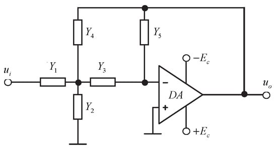
Figure 1.
Scheme of an active filter with an operational amplifier, implemented according to the multi-loop negative feedback model.
In this case, the voltage transfer function at idle operation of the circuit is:
The synthesis of the filter is reduced to the selection of bipoles whose conductivities can realize the given transfer function.
Algorithm for synthesis and analysis of second-order active filters with a single operational amplifier according to the multi-loop negative feedback model:
When designing second-order active filters with a single operational amplifier according to the multi-loop negative feedback model, the following is specified [8]:
Normalized transfer function of the filter: where is equal to: (for low-pass filters, LPFs), (for high-pass filters, HPFs), and (for band-pass filters, BPFs); normalizing resistance , cut-off frequency (for LPFs and HPFs) or center frequency (for BPFs).
1. Determination of the type of conductances to realize the specified voltage transfer function (for LPFs and HPFs) or justification of the band-pass nature of the transfer function for a given structure of the synthesized filter (for BPFs) [8].
Using signal graph theory [10], the expression for the transfer function of an active filter with a single operational amplifier using the multi-loop negative feedback method, in idle mode, can be derived and expressed by Equation (2).
Each of the conductances can be purely active, of a resistor or purely capacitive, of a capacitor The goal is to determine the type of each of the conductances.
- 🗸
- For LPFs:
In the case of the LPFs, in the numerator of , which is given by condition, there is only a free term , which means that and are necessarily purely active. Therefore, and . In this case, the denominator of will be: It can be seen that in order for a term , to be present in it, must necessarily be of the type and then the denominator will be:
All possible combinations (four in number) for the remaining two conductivities and , whose type must be determined, are written in Table 2. For each of the combinations, the denominator of , as well as the missing degree of p in it, is recorded [6,7,8].

Table 2.
Determining the type of conductivities and for the LPFs.
It can be seen that only in the case when and , in the denominator of there is no missing degree of , which is also required by condition, and the denominator of will be: Therefore, after the reasoning made, the transfer function of the LPF can be written:
- 🗸
- For HPFs:
In the case of the HPFs, in the numerator of , which is given by condition, only , is present, which means that and are necessarily purely capacitive. Therefore, and In this case, the denominator of will be: It can be seen that in order for a term to be present in it, must necessarily be of the type and then the denominator will be:
All possible combinations (four in number) for the remaining two conductivities and , whose type must be determined, are written in Table 3. For each of the combinations, the denominator of , as well as the missing degree of p in it, is recorded.

Table 3.
Determining the type of conductivities and for the HPFs.
It can be seen that only in the case when and in the denominator of there is no missing degree of p, which is also required by condition, and the denominator of will be: Therefore, after the reasoning made, the transfer function of the HPF can be written in the form [8]:
- 🗸
- For BPFs—there are 6 possible circuit configurations, described in Table 4, which will be derived and summarized below.
 Table 4. Possible circuit configurations for the BPFs.
In the case of the BPFs, in the numerator of , which is given by condition, only is present, which means that and are necessarily of opposite character, i.e., two cases are possible: I. and II. and
- Case I. and
In this case, the denominator of will be: It can be seen that in order for a term to be present in it, must necessarily be of the type and then the denominator will be:
All possible combinations (four in number) for the remaining two conductivities and , whose type must be determined, are written in Table 5. For each of the combinations, the denominator of , as well as the missing degree of p in it, is recorded [8].

Table 5.
Determining the type of conductivities and for the BPFs (for case I).
It can be seen that in two of the cases when: (1) and or (2) and in the denominator of there is no missing degree of , which is also required by the condition. This conclusion suggests that in this case the character of is irrelevant, which means that it may even be missing, i.e., , in which case the 4-component scheme of a bandpass filter with R-input is obtained. In Table 5 this is reflected by the last row. Therefore, after the reasoning made, the following expressions can be written for the transfer function of the BPFs for the three possible configurations with R-input:
- (1)
- and : ;
- (2)
- and :
- (3)
- and :
- Case II. and
In this case, the denominator of will be: It can be seen that in order for a term to be present in it, must necessarily be of the type and then the denominator will be:
All possible combinations (four in number) for the remaining two conductivities and , whose type must be determined, are written in Table 6. For each of the combinations, the denominator of , as well as the missing degree of p in it, is recorded.

Table 6.
Determining the type of conductivities and for the BPFs (for case II).
It can be seen that in two of the cases when: (1) and or (2) and , in the denominator of there is no missing degree of p, which is also required by the condition. This conclusion suggests that in this case the character of is irrelevant, which means that it may even be missing, i.e., , in which case the 4-component scheme of a bandpass filter with C-input is obtained. This is reflected by the last row in Table 6. Therefore, after the reasoning made, the following expressions can be written for the transfer function of the BPFs for the three possible configurations with C-input [8]:
- (1)
- and : ;
- (2)
- and : ;
- (3)
- and : .
Note: Band-stop filters (BSFs) cannot be synthesized using the multi-loop negative feedback operational amplifier method!
In summary to point 1 of the algorithm:
- 🗸
- For LPFs:
- 🗸
- For HPFs:
- 🗸
- For BPFs—type I:
- 🗸
- For BPFs—type II:
- 🗸
- For BPFs—type III:
- 🗸
- For BPFs—type IV:
- 🗸
- For BPFs—type V:
- 🗸
- For BPFs—type VI:
2. Derivation of the expressions for calculating the normalized values of the elements of the synthesized filter after equating the coefficients in front of the same powers of p in the numerator and in the denominator of the given voltage transfer function and the general form of the corresponding transfer function (Table 1)—by solving a system of four equations with five unknowns (for LPFs, HPFs and BPFs according to a 5-component scheme, assuming the additional condition ) or with four unknowns (for BPFs according to a 4-component scheme, in which the conductivity is absent) [8].
- 🗸
- for LPFs:
The system is solved under the assumption that .
From the last equation of the system
- 🗸
- For HPFs:
The system is solved under the assumption that .
From the second equation of the system .
- 🗸
- For BPFs—type I:
The system is solved under the assumption that .
From the second equation of the system .
- 🗸
- For BPFs—type II:
The system is solved under the assumption that .
From the second equation of the system .
- 🗸
- For BPFs—type III:
The system is solved under the assumption that .
From the fourth equation of the system .
- 🗸
- For BPFs—type IV:
The system is solved under the assumption that .
From the fourth equation of the system .
- 🗸
- For BPFs—type V:
- 🗸
- For BPFs—type VI:
3. Calculation of the normalized values of the elements of the synthesized filter.
Note: The normalized values of the elements of the synthesized filter are calculated using the formulas derived in point 2 of the algorithm. The formulas in the general case, for a transfer function: are given below. The method of derivation is analogous to that in point 2, where the formulas are simplified under the assumption: and , which case is considered by students during classes in the course “Communication Circuits”.
- 🗸
- For LPFs—
- 🗸
- For HPFs—
- 🗸
- For BPFs—there are six varieties [6,7,8]:
- Type I (R-input, 5-component circuit, condition: —
- Type II (R-input, 5-component circuit, condition: —
- Type III (C-input, 5-component circuit, condition: —
- Type IV (C-input, 5-component circuit, condition: —
- Type V (R-input, 4-component circuit, condition: — —missing,
- Type VI (C-input, 4-component circuit, condition: — —missing,
4. Calculation of the normalizing circular frequency :
- 🗸
- For LPFs and HPFs—
- 🗸
- For BPFs—
5. Calculation of the denormalized values of the elements of the bipoles:
- 🗸
- for resistors—the obtained resistance values for i = 1…5 are multiplied by the normalizing resistance
- 🗸
- for capacitors—the obtained capacitance values are divided by the product
6. Choosing standard values of the parameters of the filter elements from the E-24 scale:
E-24 Standard values for resistors and capacitors : 1.0, 1.1, 1.2, 1.3, 1.5, 1.6, 1.8, 2.0, 2.2, 2.4, 2.7, 3.0, 3.3, 3.6, 3.9, 4.3, 4.7, 5.1, 5.6, 6.2, 6.8, 7.5, 8.2 and 9.1; multiplied by
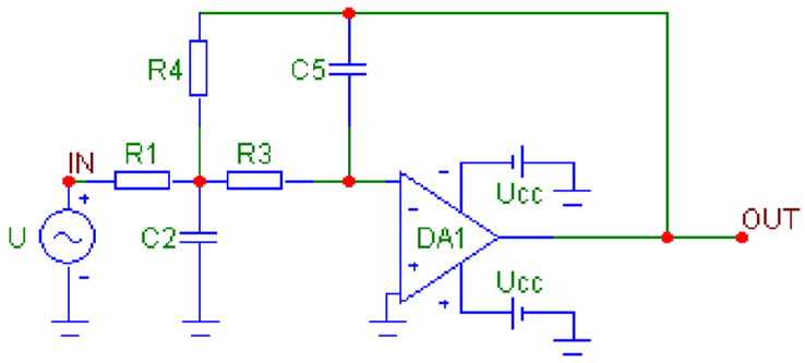
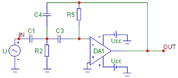
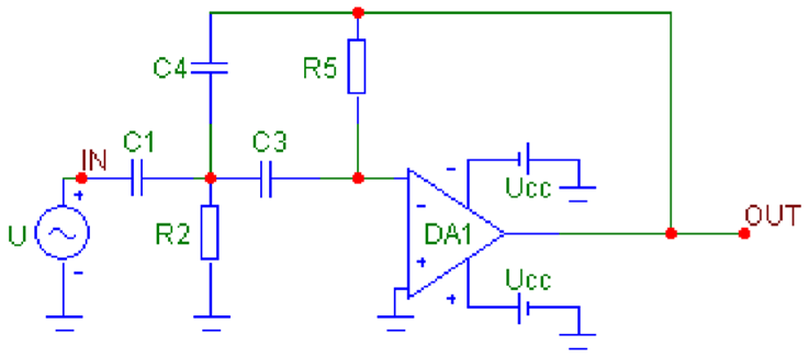
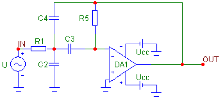
7. Drawing the schematic of the synthesized filter (Table 7).

Table 7.
Circuits of active filters with one operational amplifier using the multi-loop negative feedback method.
8. Deriving the voltage transfer functions for the LPFs, HPFs and BPFs from Table 7, using signal graph theory [10]:
- 🗸
- For LPFs—
- 🗸
- For HPFs—
- 🗸
- For BPFs—for the six possible circuit solutions:
- Type I—
- Type II—
- Type III—
- Type IV—
- Type V—
- Type VI—
9. Derivation of the expressions for the passband gain , the pole quality factor and the cutoff frequency (of the LPFs and HPFs) or the center frequency (of the BPFs) after comparing the expressions for the transfer functions (point 7) and the theoretical expressions for the transfer functions (Table 1). For this purpose, it is necessary to transform the transfer function of the second-order filter to the form indicated in Table 1, i.e., the coefficient in front of the highest power of p in the denominator must be 1. The expression for the cutoff frequency (of the LPFs and HPFs) or the center frequency (of the BPFs) is obtained after equating the coefficients in front of the free term in the denominator. The expression for the pole quality factor is obtained after equating the coefficients in front of p in the denominator. The expression for the passband gain is obtained after equating the coefficients in the numerator [8].
- 🗸
- For LPFs:
Converting the transfer function of LPFs to the form specified in Table 1:
General form of the transfer function of the LPFs (Table 1): .
Comparing coefficients before the same powers of p in the numerator and denominator:
Before in the denominator
Before in the denominator
Before in the numerator
- 🗸
- For HPFs:
Converting the transfer function of HPFs to the form specified in Table 1:
General form of the transfer function of the HPFs (Table 1): .
Comparing coefficients before the same powers of p in the numerator and denominator:
Before in the denominator
Before in the denominator
Before in the numerator
For the remaining configurations of second-order bandpass filters, the general form of the transfer function is taken into account:
- 🗸
- for BPFs—type I:
Converting the transfer function of BPFs to the form specified in Table 1:
Comparing the coefficients before the same powers of p in the numerator and denominator:
- 🗸
- for BPFs—type II:
Converting the transfer function of BPFs to the form specified in Table 1:
Comparing the coefficients before the same powers of p in the numerator and denominator:
- 🗸
- for BPFs—type III:
Converting the transfer function of BPFs to the form specified in Table 1:
Comparing the coefficients before the same powers of p in the numerator and denominator:
- 🗸
- for BPFs—type IV:
Converting the transfer function of BPFs to the form specified in Table 1:
Comparing the coefficients before the same powers of p in the numerator and denominator:
- 🗸
- for BPFs—type V:
Converting the transfer function of BPFs to the form specified in Table 1:
Comparing the coefficients before the same powers of p in the numerator and denominator:
- 🗸
- for BPFs—type VI:
Converting the transfer function of BPFs to the form specified in Table 1:
Comparing the coefficients before the same powers of p in the numerator and denominator:
10. Calculation of the passband gain , pole quality factor and cutoff frequency (for LPFs and HPFs) or center frequency (for BPFs) after selecting standard element values [8].
- 🗸
- for LPFs:
- 🗸
- For HPFs:
- 🗸
- For BPFs—type I:
- 🗸
- For BPFs—type II:
- 🗸
- For BPFs—type III:
- 🗸
- For BPFs—type IV:
- 🗸
- For BPFs—type V:
- 🗸
- For BPFs—type VI:
11. Simulation study of the synthesized filter using the MicroCAP [11,12] or Multisim [13] software product—plotting the amplitude-frequency characteristics (magnitude response), determining the parameters and (resp. ) from the corresponding response.
The synthesis and analysis methodology described in the publication is implemented in a developed MS Excel-based module. Figure 2 shows a module for synthesizing and analyzing a bandpass filter of type VI—the calculated normalized and denormalized values of the elements, the selected standard values of the resistors and capacitors, and the calculation of the main parameters after the selection of the standard values are visible. After the selection of standard values of the resistors and capacitors, the circuit of the designed filter is implemented in MicroCAP and is studied. The amplitude-frequency characteristics (magnitude response) of the designed filter are shown in Figure 3, with the maximum of the characteristics marked, and Figure 4 shows the two cut-off frequencies of the passband, with a drop of 3 dB. From these characteristics, the width of the passed frequency band, the quality factor, and the gain in the passband can be determined as follows:
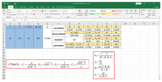
Figure 2.
MS Excel-based module for synthesis and analysis of active filters according to the proposed methodology.
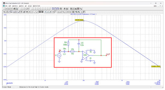
Figure 3.
Simulation study in MicroCAP of the synthesized active filter—determining the center frequency.
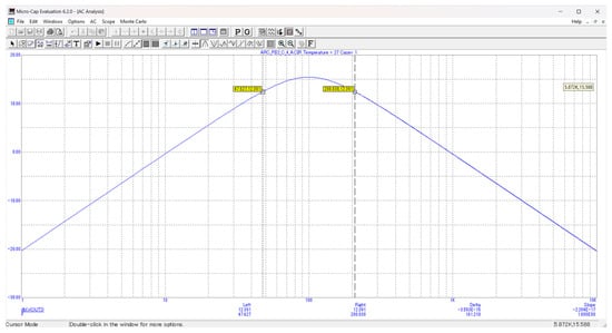
Figure 4.
Simulation study in MicroCAP of the synthesized active filter—determining the cut-off frequencies.
(from Figure 3).
(from Figure 4).
In this case, a band-pass filter of type VI is synthesized using the normalized transfer function normalizing resistance and center frequency
3. Conclusions
This paper presents a detailed methodology for synthesizing and analyzing low-pass, high-pass, and band-pass active filters with an operational amplifier and multi-loop negative feedback. Expressions for the dimensioning of 8 filter circuit solutions are derived, including the determination of the normalized and denormalized values of the filter elements, and the determination of the filter parameters such as the passband gain, pole quality factor and cut-off/center frequency of the filter after choosing standard values of the resistors and capacitors in the circuit.
MS Excel-based applications for synthesizing and analyzing the filters under consideration are developed based on the proposed methodology. The synthesized filters are implemented and studied in MicroCAP 6 and the results are compared to the calculated ones.
The advantages of the circuits with a single op-amp with a multi-loop feedback are: a) they are as simple as possible—they contain only five (and in some cases four) passive elements; b) they have a very small output resistance, set only by the output resistance of the op-amp with feedback, which tends to zero, and this provides ideal conditions for a cascade-decoupled implementation according to the principle of “high-impedance input to low-impedance output”.
The disadvantages of the circuits with a single op-amp with a multi-loop feedback are: (a) difficulties in implementing large and ; (b) poles of attenuation for real frequencies cannot be implemented (zeros of the transfer function on the imaginary axis) [9].
Like all single-op circuits, these do not allow independent adjustment of , resp. , , and . The three parameters usually depend on all elements in the circuit, and any attempt to adjust a given parameter leads to a change in the other two.
Author Contributions
All authors contributed equally to this work. All authors have read and agreed to the published version of the manuscript.
Funding
This study is financed by the European Union NextGenerationEU, through the National Recovery and Resilience Plan of the Republic of Bulgaria, project No. BGRRP-2.013-0001-C03.
Institutional Review Board Statement
Not applicable.
Informed Consent Statement
Not applicable.
Data Availability Statement
No new data were created or analyzed in this study.
Conflicts of Interest
The authors declare no conflicts of interest.
Abbreviations
The following abbreviations are used in this manuscript:
| LPFs | Low-pass filters |
| HPFs | High-pass filters |
| BPFs | Band-pass filters |
| BSFs | Band-stop filters |
References
- Kugelstadt, T. Chapter 16—Active Filter Design Techniques; Texas Instruments: Dallas, TX, USA, 2001. [Google Scholar]
- Winder, S. Analog and Digital Filter Design, 2nd ed.; Newnes, Elsevier Science (USA): San Diego, CA, USA, 2002; p. 458. [Google Scholar]
- Chen, W.-K. The Circuits and Filters Handbook; Chen, W.-K., Ed.; CRC Press LLC: Boca Raton, FL, USA, 2003; p. 2881. [Google Scholar]
- Elaraby, N. A Detailed Lesson on Operational Amplifiers—Negative Feedback. In Proceedings of the Spring 2017 Mid-Atlantic ASEE Conference, Baltimore, MD, USA, 7–8 April 2017; p. 20849. [Google Scholar]
- E-Learning Shell. Available online: http://ecet.ecs.uni-ruse.bg/else (accessed on 23 April 2025).
- Puentes-Conde, G.M.; Sifuentes, E.; Molina, J.; Enríquez-Aguilera, F.; Bravo, G.; Enríquez, G.N. Direct Interface Circuits for Resistive, Capacitive, and Inductive Sensors: A Review. Electronics 2025, 14, 2393. [Google Scholar] [CrossRef]
- Amineh, R.K. RF, Microwave, and Millimeter Wave Devices and Circuits and Their Applications. Electronics 2025, 14, 2844. [Google Scholar] [CrossRef]
- Borodzhieva, A. Communication Circuits. Textbook; Academic Publishing House “University of Ruse”: Ruse, Bulgaria, 2024; 160p, ISBN 978-954-712-943-6. (In Bulgarian) [Google Scholar]
- Pantoli, L.; Leuzzi, G.; Deborgies, F.; Jankovic, P.; Vitulli, F. A Survey of MMIC Active Filters. Electronics 2021, 10, 1680. [Google Scholar] [CrossRef]
- Boyanov, J.; Shoikova, E. Theory of Electronic Circuits; Tehnika: Sofia, Bulgaria, 1995. (In Bulgarian) [Google Scholar]
- Spectrum Software. Available online: http://www.spectrum-soft.com/index.shtm (accessed on 23 April 2025).
- Micro-Cap. Available online: https://micro-cap.informer.com/12.0/ (accessed on 23 April 2025).
- Multisim. Available online: https://www.multisim.com/ (accessed on 23 April 2025).
Disclaimer/Publisher’s Note: The statements, opinions and data contained in all publications are solely those of the individual author(s) and contributor(s) and not of MDPI and/or the editor(s). MDPI and/or the editor(s) disclaim responsibility for any injury to people or property resulting from any ideas, methods, instructions or products referred to in the content. |
© 2025 by the authors. Licensee MDPI, Basel, Switzerland. This article is an open access article distributed under the terms and conditions of the Creative Commons Attribution (CC BY) license (https://creativecommons.org/licenses/by/4.0/).
