Abstract
This paper analyzes the physics of the TMD-Inerter for harmonic vibrations. The basic TMD-Inerter layout is assumed, where the inerter is installed between the TMD mass and the structural mass. For harmonic vibrations, the inerter force can be formulated as a function of terminal displacements. This formulation demonstrates that the inerter force is, in fact, a negative stiffness force with frequency-dependent negative stiffness coefficient. Based on this finding, the optimal stiffness tuning of the TMD-Inerter is derived. As this stiffness tuning can only be realized by a controlled actuator, the tuning of the spring of the TMD-Inerter is presented. As this spring is a passive element, its optimum tuning must be made at a selected frequency of vibration. It is shown that the average of the TMD natural frequency and structural eigenfrequency leads to a close to optimal spring tuning. This approach needs to be combined with increased damping of the TMD-Inerter to minimize the structural displacement response. Despite the close to optimal tunings of stiffness and damping, the resulting primary structure displacement response is approximately 41.6% greater than that due to the classical TMD. The reason for this lies in the fact that the passive spring of the TMD-Inerter cannot compensate for the frequency-dependent negative stiffness of the inerter within the entire frequency range.
1. Introduction
The Tuned Mass Damper (TMD [,]) represents the common device to reduce wind-induced vibrations in tall buildings to the acceptable acceleration levels of the 1-year and 10-year return period winds []. In most projects, the biggest challenge in TMD design for tall building damping is the limited spatial dimensions of the TMD room due to economic reasons. To reduce the length of a single pendulum TMD, the concepts of the folded pendulum and compound pendulum exist. However, the limitations in the plane direction may be critical. These dimensions must be large enough for the size of the TMD mass, the relative motion of the oil hydraulic dampers, and the end damper system to avoid collisions between the pendulum mass and the surrounding walls. Reducing the dimensions of the TMD mass in the plane direction is not an option, as this will reduce the TMD mass and, consequently, the required structural damping will not be achieved.
In this regard, the inerter, as a device that exerts a force in proportion to the relative acceleration of its terminals, has gained much attraction. A good overview of inerter applications can be found in the review article []. The idea is that the inertia force of the inerter could virtually augment the TMD mass, which would allow reducing the physical TMD mass such that it fits into the given spatial dimensions of the TMD room. For this, the inerter would be installed between the TMD mass and the structural mass next to the TMD mass, i.e., to the floor of the TMD room. Some of the first publications dealing with the use of the inerter for tall building damping analyzed the above-described configuration where the inerter is grounded to the primary structure next to the TMD [,,]. For this configuration, approximate design rules of the TMD-Inerter stiffness and damping were derived. Configurations where the inerter was grounded on the primary structure farther away from the TMD, i.e., on stories far below the top story, were investigated, as well, because the simulations pointed out that the TMD-Inerter may improve the structural damping for such configurations [,,,,]. In addition to these classical TMD-Inerter configurations, where the inerter is installed between TMD mass and structural mass, various other TMD-Inerter layouts were analyzed where the inerter is connected in series with and parallel to spring and dashpot damping elements [,,,]. The aim of these configurations is to produce an additional degree of freedom by the inerter. The use of the TMD-Inerter against seismic excitation has been investigated as well []. As the realization of these configurations would be a very challenging task and the related high costs would question such systems, these configurations are not further discussed here.
For the classical TMD-Inerter layout, it is crucial to realize that the inerter is a device that—by definition—produces a force, which is in proportion to the relative acceleration of both terminals. Newton’s second law states that the inertia force is in proportion to the absolute acceleration of the mass. Therefore, the question arises whether the conceptual idea is correct that the inerter force does increase the TMD mass. This fundamental question is investigated in this paper. Assuming harmonic terminal accelerations, it is shown that the inerter produces a negative stiffness force with a frequency-dependent negative stiffness coefficient. The most realistic TMD-Inerter layout is considered where the inerter is grounded to the primary structure next to the TMD. This configuration could be realized by grounding the inerter to the floor of the TMD room. Active and passive compensation strategies for the design of the TMD-Inerter stiffness in combination with optimized TMD-Inerter damping are provided. The resulting structural displacement responses are discussed, and conclusions are drawn.
2. Modeling of the Primary Structure with TMD-Inerter
2.1. Equations of Motion for Harmonic Vibrations
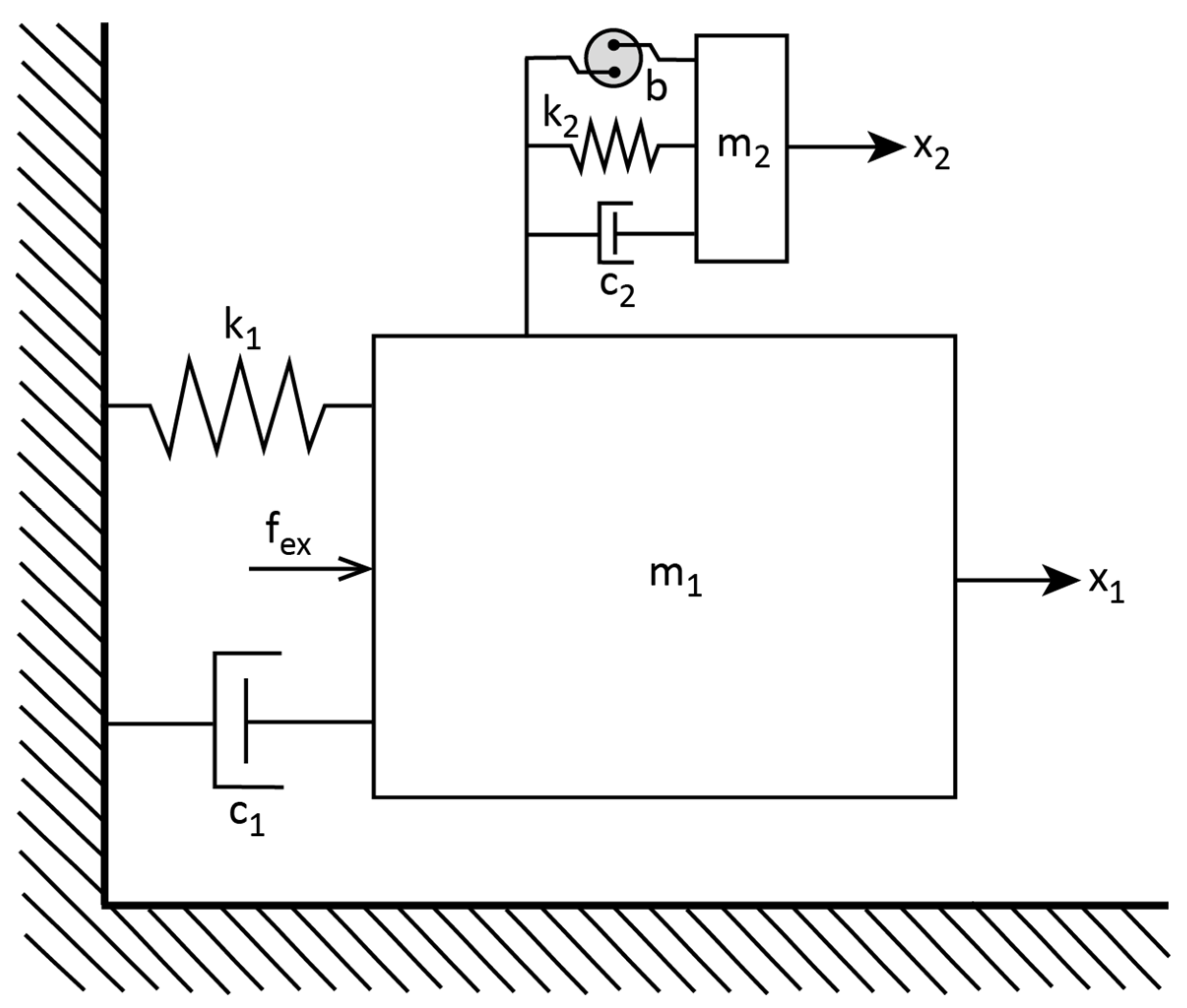
The aim of this research is to investigate the mitigation efficiency of the TMD-Inerter on the fundamental sway mode of the wind-excited tall building and compare the obtained results against those due to the conventional TMD. Therefore, the commonly adopted modeling approach is chosen where the building with the TMD-Inerter and TMD, respectively, is modeled in modal coordinates. The first bending mode is considered only as the TMD is effective in one mode only. For the modeling, it is assumed that the TMD-Inerter is located at the top of the building, i.e., at the anti-node of the first bending mode of the building (Figure 1), which is the commonly selected position in real tall building damping projects. Furthermore, it is assumed that the inerter is installed between the pendulum mass of the TMD and the top floor of the building. Considering these realistic assumptions, the equations of motion in modal coordinates are as follows:
where , and denote the modal acceleration, velocity, and displacement of the considered structural mode, is the modal mass, is the modal stiffness coefficient, is the modal viscous coefficient, describes the modal excitation force, and is the acceleration of the TMD mass that is given by the selected mass ratio . The dashpot damper and spring stiffness forces of the TMD are described by and . The term denotes the inerter force
where is the inertance with unit [kg] that is given by the selected inertance ratio .
Figure 1.
TMD-Inerter layout where the inerter is installed between the TMD mass and the modal structural mass corresponding to the situation when the inerter is grounded to the top story mass; the modal coordinate denotes the horizontal displacement of the first structural bending mode; and the modal excitation force is represented by .
2.2. Inerter Force Equation
The inerter force Equation (3) shows that the inerter produces a force that is proportional to the difference of the absolute accelerations of the modal mass and TMD mass, i.e., the relative acceleration of these two masses. However, according to Newton’s second law, the inertia force is a force that is proportional to the absolute acceleration of mass. It must, therefore, be concluded that the inerter force (3) is not an inertia force and hence cannot augment the mass of the TMD. This fact will be clearer when the characteristics of the inerter force are analyzed and explained in Section 3.
2.3. Excitation Force and Assessment Method
The excitation of tall buildings is given by wind loading, which is commonly modeled as narrow- to broadband excitation depending on the fluid/structure interaction and the surrounding buildings. The common procedure is to compute the structural vibrations adopting a simplified modal model of the building, taking into consideration the first sway modes in both principal directions and—if relevant—the first torsional mode. So, the acceleration response of tall buildings under wind loading is usually dominated by the first sway modes of both principal directions. acceleration response of such a building model and using narrow to broad band excitation is dominated by the first sway mode eigenfrequency. The resulting modal acceleration time history in one principal direction is assessed by the so-called peak acceleration, which is derived based on the root mean square value of the time history, and the peak factor that depends on the eigenfrequency of the considered mode; see ISO 10137:2007 []. Although this is the commonly adopted simulation and assessment method, it is not the appropriate method to assess the mitigation efficiency of the TMD-Inerter, as the above-described method does not assess the TMD-Inerter within the entire frequency range of the target sway mode. Therefore, the excitation force for this study is assumed as a harmonic excitation covering the entire frequency range of the first sway mode of the structural model (1), although it is clear that the wind excitation of tall buildings is not harmonic. The structural response is assessed by the modal displacement amplitude under steady state conditions, as this is the method used by Den Hartog, which makes it possible to compare the results with the well-known frequency response functions of the classical TMD []. The frequency response functions are normalized by the first sway mode eigenfrequency so that the results are valid independent of the tall building first sway mode eigenfrequency.
2.4. Classical TMD as Benchmark
As a benchmark, the primary structure with the classical TMD is simulated. When the TMD is envisaged to minimize the structural displacement, the optimal TMD stiffness coefficient and the viscous coefficient are given by the design rules according to Den Hartog []
where the TMD natural frequency and damping ratio are given as follows:
Note that the eigenfrequency of the target mode of the primary structure must be used in (5) when is derived by (7) with the cubic term.
3. Inerter Force for Harmonic Vibrations
3.1. Inerter Force Characteristics
For harmonic terminal accelerations, the inerter force (3) can be formulated as a function of terminal displacements as follows:
where is the frequency of vibration, which is equal to the excitation frequency. The term guarantees that the inerter force that is computed based on the relative displacement (8) has the same force amplitude as the inerter force that is computed based on the relative acceleration (3), and the minus sign guarantees that the inerter force (8) is in phase with the inerter force (3). So, the formulation (8) of the inerter force as a function of the relative displacement of its terminals generates the same force as the original inerter Equation (3).
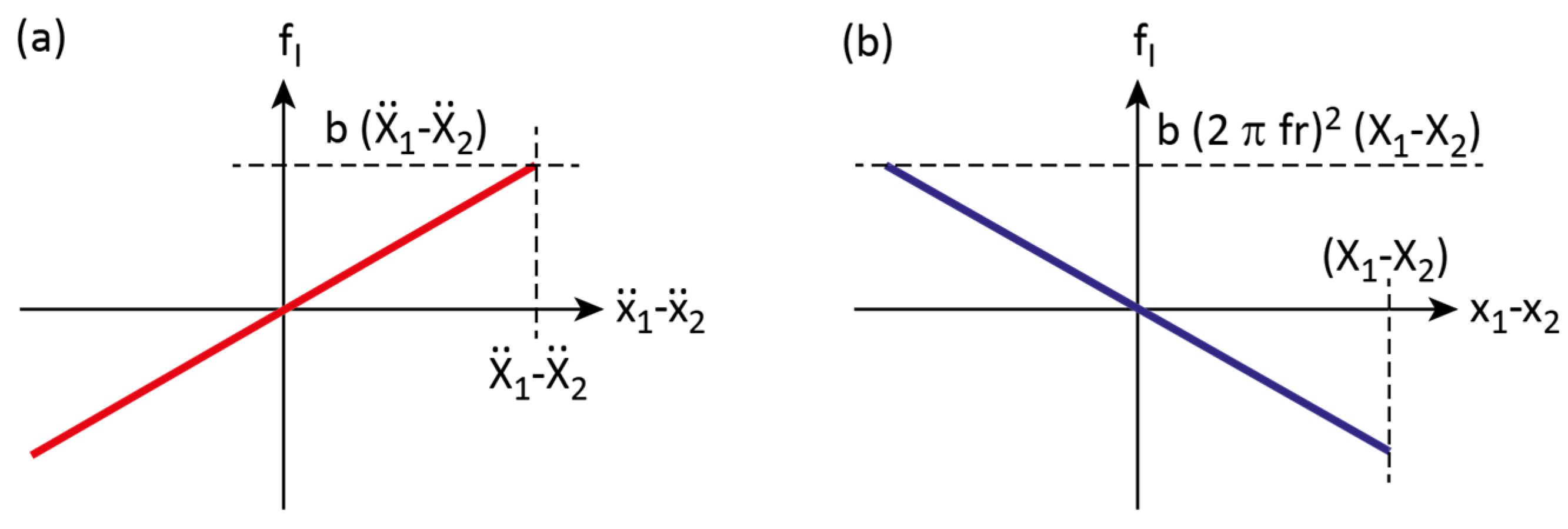
The formulation of the inerter force as a function of the difference of the terminal displacements and (8) shows that the inerter force is in fact a negative stiffness force that acts on the TMD mass (and structural mass) with the following dependent stiffness coefficient:
The associated diagrams of the inerter force versus relative acceleration and relative displacement between both terminals are depicted in Figure 2.
Figure 2.
(a) Inerter force plotted versus relative terminal acceleration and (b) plotted versus relative terminal displacement showing the negative stiffness characteristic of the inerter force.
3.2. Strategies to Compensate for Inerter Negative Stiffness
To ensure optimum frequency tuning of the TMD-Inerter, the frequency-dependent negative stiffness characteristics of the inerter need to be compensated by a frequency-dependent stiffness of the TMD-Inerter, which can be realized by a controlled actuator only; this is shown in Section 4.1. When the inerter’s negative stiffness shall be compensated by a passive spring of the TMD-Inerter, then both the TMD-Inerter stiffness and damping must be redesigned. This is discussed in Section 4.2 and Section 4.3.
4. Optimization of the TMD-Inerter
4.1. Compensation of Frequency-Dependent Negative Stiffness Force of the Inerter
As shown in Section 3, the inerter applies a negative stiffness force on the TMD mass that depends on the frequency of vibration. As a result, the natural frequency of the TMD-Inerter is far from optimal tuning. To ensure optimum frequency tuning of the TMD-Inerter, the design of the TMD-Inerter stiffness must compensate for the frequency-dependent negative stiffness (9) of the inerter. This leads to the following design rule:
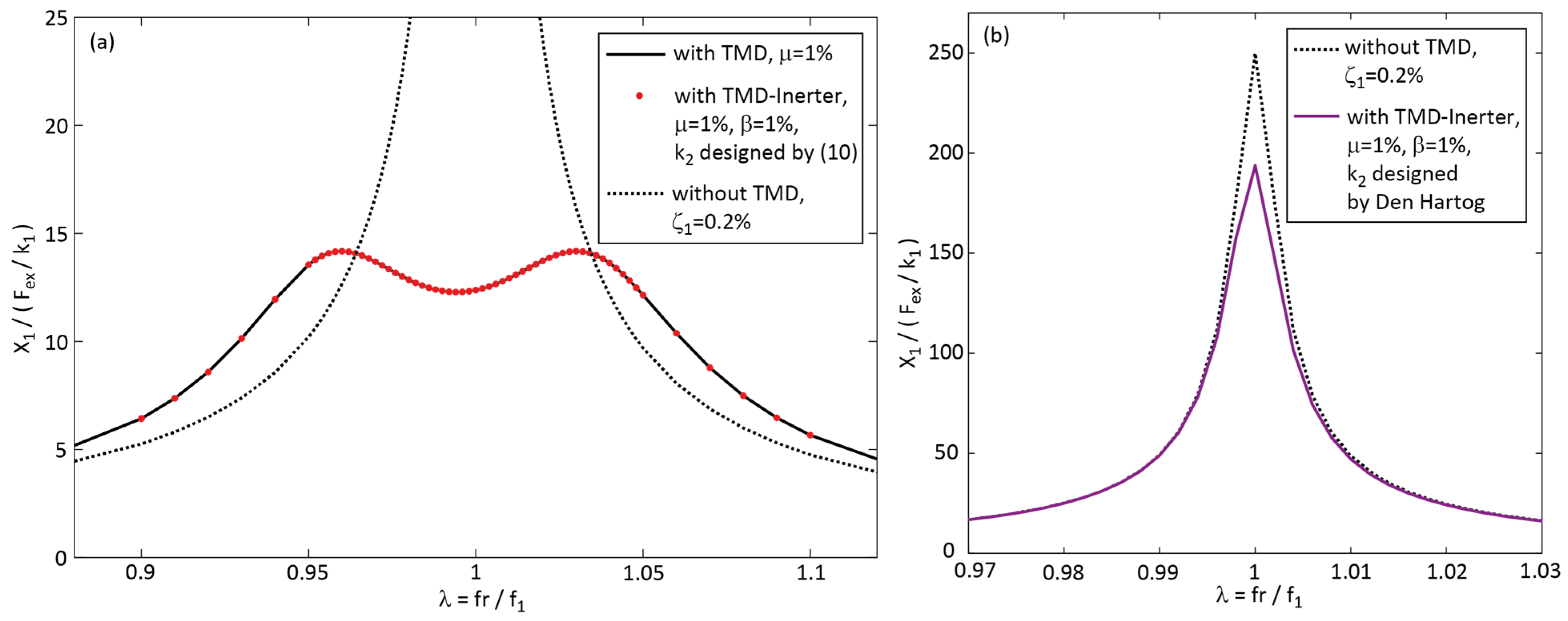
Due to the dependency of the stiffness tuning (10) on the actual frequency of vibration , the stiffness design rule (10) cannot be realized by a passive spring but would require a controlled actuator. The optimality of the stiffness design rule (10) is verified by the simulation of the equations of motion (1, 2) with , according to (10). The resulting steady-state displacement amplitude of the primary structure, which is normalized by the static displacement , is depicted in Figure 3a by the red dots; as a benchmark, the performance due to the classical TMD is plotted by the black solid line. The normalized displacement amplitudes of the primary structure without supplemental damping and with the TMD-Inerter with without negative stiffness compensation (Den Hartog design (4)) are plotted in Figure 3b. It is clearly observed that the stiffness design (10) fully compensates for the frequency-dependent negative stiffness of the inerter, whereby the optimum performance due to the classical TMD is achieved. In contrast, when the TMD-Inerter stiffness is designed according to Den Hartog’s rule (4), the resulting performance is close to that of the primary structure without supplemental damping because this stiffness design (4) does not compensate for the frequency-dependent negative stiffness of the inerter (Figure 3b). For the depicted example with , the resulting TMD-Inerter shows a natural frequency of 0 Hz because the negative stiffness of the inerter force compensates for the passive spring stiffness of the TMD. Therefore, the mass of the TMD-Inerter acts only as an additional mass on the structure but not as an additional degree of freedom.
Figure 3.
(a) Normalized primary structure displacement amplitude due to the TMD-Inerter with stiffness design according to (10) and due to the classical TMD; (b) normalized primary structure displacement amplitudes of the structure without supplemental damping and with the TMD-Inerter with stiffness according to Den Hartog’s design.
4.2. Compensation of Inerter Negative Stiffness by a Passive Spring
To be able to realize the TMD-Inerter stiffness by a passive spring, the TMD-Inerter stiffness must be designed such that it fully compensates for the frequency-dependent negative stiffness of the inerter at one selected frequency of vibration. As a first try, it is reasonable to select either or as frequencies at which the full inerter negative stiffness compensations are achieved. This leads to the following two design rules:
The design rule (12) is published in many papers but with the wrong explanation that the inertance would increase the TMD mass. The correct explanation is that the inerter exerts the negative stiffness coefficient , see Equation (8), which needs to be compensated as far as possible by the consideration of the term or in the designs (11) and (12) of the passive spring stiffness.
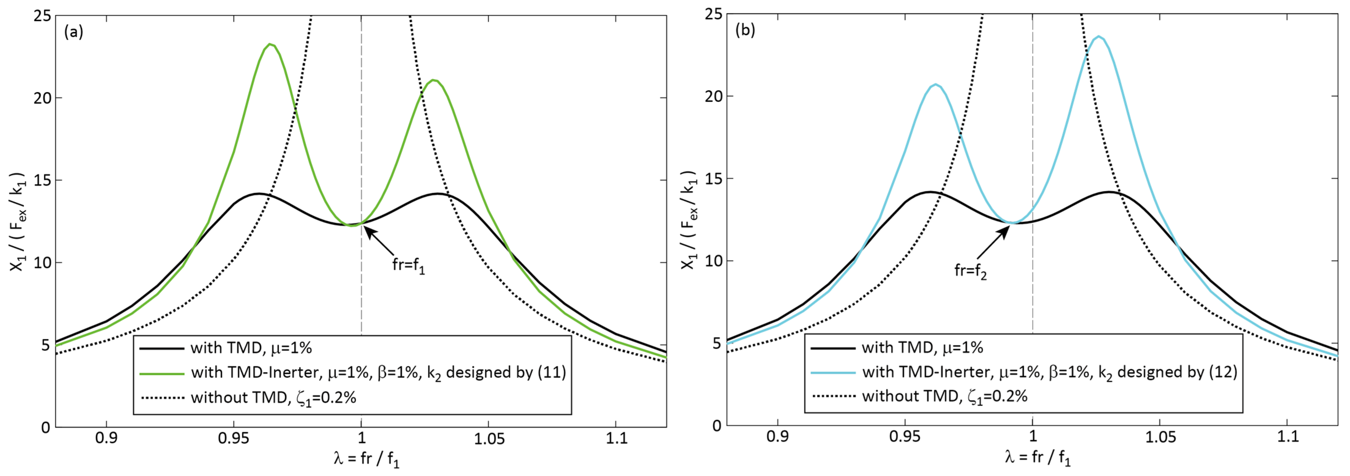
The normalized structural displacement amplitudes resulting from the two tunings (11) and (12) are depicted in Figure 4a,b. The green line is obtained from the stiffness design (11), which fully compensates for the inerter negative stiffness at the vibration frequency , while the stiffness design (12) achieves the full compensation at (cyan line). At all other frequencies of vibration, both stiffness designs (11) and (12) do not fully compensate for the frequency-dependent inerter negative stiffness, which is the only reason for the significantly higher displacement responses in these regions. Although these higher peaks look similar to those of an underdamped TMD-Inerter, it is underlined that these higher peaks to the left and right of and , respectively, are only caused by the fact that the inerter negative stiffness compensation terms of (11) and (12) are formulated based on the constant frequencies and , respectively, to be able to realize by a passive spring. Therefore, the passive spring stiffness designs (11) and (12) fully compensate for the inerter negative stiffness only at and , respectively, while at all other frequencies of vibration the inerter negative stiffness is not fully compensated by (11) and (12).
Figure 4.
Normalized primary structure displacement amplitude due to the TMD-Inerter with (a) stiffness design according to (11) and (b) stiffness design according to (12) compared to the performances of the primary structure with classical TMD and without supplemental damping.
To avoid the uneven peaks of the displacement responses due to the stiffness designs (11) and (12), it is obvious to design the stiffness such that the negative stiffness of the inerter is fully compensated at the average of the frequencies and
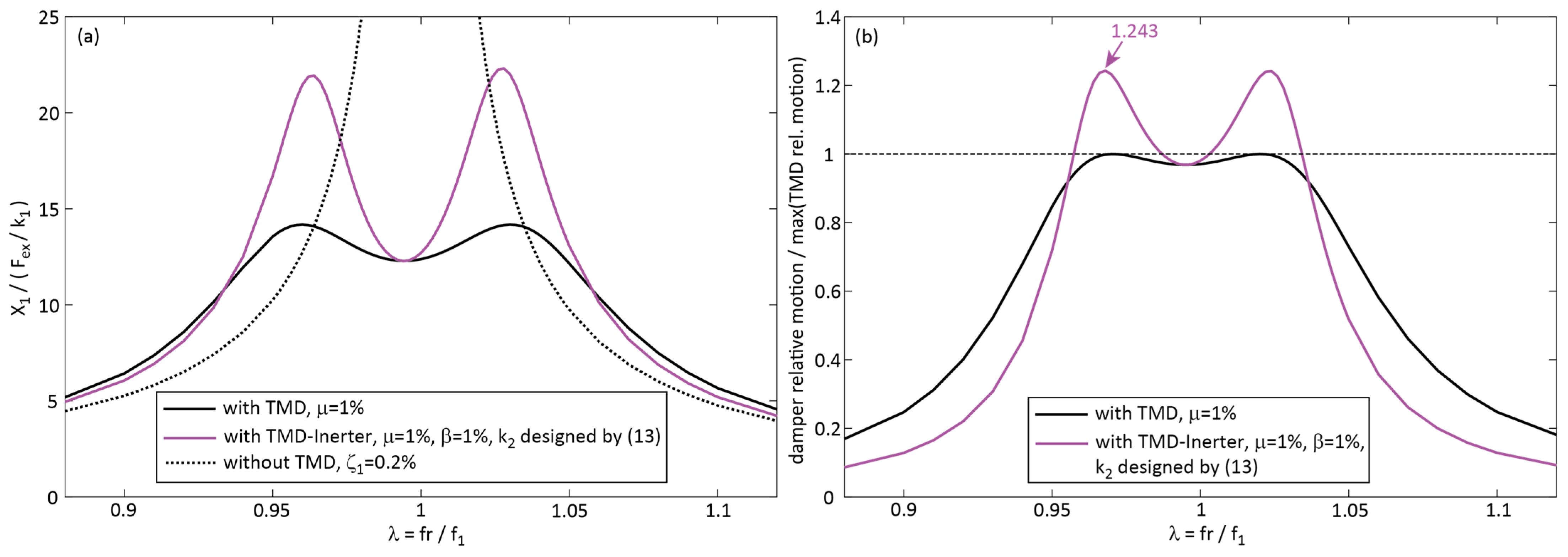
This stiffness design leads to a displacement response with approximately equal peaks, as shown by the magenta line in Figure 5a. For this frequency tuning, the relative motion of the TMD-Inerter is plotted in Figure 5b as well. For better comparison with the TMD solution, the damper relative motion is normalized by the maximum of the TMD solution. Figure 5a,b show that the stiffness design (13) leads to greater primary structure displacement and greater damper relative motion than the classical TMD solution. Hence, the stiffness design (13) must be enriched with augmented damping, which is discussed next (Section 4.3).
Figure 5.
(a) Normalized primary structure displacement amplitude and (b) normalized damper relative motion due to the TMD-Inerter with stiffness design according to (13) compared to the performances of the primary structure with classical TMD and without supplemental damping.
4.3. Passive Inerter Stiffness Compensation Combined with Numerically Optimized Damping
The stiffness design rule (13) can be realized by a passive spring and leads to approximately equal peaks of the structural displacement (Figure 5a). Hence, the stiffness tuning is close to optimal. However, the peaks are significantly higher than those of the classical TMD (Figure 5a). It is, therefore, reasonable to combine the stiffness design rule (13) with the approach of increased damping of the TMD-Inerter. On the one hand, this will reduce the two peaks to the left and right of ; on the other hand, it will increase the minimum in the vicinity of . The increased damping design is formulated as follows:
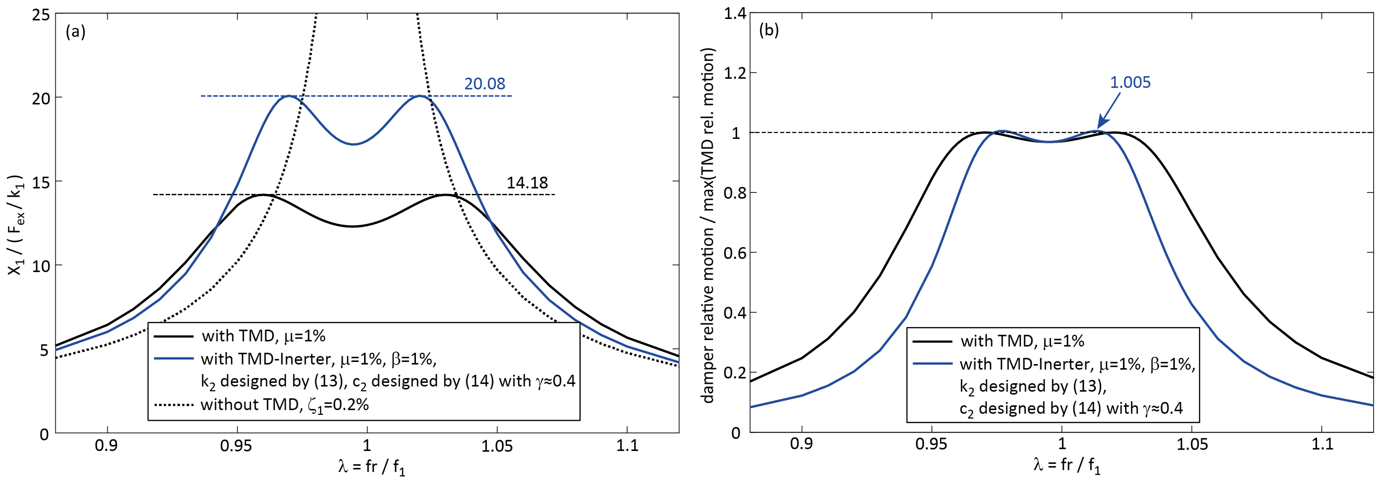
where the damping ratio is designed according to the classical Formula (7), and the increased damping is defined by the damping increase factor that scales the inertance . The damping increase factor is numerically optimized for minimum structural displacement response within the entire frequency range. For the example under consideration (), the optimized value of turns out to be approximately 0.4. For and, therefore, this means that the optimized TMD-Inerter is designed with approximately 140% damping coefficient compared to the classical TMD. The associated normalized displacement response is plotted in Figure 6a by the blue solid line. Despite the optimized damping, the structural displacement response is approximately 41.6% greater than that of the classical TMD. This is because the stiffness design (13) is aimed to be realizable by a passive spring and, therefore, (13) can fully compensate for the frequency-dependent negative stiffness of the inerter at one frequency only, in this case at ; at all other frequencies of vibration the inerter negative stiffness is not fully compensated. The maximum damper relative motion of this TMD-Inerter solution is almost the same as that of the classical TMD (Figure 6b).
Figure 6.
(a) Normalized primary structure displacement amplitude and (b) normalized damper relative motion due to the TMD-Inerter with stiffness design according to (13) and numerically optimized damping compared to the performances of the primary structure with classical TMD and without supplemental damping.
5. Summary and Conclusions
This article analyzes the physics, tuning, and performance of the TMD-Inerter that is installed at the anti-node of the primary structure. The realistic configuration is considered where the inerter is grounded to the primary structure next to the TMD. For harmonic vibrations, the inerter force is formulated as a function of the displacements of both inerter terminals. This formulation demonstrates that the inerter force in fact exerts a negative stiffness force with a frequency-dependent negative stiffness coefficient. This frequency-dependent negative stiffness coefficient can only be fully compensated by a real-time controlled spring of the TMD-Inerter. Then, the exact same performance as the classical TMD is achieved, proving that the inerter force produces a frequency-dependent negative stiffness force. When the stiffness of the TMD-Inerter is realized by a passive spring, full compensation of the inerter negative stiffness within the entire frequency range is not possible. For this case, the close to optimal stiffness tuning of the TMD-Inerter is obtained when it is designed based on the average of the eigenfrequency of the primary structure and the natural frequency of the TMD. This close to optimal stiffness tuning is combined with numerically optimized augmented damping of the TMD-Inerter. Despite the close to optimal stiffness tuning and numerically optimized damping, this approach results in approximately 41.6% greater primary structure displacement response than the classical TMD solution. The reason for this shortcoming is that a passive TMD-Inerter spring cannot fully compensate for the frequency-dependent negative stiffness of the inerter within the entire frequency range.
The expectation of the inerter in combination with the TMD was that the inerter could virtually increase the TMD mass and thereby improve the damping of the primary structure without adding physical mass to the TMD mass. However, this is physically not correct because the inerter force is—by definition—in proportion to the relative acceleration of both terminals, but—according to Newton’s second law—the inertia force is in proportion to the absolute acceleration of the mass. This means that only a device that exerts a force in proportion to the absolute acceleration of the TMD mass could virtually increase the TMD mass.
Funding
This research received no external funding.
Data Availability Statement
All simulation data are available upon request.
Acknowledgments
The author gratefully acknowledges the support of Maurer SE, Munich, Germany, Maurer Engineering GmbH, Munich, Germany, and Maurer Switzerland GmbH, Pfaffhausen, Switzerland.
Conflicts of Interest
Dr. Felix Weber is an employee of Maurer Switzerland GmbH.
References
- Den Hartog, J.P. Mechanical Vibrations, 4th ed.; McGraw-Hill: New York, NY, USA, 1956. [Google Scholar]
- Zucca, M.; Longarini, N.; Simoncelli, M.; Aly, A.M. Tuned Mass Damper Design for Slender Masonry Structures: A Framework for Linear and Nonlinear Analysis. Appl. Sci. 2021, 11, 3425. [Google Scholar] [CrossRef]
- ISO 10137; Bases for Design of Structures—Serviceability of Buildings and Walkways against Vibrations. International Organization for Standardization, ISO Central Secretariat, Chemin de Blandonnet 8, CP 401-1214 Vernier: Geneva, Switzerland, 2007.
- Smith, M.C. The Inerter: A Retrospective. Annu. Rev. Control Robot. Auton. Syst. 2020, 3, 361–391. [Google Scholar] [CrossRef]
- Giaralis, A.; Petrini, F. Wind-induced vibration mitigation in tall buildings using the tuned mass-damper-inerter. J. Struct. Eng. 2017, 143. [Google Scholar] [CrossRef]
- Pietrosanti, D.; De Angelis, M.; Basili, M. Optimal design and performance evaluation of systems with Tuned Mass Damper Inerter (TMDI). Earthq. Eng. Struct. Dyn. 2017, 46, 1367–1388. [Google Scholar] [CrossRef]
- Weber, F. TMD-Inerter for Tall Building Damping: Approximate Closed-Form Solution, Performance and Conclusions. Buildings 2025, 15, 1829. [Google Scholar] [CrossRef]
- Dai, J.; Xu, Z.D.; Gai, P.P. Tuned mass-damper-inerter control of wind-induced vibration of flexible structures based on inerter location. Eng. Struct. 2019, 199, 109585. [Google Scholar] [CrossRef]
- Petrini, F.; Giaralis, A.; Wang, Z. Optimal tuned mass-damper-inerter (TMDI) design in wind-excited tall buildings for occupants’ comfort serviceability performance and energy harvesting. Eng. Struct. 2020, 204, 109904. [Google Scholar] [CrossRef]
- Wang, Q.; Qiao, H.; Li, W.; You, Y.; Fan, Z.; Tiwari, N. Parametric optimization of an inerter-based vibration absorber for wind induced vibration mitigation of a tall building. Wind Struct. 2020, 31, 241–253. [Google Scholar]
- Weber, F.; Huber, P.; Borchsenius, F.; Braun, C. Performance of TMDI for Tall Building Damping. Actuators 2020, 9, 139. [Google Scholar] [CrossRef]
- Zhang, Z.; Chen, B.; Hua, X. Closed-form optimization of tuned mass-damper-inerter (TMDI) in flexible structures. J. Build. Eng. 2023, 72, 106554. [Google Scholar] [CrossRef]
- Barredo, E.; Larios, M.; Mayén, J.; Flores-Hernández, A.A.; Colín, J.; Arias-Montiel, M. Optimal design for high-performance passive dynamic vibration absorbers under random excitation. Eng. Struct. 2019, 195, 469–489. [Google Scholar] [CrossRef]
- Barredo, E.; Larios, M.; Colín, J.; Mayén, J.; Flores-Hernández, A.A.; Arias-Montiel, M. A novel high-performance passive non-traditional inerter-based dynamic vibration absorber. J. Sound Vib. 2020, 485, 115583. [Google Scholar] [CrossRef]
- Alotta, G.; Failla, G. Improved inerter-based vibration absorbers. Int. J. Mech. Sci. 2021, 192, 106087. [Google Scholar] [CrossRef]
- Weber, F.; Borchsenius, F.; Distl, J.; Braun, C. Performance of numerically optimized Tuned Mass Damper with Inerter (TMDI). Appl. Sci. 2022, 12, 6204. [Google Scholar] [CrossRef]
- Konar, T.; Ghosh, A. Tuned mass damper inerter for seismic control of multi-story buildings: Ten years since inception. Structures 2024, 63, 106459. [Google Scholar] [CrossRef]
Disclaimer/Publisher’s Note: The statements, opinions and data contained in all publications are solely those of the individual author(s) and contributor(s) and not of MDPI and/or the editor(s). MDPI and/or the editor(s) disclaim responsibility for any injury to people or property resulting from any ideas, methods, instructions or products referred to in the content. |
© 2025 by the author. Licensee MDPI, Basel, Switzerland. This article is an open access article distributed under the terms and conditions of the Creative Commons Attribution (CC BY) license (https://creativecommons.org/licenses/by/4.0/).