Abstract
Simultaneous Localization and Mapping (SLAM) is essential for autonomous movement in intelligent robotic systems. Traditional SLAM using a single sensor, such as an Inertial Measurement Unit (IMU), faces challenges including noise and drift. This paper introduces a novel Cartographer-based SLAM approach for DAMR trajectory generation in indoor environments to reduce drift errors and improve localization accuracy. This SLAM approach integrates multi-sensor data with extended Kalman filter (EKF) fusion from wheel odometry, an RGB-D camera (RTAB-Map), and an IMU for precise mapping with DAMR trajectory generation and is compared with the heading reference trajectory generated by robot pose estimation and frame transformation. This system is implemented in the Robot Operating System (ROS 2) for coordinated data acquisition, processing, and visualization. After experimental verification, the DAMR trajectories generated are closer to the reference trajectory and drift errors are tuned. The experimental results revealed that the DAMR trajectory with multi-sensor data integration using the EKF effectively improved the positioning accuracy and robustness of the system. The proposed approach shows improved alignment with the reference trajectory, yielding a mean displacement error of 0.352% and an absolute trajectory error of 0.007 m, highlighting the effectiveness of the fusion approach for accurate indoor robot navigation.
1. Introduction
SLAM is crucial for autonomous robots, enabling them to understand and navigate their surroundings by estimating their position and simultaneously constructing a map [1,2,3,4]. This state estimation technique utilizes sensor data, with key methods including particle filters, Kalman filters, and graph-based optimization [5], which are particularly effective for indoor mapping. SLAM systems are categorized into laser-based, vision-based, and multi-sensor fusion systems, utilizing various algorithms and sensors, such as LiDAR, cameras, IMUs, and odometry, for accurate motion estimation and environmental mapping [6]. A thorough examination of different SLAM algorithms, their associated challenges, and recent advancements in the field was conducted, and the issues surrounding the implementation of SLAM in construction environments are discussed [7]. LiDAR sensors enable SLAM to gather information about its environment for real-time mapping and localization [8]. One study addresses the implications of SLAM in mobile robots and provides a detailed examination of popular SLAM methods developed over the past decade, concluding that both G-mapping and Cartographer provide important SLAM features as well as loop closure detection [9]. Experiments in both replicated and real-world settings have illustrated the benefits and drawbacks of the SLAM approaches covered here for dynamic and complex situations [10].
In this study, Cartographer SLAM is used for generating a map for autonomous navigation in indoor environments. Cartographer is an open-source SLAM library developed by Google, enabling real-time map building and positioning for robots and mobile devices [11]. It integrates with ROS and operates using various sensors, such as LiDAR, IMUs, and cameras, to gather environmental data [12,13]. Cartographer utilizes SLAM algorithms to create high-quality maps and ensure accurate localization in unknown environments [14,15]. It features two main subsystems: local SLAM, which generates locally consistent sub-maps while managing drift, and global SLAM, which identifies loop closures and integrates sensor data for a cohesive global map. Local SLAM calculates the robot’s trajectory using odometer and IMU data, updates the pose with LiDAR data and creates sub-maps. Global SLAM focuses on loop detection and optimization to unify all sub-maps into a comprehensive map [16]. SLAM Cartographer and SLAM Toolbox were used in dynamic environments, finding that Cartographer outperforms Toolbox, providing insights for enhancing AGV performance [17]. Recent advancements in SLAM techniques have focused on improving performance in dynamic environments [18,19]. Real-time 3D mapping capabilities for robots in challenging conditions through advanced sensors and algorithms are demonstrated [20]. The effectiveness of omnidirectional cameras is a viable alternative to stereo cameras in SLAM applications [21]. The limitations of traditional SLAM in dynamic settings can be minimized by proposing an adaptive dynamic object segmentation method that reduces computational overhead while maintaining tracking accuracy [22]. Feature-based SLAM algorithms, such as ORB-SLAM3 and RTAB-Map, offer real-time performance in various environments, while laser-based SLAM outperforms grid and feature-based methods in uneven outdoor terrains [23,24].
The literature reveals a research gap regarding the difficulties of single-sensor SLAM systems in mapping and localization for mobile robots. Recent studies on mobile robot mapping and navigation highlight the effectiveness of multi-sensor fusion techniques combining visual and LiDAR sensors using the RTAB-Map method, which significantly outperform individual sensors [25]. A localization system integrating AMCL and RTAB-Map found that RTAB-Map generally offers better positioning accuracy, although AMCL excels in poor lighting conditions [26]. The combination of LiDAR and a visual camera creates map generation for mobile robot navigation [27]. A comparison of LiDAR SLAM and Visual SLAM noted that LiDAR is preferable for outdoor environments, while Visual SLAM is more effective in indoors [28,29]. However, there are some limitations in sensor combinations of mobile robots to navigate in indoor environments. Sensor fusion combines data from multiple sensors, such as wheel encoders, IMUs, and cameras, to improve the accuracy of a robot’s state estimation while overcoming individual sensor limitations like drift and noise [30]. The extended Kalman filter plays a crucial role in this process by leveraging the strengths of various sensors to enhance position and orientation consistency as well as fault tolerance [31,32,33,34,35]. While multi-sensor SLAM offers potential accuracy improvements, further development of fusion strategies among LiDAR, wheel odometry, IMUs, and RGB-D cameras is essential [36,37]. Traditional methods in Visual SLAM also face challenges in loop detection and position accuracy within multi-sensor contexts, prompting a need for more effective approaches [38,39].
From the literature study, the research gaps identified in existing sensor frameworks suggest that mobile robots are facing challenges in fusion accuracy for determining pose estimation and trajectory generation during navigation in indoor environments. To address these gaps, a novel methodology is introduced to generate DAMR trajectories by integrating them with the sensor framework. Although odometry, IMU-based navigation, Visual SLAM, and multi-sensor fusion techniques are well established in robotics research, the novelty of this work lies in the structured integration framework, reference trajectory formulation, and systematic experimental validation developed for the DAMR within a unified ROS2–Cartographer architecture. This study presents a coherent methodological framework that enables controlled comparative evaluation of individual sensors and multi-sensor fusion with an EKF framework under identical operating conditions.
A key contribution is the formulation of a heading-constrained reference trajectory derived from transform frame (TF)-based map-to-base transformations generated by Cartographer SLAM. This approach provides a consistent internal performance baseline without relying on external motion capture systems and enables fair comparison across different localization strategies. Furthermore, the work integrates LiDAR-based SLAM, RGB-D visual odometry (RTAB-Map), wheel encoder-based odometry, and IMU orientation data implemented via micro-ROS within an extended Kalman filter architecture specifically adapted to the DAMR. The structured evaluation includes comparison of individual sensors and multi-sensor fusion using both displacement error and absolute trajectory error metrics. Experimental validation is conducted on a real fabricated DAMR platform in an indoor laboratory environment, demonstrating measurable reduction in drift and improved trajectory stability. The proposed framework assesses localization performance with trajectory evaluation metrics against reference trajectories and showcases enhanced accuracy through the integration of multi-sensor fusion with EKF.
2. Methodology
In this section, a novel methodology is introduced to determine the trajectory generation of the DAMR using multi-sensor data. The designed multi-sensor framework for trajectory generation is clearly explained in the following subsections. First, the DAMR pose information is derived from the transformation between the map and base_link frames in the TF tree, constantly updated by the SLAM back-end, utilizing scan matching and global pose graph optimization to ensure spatial consistency along the trajectory. The simulated trajectory obtained by the position and orientation of the DAMR is taken as a reference trajectory.
The DAMR will be tested in a real environment with the designed algorithmic framework of individual sensors like IMUs, wheel odometry, RGB-D camera odometry with RTAB-Map and multi-sensor fusion with EKF in three combinations: the integration of wheel odometry and an IMU with EKF; RTAB-Map odometry and an IMU with EKF; and RTAB-Map odometry, wheel odometry and an IMU with EKF (proposed approach). The trajectories generated after testing will be compared and validated with the reference trajectory. The overall framework is implemented within ROS 2 for coordinated data acquisition, processing, and visualization.
2.1. Cartographer SLAM
Cartographer is an open-source system designed for real-time SLAM in 2D and 3D environments, is compatible with various platforms and sensors, and features a ROS wrapper. It enhances pose estimation by addressing error accumulation through the matching of laser scans to sub-maps at estimated positions, thereby facilitating the identification of loop closures. The transformation of scan points (1) into a probability grid sub-map using the Ceres scan matcher enables hits and misses to be calculated based on the insertion of new scans [40].
Ceres scan matching (2) is utilized to optimize probabilities for accurate scan poses within the sub-map. Tξ converts hk from the scan frame to the sub-map frame based on the scan pose, while Msmooth is defined as a smooth version of the probability values within the local sub-map.
Mathematical optimization of smooth functions often yields better precision than grid resolution, necessitating reasonable initial estimates for local optimization. An IMU can measure angular velocities to estimate the rotational component θ of the pose between scan matches.
As demonstrated by the Cartographer architecture, as shown in Figure 1, the DAMR uses a layered approach for mapping and localization. To guarantee appropriate message handling and frame alignment, LiDAR sensor data is first collected and processed. The local SLAM front-end performs initial pose estimation and scan matching to generate local trajectory data. Sub-maps are gradually created to depict the surrounding environment based on this data.
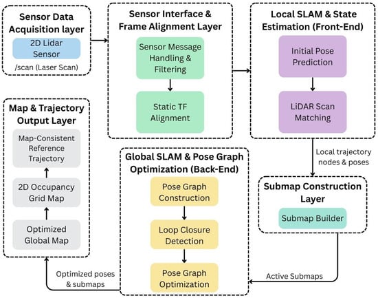
Figure 1.
Cartographer SLAM framework for DAMR trajectory estimation.
After that, the global SLAM back-end creates a pose graph, finds loop closures, and optimizes the map to make it more consistent. Accurate navigation in indoor environments is made possible by the final output, which includes a consistent robot trajectory and an optimized global map.
2.2. Wheel Odometry
Wheel odometry is a widely used method for estimating a mobile robot’s position and orientation, known for its simplicity and cost-effectiveness. This technique measures wheel rotation with encoders and utilizes kinematic equations to calculate the robot’s displacement and heading over time. The mobile platform with wheel configuration is detailed in Figure 2. Omnidirectional motion is achieved by using four Mecanum wheels positioned at the corners of a square base. Despite the complexity of the mechanical design due to angled rollers, this configuration allows for smoother contact surfaces, enabling the support of higher loads.
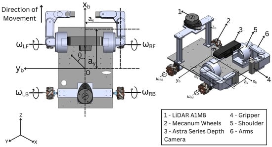
Figure 2.
Two-dimensional and 3D representation of the DAMR kinematic mobile base.
The velocities in the mobile base frame (, , ) are a function of the four-wheel velocities (, , ) obtained from the standard derivation of forward and inverse kinematics of the four-wheeled omnidirectional platform [41], as shown in (3) and (4):
where
- —the radius of the wheels;
- —half of the distance between the front wheels;
- —half of the distance between the front wheel and the rear wheels;
- —angular velocity of the left front wheel;
- —angular velocity of the left back wheel;
- —angular velocity of the right front wheel;
- —angular velocity of the right back wheel.
The wheel velocities of the mobile platform [41] can be obtained from (3) as follows:
Due to their 45° roller configuration, Mecanum wheels provide the robot with omnidirectional mobility, with an inverse kinematic model that maps wheel angular velocities (5) to velocities in the robot frame, as shown in (6)–(8).
Longitudinal Velocity:
Transversal Velocity:
Angular Velocity:
A motion model for the DAMR is derived that is suitable for pose estimation, as shown in Figure 3. The motion model is based on odometry measurements obtained from wheel encoders [42]. Odometry can be treated as a control because most vehicle control systems regulate the vehicle’s movements within a closed position control loop based on odometry. In this case, the command values of the control loop correspond directly to odometry. This section outlines the deterministic wheel odometry formulation applied on an ESP32 microcontroller for a four-wheeled Mecanum mobile robot. It details how the model estimates the robot’s planar pose using incremental encoder measurements and Mecanum inverse kinematics, publishing the odometry as a ROS 2 nav_msgs/odometry message via micro-ROS.

Figure 3.
Movement of the DAMR to estimate odometry poses.
The wheel angular velocities of the four wheels are determined by converting encoder pulses from the wheel encoders:
where
- PPR is pulse per revolution and are the encoder sign conventions.
The wheel odometry architecture illustrates how encoder feedback from the drive system is used to estimate the robot’s local motion, as shown in Figure 4. DC motor encoders produce pulse signals during wheel rotation at the actuation and sensing layer, where the process starts. The encoder interface layer uses quadrature encoder interrupt processing to handle these signals. Pulse differences over a predetermined time window are then calculated and converted into angular velocity values to estimate wheel speed. The Mecanum kinematics layer receives the estimated wheel velocities from Equations (9)–(12) and uses forward kinematics to calculate the robot’s motion. A local wheel odometry estimate is created by integrating the resultant pose over time into the odometry integration layer.
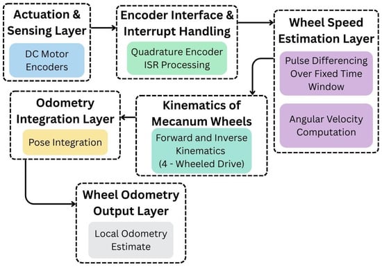
Figure 4.
Wheel odometry framework for DAMR trajectory estimation.
2.3. IMU Framework
The IMU architecture shown in Figure 5 illustrates how inertial sensing and orientation estimation are handled by the IMU data processing architecture, which includes an I2C interface, an accelerometer, a gyroscope, and a magnetometer, all of which supply raw sensor data. Scaling and processing are used to extract this data and transform it into proper physical values. Roll, pitch, and yaw are used to calculate orientation before being converted into a quaternion representation. ROS 2 IMU messages contain processed data, which is then published via an IMU publisher node. For higher-level tasks, such as localization and navigation, this flow ensures accurate orientation and motion data.
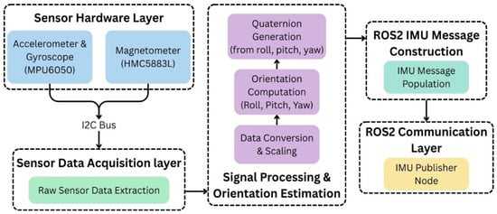
Figure 5.
IMU framework for DAMR trajectory estimation.
2.4. RGB-D Camera Odometry
Visual odometry estimates a robot’s motion by analysing sequential images from onboard cameras, tracking visual features to infer changes in position and orientation. This technique is particularly beneficial in environments where reliable GPS is unavailable. It involves detecting and matching features, such as corners and edges, and calculating the relative pose through geometric transformations. In visual odometry, depth information enhances accuracy by triangulating matched features from synchronized images. For the DAMR robot, the RGB-D camera captures image sequences to estimate motion. Challenges for camera odometry include dynamic lighting, lack of texture, occlusion, motion blur, scale ambiguity in monocular setups, and drift over time without global corrections.
The RGB-D odometry architecture, as illustrated in Figure 6, demonstrates how it utilizes both depth and visual information to estimate the robot’s motion. Acquiring RGB image streams, depth image streams, and camera calibration data is the first step in the process. RGB and depth data are aligned and pre-processed after these inputs are sent to the synchronization and pre-processing stage. Visual feature extraction and inter-frame feature matching are then performed using synchronized data. With the help of depth-assisted motion estimation, the RGB-D motion estimation stage utilizes this data to perform incremental pose estimation. The odometry output layer publishes the resulting visual odometry estimates, which are then utilized for mapping and navigation.
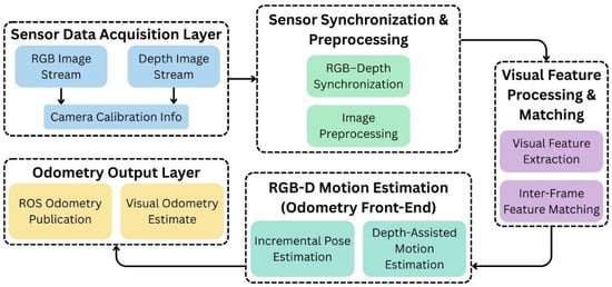
Figure 6.
RGB-D camera odometry framework for DAMR trajectory estimation.
2.5. Multi-Sensor Fusion with EKF
Sensor fusion addresses the limitations of individual sensors by integrating data from multiple sources, thereby enhancing strengths and mitigating weaknesses. A key technique mentioned is the EKF, which is a recursive estimator that optimally estimates the system’s state by minimizing uncertainty. To achieve reliable localization in real-world environments, estimating a robot’s pose using noisy sensor data is crucial. The main challenge is predicting the robot’s new state, incorporating uncertainty from measurements and motion. EKF is well-suited for this purpose, enabling recursive state estimation despite the nonlinear dynamics typical in robotics.
In this paper, an EKF is implemented to fuse sensor data from the wheel odometry, RTAB-Map odometry and IMU. EKF establishes a probabilistic framework for pose estimation, accounting for sensor data uncertainty. The EKF operates through two primary phases: prediction and update. The prediction phase is based on the motion model derived from wheel encoders, estimating pose through displacement and heading inferred from these measurements. In prediction steps (13) and (14), the EKF estimates the next state using the previous state and control inputs while propagating uncertainty through the motion model. Update phases (15)–(18) use IMU orientation to correct predictions, allowing continuous pose estimation by combining the low-drift position from encoders with reliable short-term orientation updates from the IMU. The EKF specifically employs the encoder-based motion model for prediction and IMU yaw for corrections. Upon receiving a new sensor measurement, such as acceleration or angular velocity from the IMU, the EKF corrects the predicted state, thereby enhancing accuracy and reducing uncertainty.
- Prediction Step:
The prediction step estimates the prior state mean and covariance using the motion model:
- Jacobian of the Motion Model:
- Measurement Update Steps:
These update steps correct the predicted estimate using sensor measurements:
where
- xt—State vector at time step t
- —Estimated state vector at time step t (a posterior estimate)
- —Predicted state estimate at time step t given measurements up to time t − 1 (a priori estimate)
- ut—Control input vector at time step t
- xt, yt—Robot position coordinates in the global frame
- θt—Robot heading (yaw angle)
- vt—Linear velocity
- ωt—Angular velocity
- Δt—Sampling time interval
- zt—Measurement vector at time step t
- yt—Innovation (measurement residual)
- Pt—State estimation error covariance matrix at time step t
- Pt|t−1—Predicted error covariance matrix
- Ft—Jacobian of the state transition function with respect to the state (∂f/∂x)
- Ht—Jacobian of the measurement function with respect to the state (∂h/∂x)
- Qt—Process noise covariance matrix
- Rt—Measurement noise covariance matrix
- St—Innovation covariance matrix
- Kt—Kalman gain matrix
The proposed architecture combines data from multiple sensors to produce a stable and reliable odometry estimate, as shown in Figure 7. The process begins at the sensor hardware layer, which includes wheel encoders, an IMU module, and an RGB-D camera. Data from these sensors is passed through the sensor interface and pre-processing layer, where basic handling is performed before fusion. Relevant measurements from the wheel encoders, IMU, and absolute orientation are then selected and assigned appropriate importance in the measurement selection and weighting layer. The EKF prediction block estimates the current state based on previous information, while the EKF correction layer updates this estimate using incoming measurements. The EKF fusion core combines prediction and correction to generate a filtered odometry output, which is used for reliable estimation of robot motion.
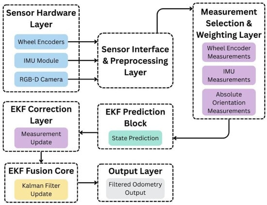
Figure 7.
Multi-sensor SLAM framework with EKF.
3. Simulation and Experimental Testing
This paper evaluates various odometry and sensor data integration methods for DAMR trajectory generation, comparing strategies that integrate wheel odometry, an IMU, and RGB-D camera odometry to overcome sensor limitations. The study employs empirical testing and error analysis in realistic indoor conditions, addressing different test paths with various challenges. Multi-sensor frameworks are evaluated, with a focus on computational efficiency for implementation on resource-constrained platforms, such as the Jetson Orin NX.
3.1. DAMR System Architecture
The DAMR is powered by the NVIDIA Jetson Orin NX, a sophisticated Edge AI computing platform that supports a ROS 2-based software stack. This architecture facilitates real-time sensor fusion, decision-making, and communication among distributed systems, enabling the robot to understand its environment and navigate effectively.
It features an Astra RGB-D camera for colour and depth data, a LiDAR A1M8 for 360-degree mapping, and an integrated IMU with gyroscope, accelerometer, and magnetometer for accurate odometry. This diverse sensor suite enables the DAMR to track its pose reliably and accurately determine its heading in complex environments. The DAMR system features a modular architecture, as shown in Figure 8, where each component has a specific function that contributes to perception, localization, navigation, and manipulation.
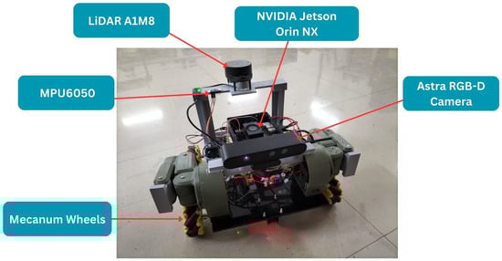
Figure 8.
DAMR fabricated model operated in an indoor laboratory.
This design enhances resilience, simplifies maintenance, and allows for future scalability. As illustrated in the hardware architecture shown in Figure 9, DAMR is designed to support motor control, computation, sensing, and stable power distribution. Through a switch and voltage regulators, a Li-Po battery provides power, ensuring that various components have the appropriate voltage levels. While encoder data is fed back for motion tracking, the motor drivers manage the four DC motors to enable the robot’s motion. As the low-level controller, an ESP32 manages encoder data, motor commands, and wireless communication with the Jetson Orin NX. The primary processing unit is the Jetson Orin NX, which communicates directly with the RGB-D camera, LiDAR, and IMU sensors. This configuration guarantees effective coordination of computation, control, and sensing.
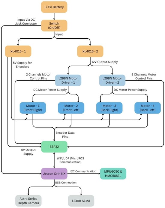
Figure 9.
DAMR hardware architecture.
The software architecture of the DAMR is built on ROS 2 Humble and follows a node-based structure. Each primary sensor and function in the DAMR operates as a ROS 2 node. This enables the DAMR to perform tasks simultaneously and communicate effectively between components. The camera node in the DAMR handles the depth information that comes from the Astra RGB-D camera. The LiDAR node in the DAMR processes the scan point data that comes from the LiDAR A1M8. The IMU node in the DAMR publishes the inertial and odometry-related data it receives from the DAMR’s sensors. These data streams are consumed by the mapping node, which generates map data using the Cartographer framework. This modular software structure ensures flexibility, easy integration of new components, and reliable system operation.
3.2. RViz Visualization
The visualization of the DAMR design model in RViz involves the process of converting the design model into a URDF file to confirm its shape and movements. Utilizing LiDAR data, the robot captures distance measurements by spreading laser scans to identify walls, objects, and open spaces while navigating its environment. This data is synthesized to produce a two-dimensional map, displayed alongside the robot’s position and path in RViz for easy observation during visualization, as shown in Figure 10.
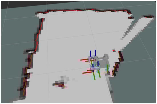
Figure 10.
Cartographer map generation in ROS2- RViz.
RViz functioned exclusively as a visualization tool in the ROS 2 framework, with trajectories and maps derived from actual sensor data from the DAMR in an indoor laboratory setting. No physics-based simulation methods, such as Gazebo, were employed for performance evaluation, and the ROS 2 Humble software stack was run on the real robot, while RViz visualized live sensor data, map creation, and trajectory estimation outcomes.
3.3. Experimental Tests
The tests were conducted on individual models, including wheel odometry, IMUs, and camera odometry, using RTAB-Map. Each test run provided a comprehensive and synchronized dataset of wheel odometry, IMU, and camera odometry measurements for evaluating the sensor framework. To evaluate the sensor framework strategies, tests were conducted on the DAMR to gather robot heading trajectory-aligned sensor data in realistic indoor conditions, assessing the performance of multi-sensor data integration techniques in estimating the robot’s pose over time.
The integration of sensor data was essential for implementing and assessing the discussed SLAM frameworks. The tests were conducted in an indoor laboratory, where the DAMR navigates for dual-arm grasping objects. During testing, the DAMR was manually operated with micro-ROS, enabling accurate navigation in the laboratory, as shown in Figure 11. After data collection from the test runs, sensor logs were processed offline to assess the effectiveness of sensor fusion for estimating the robot’s pose, following a defined processing pipeline. Time-stamped data from various topics was transformed into Matplotlib 3.10.8 compatible formats such as structured arrays and time series objects. The trajectories generated with individual sensor odometry and multiple combinations of sensor odometry fusion with EKF are presented in the following modules.
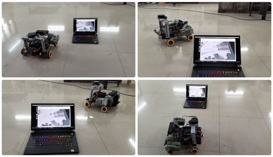
Figure 11.
DAMR testing in the indoor laboratory.
The experimental trajectory was designed to include straight segments, sharp angular turns, and loop-like motions within the indoor laboratory space. This structure was intentionally selected to expose typical localization weaknesses, including cumulative encoder drift during long straight motions, heading instability during rotations, and visual inconsistency during turning and feature-sparse regions. The trajectory therefore serves as a stress-test scenario rather than a random motion path.
To ensure reliability and repeatability, the experiments were conducted across five independent test runs under consistent environmental conditions. The displacement error and absolute trajectory error values are displayed in Table 1 and Table 2, which represent comparative evaluations across these repeated trials. By maintaining identical path geometry across tests, the study ensures fair performance comparison between individual sensors and sensor fusion with EKF configurations while minimizing variability due to environmental changes.
3.3.1. DAMR Reference Trajectory
The heading reference trajectory is generated using the robot’s pose information from the TF transform between the map and the base_link frames, which provides the robot’s planar position and orientation. This transform is generated by the localization and state-estimation stack, which processes data from various onboard sensors, including orientation from inertial sensing and translational pose from motion estimation. The trajectory node does not directly subscribe to raw sensor topics; instead, it uses the estimated pose from the TF tree to extract the yaw angle for the robot’s heading. By relying solely on the TF transform, the trajectory accurately reflects the robot’s estimated heading and forward motion while remaining independent of individual sensor implementations.
First, the LiDAR sensor begins sending distance measurements of the surrounding environment. The Cartographer node utilizes these measurements to comprehend how the robot navigates relative to nearby walls and obstacles. As the robot moves, Cartographer compares consecutive LiDAR scans and estimates the robot’s motion step by step. At the same time, Cartographer gradually builds a map of the environment. When the robot revisits an already scanned area, Cartographer corrects previous position errors and aligns the trajectory with the map. This process yields a stable and consistent map with a reliable reference trajectory for the robot’s movement. Figure 12 shows the DAMR trajectory generated in the RViz environment using Cartographer SLAM. This trajectory is constructed by continuously observing the robot’s pose from the TF transforms between the map and the base_link frames and extracting the yaw angle to determine the robot’s heading direction. Initially, the reference trajectory is initialized using the robot’s current position and heading. As the robot moves, changes in yaw are treated as pure rotational updates, allowing the reference trajectory to rotate smoothly in place whenever the robot turns. This ensures that orientation changes are reflected accurately in the reference path.
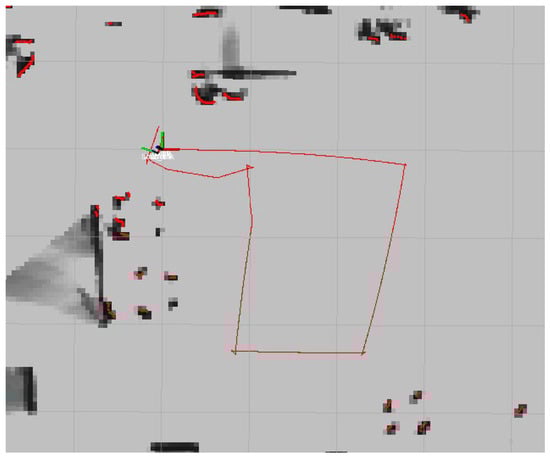
Figure 12.
DAMR reference trajectory generated in RViz.
The displacement measured between consecutive poses is projected onto the heading direction, ensuring that the trajectory advances strictly along the robot’s forward axis. This results in a motion path that follows the robot’s intended direction of travel. The time-stamped data collected from the map generated in RViz is converted into a MATLAB plot to analyse the trajectory, as shown in Figure 13.
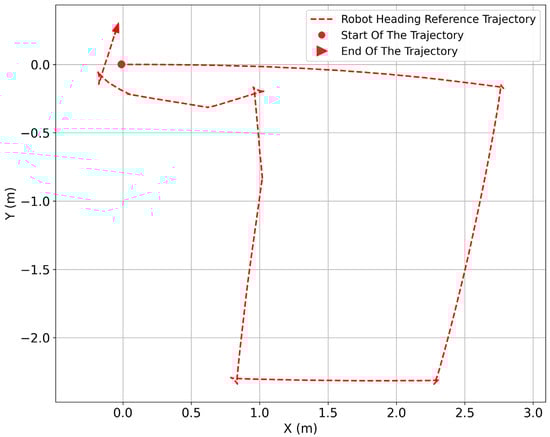
Figure 13.
DAMR reference trajectory generated in a MATLAB plot.
3.3.2. Wheel Odometry Trajectory
The DAMR was tested in an indoor laboratory. As the robot moves forward and turns, the wheel odometry continuously updates the robot’s position based on wheel motion. This method works well for short distances because the wheel rotations directly reflect the robot’s movement. At the same time, the robot’s heading direction is used to generate a separate reference trajectory. Figure 14 shows the DAMR trajectory generated by the wheel encoders’ odometry in the RViz environment using Cartographer SLAM and compared with the heading-based trajectory, which shows the expected direction of motion but does not account for the exact distance-travelled time.
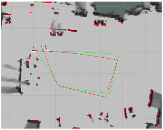
Figure 14.
Wheel odometry trajectory in Rviz.
Both trajectories are visualized together to compare their behaviour. Initially, the wheel odometry path closely follows the heading reference, indicating accurate motion estimation. As the robot continues to move and perform turns, small differences start to appear. These differences gradually increased because minor wheel slips and measurement errors accumulated in the wheel odometry, which effectively tracks short-term motion, as illustrated in Figure 15, although it diverges from the actual environment after extended paths, particularly when following loops. The heading reference trajectory aids in visualizing direction changes, but both methods fall short of correcting accumulated errors independently.
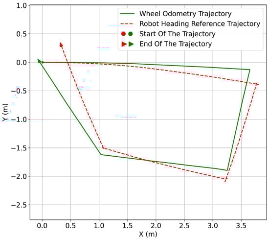
Figure 15.
Wheel odometry and reference trajectory in a MATLAB plot.
3.3.3. RTAB-Map Trajectory
RTAB-Map odometry utilizes RGB-D camera data to estimate robot motion by comparing successive camera frames. First, the RGB-D camera begins capturing visual and depth information from the surrounding environment. The RTAB-Map odometry node uses this data to estimate the robot’s movement by observing changes in the camera view as it travels through the environment. As the robot moves forward and turns, RTAB-Map compares consecutive camera frames and estimates the robot’s motion step by step. This process generates a continuous RTAB-Map odometry trajectory, which represents the robot’s movement based on visual information from the environment.
At the same time, the robot’s heading direction is used to generate a separate reference trajectory. Both trajectories, the RTAB-Map odometry trajectory and the heading reference trajectory, are visualized together. At the beginning of the motion, the two paths remain close to each other, as shown in Figure 16, indicating that RTAB-Map provides reliable short-term motion estimation.
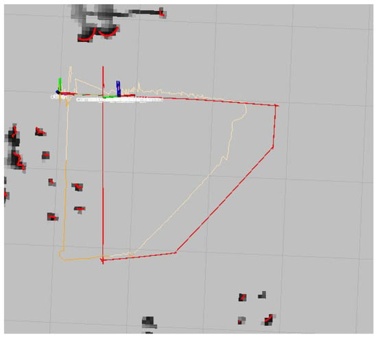
Figure 16.
RTAB-Map trajectory in RViz.
As the robot continues moving, minor variations begin to appear in the RTAB-Map trajectory due to changes in visual features, lighting conditions, and camera motion. When the trajectories are displayed on the map generated using LiDAR, the differences become more noticeable, as shown in Figure 17. RTAB-Map odometry generally follows the robot’s movement but does not perfectly align with the environment, especially after longer motions and turns. Unlike LiDAR-based SLAM, RTAB-Map odometry does not perform global corrections, resulting in small errors that gradually accumulate over time.
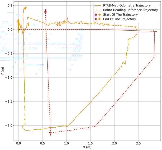
Figure 17.
RTAB-Map and the reference trajectory in a MATLAB plot.
Overall, this comparison demonstrates that RTAB-Map odometry offers detailed short-term motion estimation using visual data, while the heading reference facilitates the visualization of direction changes. The results highlight the limitations of visual odometry when used alone and emphasize the role of LiDAR-based SLAM as a stable reference for trajectory evaluation and future sensor fusion.
3.3.4. IMU Trajectory
Cartographer compares LiDAR scans to estimate the robot’s motion and gradually builds a map of the environment. When revisiting scanned areas, it corrects position errors, resulting in a stable map and reliable trajectory of the robot’s movement.
Concurrently, the IMU node publishes orientation information, generating a separate trajectory based solely on inertial measurements, as shown in Figure 18. This heading data is used to create a separate trajectory that represents how the robot’s motion would look if it relied only on inertial information. The comparison of the IMU-based trajectory with the reference trajectory is illustrated in Figure 19. The Cartographer trajectory stays aligned with the map, while the IMU trajectory slowly drifts over time, highlighting its unreliability for longer movements. The system effectively shows that LiDAR-based SLAM offers a stable navigation reference, with IMU data serving as a complementary source for motion analysis and sensor fusion.
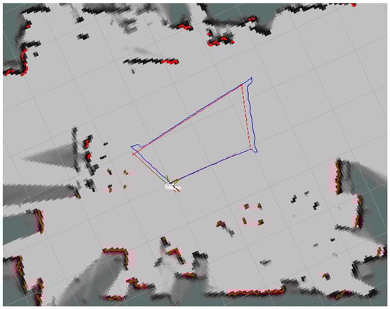
Figure 18.
IMU trajectory in RViz.
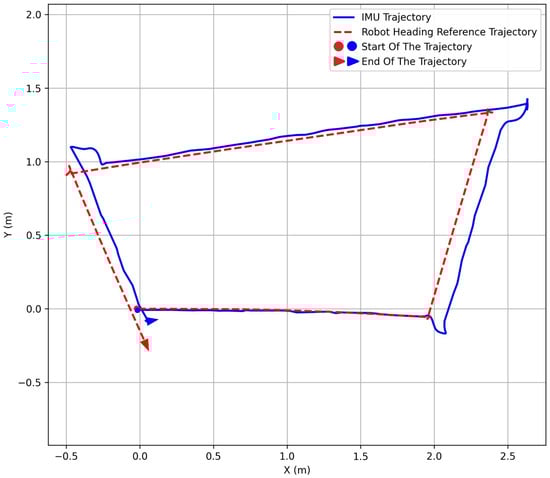
Figure 19.
IMU and reference trajectory in a MATLAB plot.
3.3.5. IMU and Wheel Odometry Fusion with EKF
As the robot moves, EKF combines wheel odometry and IMU data to estimate its position. Wheel odometry tracks distance and motion, while the IMU provides orientation updates during movement and rotation. Wheel odometry provides distance and motion on the ground, while the IMU contributes orientation changes. This integration yields a fused trajectory, as shown in Figure 20. Additionally, a heading-based trajectory indicates the expected direction of motion, independent of actual distance or corrections.
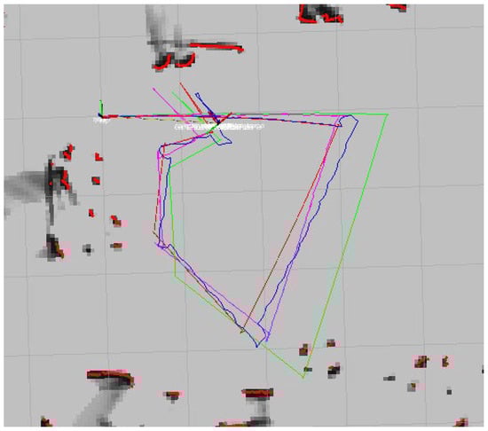
Figure 20.
Wheel odometry and IMU fusion with the EKF trajectory in RViz.
At the beginning, the EKF trajectory closely follows the heading reference, indicating that the fused estimation matches the intended motion direction. Both trajectories are visualized, initially aligning closely but diverging as the robot turns and moves. From Figure 21, the trajectory with EKF fusion is more closely aligned with the reference trajectory than the individual trajectories of the IMU and wheel odometry.
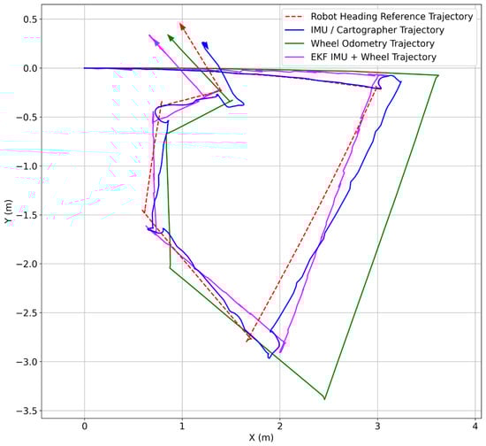
Figure 21.
IMU and wheel odometry fusion with the EKF trajectory in a MATLAB plot.
3.3.6. RTAB-Map and IMU Fusion with the EKF Trajectory
The sensor fusion with EKF continuously estimates the robot’s position by combining RTAB-Map odometry and the IMU information. RTAB-Map provides motion estimation based on visual and depth data from the camera, while the IMU contributes orientation and rotation information. Together, they produce a fused trajectory that represents the robot’s estimated motion. At the same time, the robot’s heading direction is used to generate a separate reference trajectory. Initially, the EKF trajectory aligns closely with the heading reference, indicating accurate estimation, as shown in Figure 22.
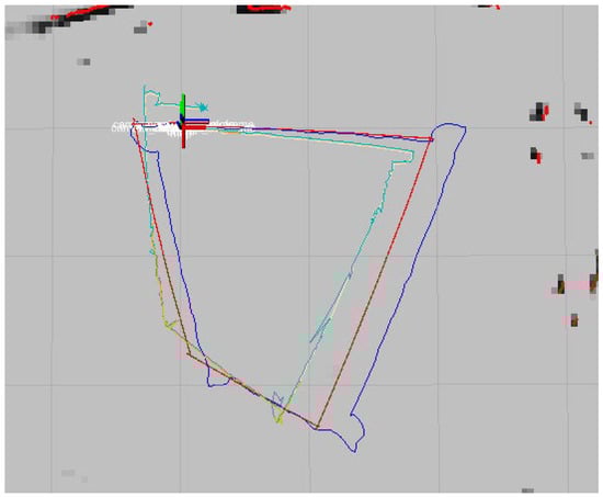
Figure 22.
RTAB-Map and IMU odometry fusion with the EKF trajectory in Rviz.
The EKF trajectory is noted for its greater smoothness and stability, particularly during turns, due to the IMU’s ability to mitigate abrupt orientation changes caused by visual disturbances, resulting in a more consistent path, as shown in Figure 23.

Figure 23.
RTAB-Map and IMU odometry fusion with the EKF trajectory in a MATLAB plot.
3.3.7. Multi-Sensor Fusion with EKF
The DAMR progresses with multiple motion estimation methods operating simultaneously with wheel odometry, the IMU, and RTAB-Map. These sources are consolidated using EKF to generate a unified trajectory, which is then visualized in the final map. Initially, the trajectories are closely aligned, indicating accurate estimations. As movement continues, discrepancies emerge; the IMU exhibits significant drift during extended straight moves and turns, while wheel odometry deviates due to wheel slip and the accumulation of errors. RTAB-Map effectively captures short-term motions but exhibits irregularities from visual noise and a lack of global correction. The EKF-fused trajectory, which integrates RTAB-Map, wheel odometry, and IMU data, demonstrates better alignment with the robot’s heading reference than individual sensor readings, as shown in Figure 24. It exhibits smoother turns, minimal drift, and improved consistency throughout the path. Notably, it mitigates the significant deviations encountered in the IMU and wheel-only trajectories during sharp turns and extended segments. Overall, the EKF trajectory closely mirrors the robot’s actual motion, with only minor offsets from the heading reference compared to the individual sensor trajectories.
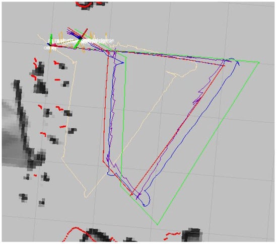
Figure 24.
Multi-sensor fusion with EKF trajectory generation in Rviz.
4. Results and Discussion
In this section, the results obtained from the real-time testing of the DAMR in the indoor laboratory with the proposed sensor framework are discussed and analysed. The trajectories obtained in the RViz environment are plotted in Figure 25. A detailed discussion is provided in the following subsections.
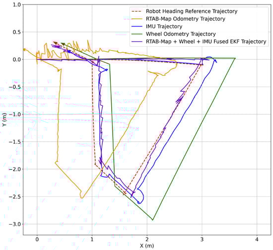
Figure 25.
Multi-sensor fusion with EKF trajectory generation in a MATLAB plot.
4.1. Analysis of the DAMR Trajectory Generated with EKF
The proposed sensor fusion framework with EKF was tested with the DAMR in an indoor laboratory, and the trajectories generated are plotted as shown in Figure 25 and analysed by a visual comparison of individual sensor trajectories, multi-sensor fusion with EKF-generated trajectories, and the reference trajectory, highlighting deviations in curvature, overshooting, and angular drift.
The heading reference trajectory was constructed by recording the time-synchronized pose values (x, y, and yaw) from this transform during the experimental runs. The time-stamped poses were then exported for offline processing, where individual sensor trajectories and the EKF-fused trajectory were aligned temporally with the reference before computing the displacement error and absolute trajectory error.
4.2. Displacement and Trajectory Error Estimation
The selection of trajectory evaluation aims to assess global drift and local deviations. The displacement error is normalized by the total travelled distance to reduce sensitivity to trajectory length and geometry, allowing fair comparison between experimental runs. However, since a single global metric may mask localized deviations, the ATE is additionally computed at discrete time instances. The ATE provides point-wise deviation between estimated and reference poses, capturing temporal variation in error growth. The combined use of these two complementary metrics ensures robust evaluation of localization performance without depending solely on averaged deviations.
The displacement error (13) calculated for the five experimental tests using various localization techniques is shown in Figure 26. The x-axis represents the test number, and the corresponding displacement error, expressed as a percentage of the total trajectory length, is displayed on the y-axis.
where D is the total distance travelled by the DAMR.
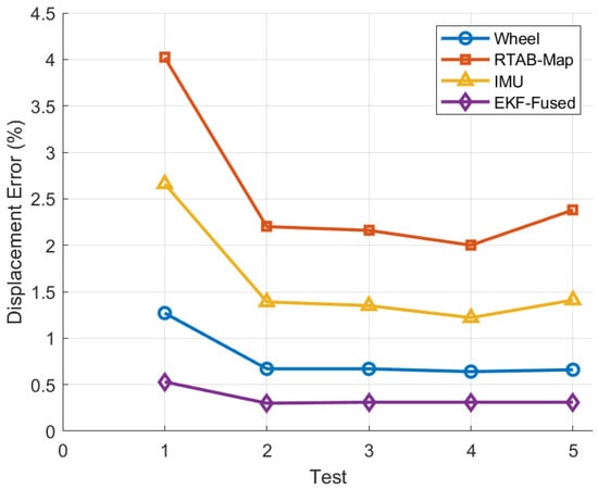
Figure 26.
Displacement error for individual sensors and sensor fusion with EKF.

Table 1.
Tests conducted to estimate displacement errors for individual sensors and sensor fusion with EKF.
Table 1.
Tests conducted to estimate displacement errors for individual sensors and sensor fusion with EKF.
| Test | Method | Δx (m) | Δy (m) | Δd (m) | Total Distance (m) | Displacement Error (%) |
|---|---|---|---|---|---|---|
| 1 | Wheel | 0.138 | −0.017 | 0.139 | 10.98 | 1.27 |
| RTAB-Map | −0.566 | −0.159 | 0.588 | 10.98 | 4.02 | |
| IMU | 0.239 | −0.155 | 0.285 | 10.98 | 2.66 | |
| EKF-Fused | 0.05 | −0.059 | 0.077 | 10.98 | 0.53 | |
| 2 | Wheel | 0.154 | −0.026 | 0.156 | 23.4 | 0.67 |
| RTAB-Map | −0.612 | −0.181 | 0.638 | 23.4 | 2.2 | |
| IMU | 0.265 | −0.173 | 0.316 | 23.4 | 1.39 | |
| EKF-Fused | 0.056 | −0.064 | 0.085 | 23.4 | 0.3 | |
| 3 | Wheel | 0.172 | −0.021 | 0.173 | 25.85 | 0.67 |
| RTAB-Map | −0.641 | −0.196 | 0.671 | 25.85 | 2.16 | |
| IMU | 0.281 | −0.189 | 0.338 | 25.85 | 1.35 | |
| EKF-Fused | 0.061 | −0.071 | 0.094 | 30.40 | 0.31 | |
| 4 | Wheel | 0.198 | −0.034 | 0.201 | 31.6 | 0.64 |
| RTAB-Map | −0.702 | −0.221 | 0.737 | 31.6 | 2 | |
| IMU | 0.312 | −0.214 | 0.378 | 31.6 | 1.22 | |
| EKF-Fused | 0.072 | −0.083 | 0.11 | 31.6 | 0.31 | |
| 5 | Wheel | 0.121 | −0.014 | 0.122 | 18.4 | 0.66 |
| RTAB-Map | −0.528 | −0.143 | 0.547 | 18.4 | 2.38 | |
| IMU | 0.214 | −0.137 | 0.254 | 18.4 | 1.41 | |
| EKF-Fused | 0.045 | −0.052 | 0.069 | 18.4 | 0.31 |
As a result of cumulative encoder-based drift, wheel odometry exhibits moderate error levels that vary depending on the test conditions. Due to frequent pose corrections and local trajectory distortions, RTAB-Map consistently displays the highest displacement error, as shown in Table 1. Although IMU-based localization performs better than RTAB-Map, it still experiences a slow increase in error due to inertial integration drift, especially in heading. The EKF-fused approach, on the other hand, continuously maintains the lowest displacement error throughout all tests, demonstrating its stability and resilience under a range of motion conditions.
The mean displacement error for each method, calculated across all five experimental tests, is displayed in Figure 27. The standard deviation is represented by error bars, which indicate the consistency of each approach. The highest mean error and significant variability are displayed by RTAB-Map, indicating inconsistent metric accuracy throughout the trials. Due to cumulative translational and rotational drift, wheel odometry and IMU-based localization exhibit moderate average errors with discernible variation. The EKF-fused approach demonstrates high accuracy and consistency, achieving the lowest mean displacement error with minimal standard deviation. The suggested EKF-based fusion strategy outperforms individual sensor modalities in maintaining accurate trajectory estimation, as this combined comparison unequivocally demonstrates.
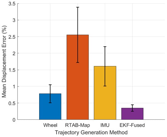
Figure 27.
Mean displacement error for individual sensors and sensor fusion with EKF.
- Absolute Trajectory Error
For each sample , the absolute trajectory error (14) is calculated for the individual sensors and for sensor fusion with EKF, as shown in Table 2 and displayed in Figure 28.
where
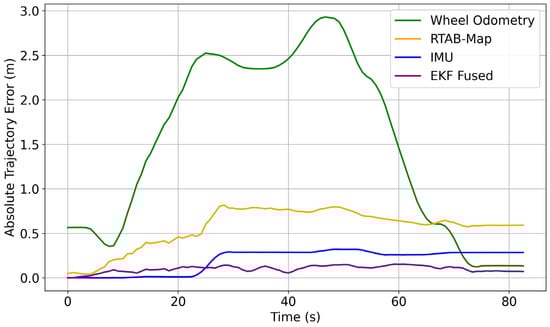
Figure 28.
Absolute trajectory error for individual sensors and for sensor fusion with EKF.
- : estimated pose at time ;
- : reference pose at time
Table 2.
Trajectory errors are estimated for individual sensors and sensor fusion with EKF.
Table 2.
Trajectory errors are estimated for individual sensors and sensor fusion with EKF.
| Time (s) | Wheel Odometry Error (m) | RTAB-MAP Odometry Error (m) | IMU Error (m) | Sensor Fusion with EKF Error (m) |
|---|---|---|---|---|
| 0 | 0 | 0 | 0 | 0 |
| 5.9 | 0.426 | 0.095 | 0.002 | 0.092 |
| 11.79 | 0.971 | 0.351 | 0.007 | 0.09 |
| 17.69 | 1.855 | 0.451 | 0.015 | 0.063 |
| 23.59 | 2.549 | 0.5 | 0.008 | 0.123 |
| 29.49 | 2.434 | 0.788 | 0.298 | 0.146 |
| 35.38 | 2.349 | 0.818 | 0.287 | 0.092 |
| 41.28 | 2.57 | 0.724 | 0.29 | 0.126 |
| 47.18 | 2.941 | 0.821 | 0.328 | 0.12 |
| 53.07 | 2.288 | 0.732 | 0.32 | 0.133 |
| 58.97 | 1.675 | 0.648 | 0.256 | 0.134 |
| 64.87 | 0.63 | 0.583 | 0.262 | 0.132 |
| 70.76 | 0.347 | 0.56 | 0.286 | 0.122 |
| 76.66 | 0.135 | 0.592 | 0.285 | 0.079 |
| 82.56 | 0.139 | 0.588 | 0.285 | 0.077 |
The experimental results clearly displayed the limitations of single-sensor modalities for trajectory estimation in indoor environments. Wheel odometry is reliable for short-term tracking but suffers from translational drift over longer paths due to wheel slip. IMU-based methods encounter significant orientation drift from inertial integration errors, while RTAB-Map odometry performs well over short segments but is inconsistent with lighting changes and lacks global correction. The EKF-based multi-sensor fusion approach effectively mitigates these issues by combining sensor strengths, resulting in improved smoothness, reduced drift, and better trajectory alignment. This integration enhances local stability and long-term pose consistency but may vary in dynamic or large-scale environments, warranting further investigation.
Video Link: Trajectory generation of DAMR in indoor laboratory https://drive.google.com/file/d/1WNUynoza_5M8BZiBdFZI6OpN4pFd2E5-/view?usp=drivesdk accessed on 15 January 2026.
5. Conclusions
In this paper, a novel SLAM methodology is proposed for DAMR trajectory generation, which combines RGB-D cameras, wheel odometry, and an IMU and is compared with the heading trajectory as a reference. The DAMR is simulated in the ROS 2 RViz environment and connected with a real model, which was operated manually with micro-ROS for smooth navigation of the robot in the indoor laboratory. The experimental tests were conducted with the DAMR with the following strategies:
- First, the DAMR heading reference trajectory is generated using the Cartographer SLAM framework, which publishes the map to the base_link transform, estimating the robot’s pose through internal sensor data and mapping. The heading reference trajectory node utilizes the pose estimate from the TF tree instead of raw sensor data, using extracted orientation and incremental motion to build a direction-constrained reference trajectory.
- This process yields a stable and consistent map with a reliable reference trajectory for the robot’s movement. After obtaining the reference trajectory, the DAMR was tested using the following combinations: individual sensor data, including wheel odometry, an IMU, and RTAB-Map odometry, to generate trajectories. This analysis concluded that the IMU shows significant drift during extended straight moves and turns. In contrast, wheel odometry deviates due to wheel slip and the accumulation of errors. RTAB-Map effectively captures short-term motions but exhibits irregularities due to visual noise and a lack of global correction.
- To reduce the errors produced, the DAMR was tested with the proposed approach, multi-sensor fusion with EKF, which integrates RTAB-Map, wheel odometry, and IMU data, demonstrating better alignment with the robot heading reference than individual sensor readings, as shown in Table 1 and Table 2. Individual sensors exhibit low trajectory errors in initial phases (t < 10 s: wheel odometry is 0.426 m, RTAB-Map is 0.095 m, IMU is 0.002 m and EKF is 0.092 m), peak during mid-duration (t = 40–50 s: wheel odometry is 2.941 m, RTAB-Map is 0.0821 m, IMU is 0.328 m and EKF is 0.12 m) due to cumulative drift in indoor navigation, and partially recover long-term (t > 80 s: wheel odometry is 0.139 m, RTAB-Map is 0.588 m, IMU is 0.285 m and EKF is 0.077 m) but still diverge from reference trajectory. The proposed EKF-based multi-sensor fusion exhibits a better mean displacement error of 0.352% and absolute trajectory error of 0.007 m, respectively, which is closest to the reference trajectory. It exhibits smoother turns, minimal drift, and improved consistency throughout the path. These metrics assessed the effectiveness of multi-sensor fusion with the EKF approach for reliable and accurate pose estimation in indoor navigation.
Although the proposed multi-sensor fusion framework demonstrates improved trajectory accuracy in indoor laboratory conditions, further investigation is required to validate its robustness in larger-scale and highly dynamic environments. Future work will focus on real-time optimization under computational constraints, adaptive sensor weighting strategies within the EKF framework, and integration of autonomous task-level control for coordinated dual-arm manipulation.
Author Contributions
Introduction/methodology/experimentation/writing/editing conducted by N.K.K.; Review and editing conducted by P.R.V. All authors have read and agreed to the published version of the manuscript.
Funding
This research received no external funding.
Data Availability Statement
The data presented in this study is available on request from the corresponding author.
Acknowledgments
During the preparation of this manuscript/study, the authors used Chat GPT-4o, Quill bot and Grammarly tools for the purposes of para-phrasing and the correction of grammar in sentences only. The authors have reviewed and edited the output and take full responsibility for the content of this publication.
Conflicts of Interest
The authors declare no conflicts of interest.
Abbreviations
The following abbreviations are used in this manuscript:
| SLAM | Simultaneous Localization and Mapping |
| DAMR | Dual-Arm Mobile Robot |
| EKF | Extended Kalman Filter |
| ROS 2 | Robot Operating System -2 |
| IMU | Inertial Measurement Unit |
| LiDAR | Light Detection and Ranging |
| RGB-D | Red, Green, Blue Depth |
| RViz | ROS Visualization |
| TF | Transform Frame |
References
- Tola, T.A.; Mi, J.; Che, Y. Mapping and Localization of Autonomous Mobile Robots in Simulated Indoor Environments. Frontiers 2024, 4, 91–100. [Google Scholar] [CrossRef]
- Trujillo, J.-C.; Munguia, R.; Albarrán, J.-C.; Arteaga, M. Control and monocular visual SLAM of nonholonomic mobile robots. Eur. J. Control 2025, 82, 101171. [Google Scholar] [CrossRef]
- Mao, H.; Luo, J. Approach to 3D SLAM for mobile robots based on point-line features and superpixel segmentation in dynamic environments. Measurement 2025, 247, 116742. [Google Scholar] [CrossRef]
- D’Alfonso, L.; Muraca, P.; Pugliese, P.; Grano, A. A decentralized Polynomial based SLAM algorithm for a team of mobile robots. IFAC Proc. Vol. 2014, 47, 10182–10187. [Google Scholar] [CrossRef]
- Xu, J.; Wang, D.; Liao, M.; Shen, W. Research of Cartographer Graph Optimization Algorithm Based on Indoor Mobile Robot. J. Phys. Conf. Ser. 2020, 1651, 012120. [Google Scholar] [CrossRef]
- Tian, C.; Liu, H.; Liu, Z.H.E.; Li, H.; Wang, Y. Research on Multi-Sensor Fusion SLAM Algorithm Based on Improved Gmapping. IEEE Access 2023, 11, 13690–13703. [Google Scholar] [CrossRef]
- Yarovoi, A.; Kwon, Y. Automation in Construction Review of SLAM for construction robotics applications. Autom. Constr. 2024, 162, 105344. [Google Scholar] [CrossRef]
- Shen, D.; Huang, Y.; Wang, Y.; Zhao, C. Research and Implementation of SLAM Based on LIDAR for Four-Wheeled Mobile Robot. In Proceedings of the International Conference of Intelligent Robotic and Control Engineering (IRCE), Lanzhou, China, 24–27 August 2018; IEEE: New York, NY, USA, 2018. [Google Scholar]
- Li, L.; Schulze, L.; Kalavadia, K. Promising SLAM Methods for Automated Guided Vehicles and Autonomous Mobile Robots. Procedia Comput. Sci. 2024, 232, 2867–2874. [Google Scholar] [CrossRef]
- Tee, Y.K.; Han, Y.C. Lidar-based 2D SLAM for mobile robot in an indoor environment: A review. In Proceedings of the International Conference on Green Energy, Computing and Sustainable Technology (GECOST), Miri, Malaysia, 7–9 July 2021; IEEE: New York, NY, USA, 2021. [Google Scholar] [CrossRef]
- Gao, Q.; Jia, H.; Liu, Y.; Tian, X. Design of mobile robot based on Cartographer SLAM algorithm. In Proceedings of the 2019 2nd International Conference on Informatics, Control and Automation (ICA), Hangzhou, China, 26–27 May 2019; IEEE: New York, NY, USA, 2019. [Google Scholar]
- Santos, M.; Rocha, R.P. An Evaluation of 2D SLAM Techniques Available in Robot Operating System. In Proceedings of the 2013 IEEE International Symposium on Safety, Security, and Rescue Robotics (SSRR), Linköping, Sweden, 21–26 October 2013; IEEE: New York, NY, USA, 2014. [Google Scholar] [CrossRef]
- Jeong, W.; Lee, C.; Lee, N.; Hong, S.; Kang, D.; An, D. Improving Sensor Adaptability and Functionality in Cartographer Simultaneous Localization and Mapping. Sensors 2025, 25, 1808. [Google Scholar] [CrossRef]
- Sobczak, Ł.; Filus, K.; Domańska, J.; Domański, A. Finding the best hardware configuration for 2D SLAM in indoor environments via simulation based on Google Cartographer. Sci. Rep. 2022, 12, 18815. [Google Scholar] [CrossRef]
- Yagfarov, R.; Ivanou, M.; Afanasyev, I. Map Comparison of Lidar-based 2D SLAM Algorithms Using Precise Ground Truth. In Proceedings of the 2018 15th International Conference on Control, Automation, Robotics and Vision, Singapore, 18–21 November 2018; IEEE: New York, NY, USA, 2018; pp. 1979–1983. [Google Scholar]
- Zheng, Z.; Xie, M.; Jiang, C.; Bian, H.; Wang, W. Indoor Mobile Robot Map Construction Based on Improved Cartographer Algorithm. In Proceedings of the 2024 WRC Symp Adv Robot Autom (WRC SARA), Beijing, China, 23 August 2024; IEEE: New York, NY, USA, 2024; pp. 470–475. [Google Scholar] [CrossRef]
- Ahmad, H.; Jahan, M.I.; Noh, M.M.; Amirul, M.; Azmi, H.; Hashim, A.I.; Hassan, M.K. Stochastic Mapping Analysis for Automated Guided Vehicles in ROS. In Proceedings of the 2025 IEEE 8th International Conference on Electrical, Control and Computer Engineering, Kuantan, Malaysia, 27–28 August 2025; IEEE: New York, NY, USA, 2025; pp. 257–262. [Google Scholar]
- Lin, M. Intelligent Filter-Based SLAM for Mobile Robots with Improved Localization Performance. IEEE Access 2019, 7, 113284–113297. [Google Scholar] [CrossRef]
- Li, F.; Fu, C.; Sun, D.; Li, J.; Wang, J. SD-SLAM: A semantic SLAM approach for dynamic scenes based on LiDAR point clouds. Big Data Res. 2024, 36, 100463. [Google Scholar] [CrossRef]
- Shen, Y.; Wang, S. Application of Slam Technology for Autonomous Mobile Robots in Complex Environments. Appl. Comput. Eng. 2025, 128, 108–112. [Google Scholar] [CrossRef]
- Erturk, H.; Tuna, G.; Mumcu, T.V.; Gulez, K. A Performance Analysis of Omnidirectional Vision Based Simultaneous Localization and Mapping. In ICIC 2012; LNCS 7389; Springer: Berlin/Heidelberg, Germany, 2012; pp. 407–414. [Google Scholar]
- Yang, L.; Cai, H. Enhanced visual SLAM for construction robots by efficient integration of dynamic object segmentation and scene semantics. Adv. Eng. Inform. 2024, 59, 102313. [Google Scholar] [CrossRef]
- Forster, C.; Zhang, Z.; Gassner, M.; Werlberger, M.; Scaramuzza, D. SVO: Semidirect Visual Odometry for Monocular and Multicamera Systems. IEEE Trans. Robot. 2017, 33, 249–265. [Google Scholar] [CrossRef]
- De Jesus, K.J.; Kobs, H.J.; Cukla, A.R.; Antonio, M.; Leite, D.S.; Tello, D.F. Comparison of Visual SLAM Algorithms ORB-SLAM2, RTAB-Map and SPTAM in Internal and External Environments with ROS. In Proceedings of the 2021 Latin American Robotics Symposium (LARS), 2021 Brazilian Symposium on Robotics (SBR), and 2021 Workshop on Robotics in Education (WRE), Natal, Brazil, 11–15 October 2021; IEEE: New York, NY, USA, 2021; pp. 216–221. [Google Scholar]
- Nan, J.; Intelligent, G.; Min, D. Implementation and research on indoor mobile robot mapping and navigation based on RTAB-Map. In Proceedings of the 2022 28th International Conference on Mechatronics and Machine Vision in Practice, Nanjing, China, 16–18 November 2022; IEEE: New York, NY, USA, 1988; pp. 1–6. [Google Scholar]
- Lin, C.-J.; Peng, C.-C.; Lu, S.-Y. Real-Time Localization for an AMR Based on RTAB-MAP. Actuators 2025, 14, 117. [Google Scholar] [CrossRef]
- Park, J.; Kim, J.Y.; Kim, B.; Kim, S. Global Map Generation using LiDAR and Stereo Camera for Initial Positioning of Mobile Robot. In Proceedings of the 2018 International Conference on Information and Communication Technology Robotics, Busan, Republic of Korea, 6–8 September 2018; IEEE: New York, NY, USA, 2018; pp. 1–4. [Google Scholar]
- Yin, J.; Luo, D.; Yan, F.; Zhuang, Y. A Novel Lidar-Assisted Monocular Visual SLAM Framework for Mobile Robots in outdoor environments. IEEE Trans. Instrum. Meas. 2022, 71, 8503911. [Google Scholar] [CrossRef]
- Zhao, Y.; Hong, Y. applied sciences Comprehensive Performance Evaluation between Visual SLAM and LiDAR SLAM for Mobile Robots: Theories and Experiments. Appl. Sci. 2024, 14, 3945. [Google Scholar] [CrossRef]
- Yang, M.; Sun, X.; Jia, F.; Rushworth, A.; Dong, X.; Zhang, S.; Fang, Z.; Yang, G.; Liu, B. Sensors and Sensor Fusion Methodologies for Indoor Odometry: A Review. Polymers 2022, 14, 2019. [Google Scholar] [CrossRef]
- Chen, L.; Hu, H.; McDonald-Maier, K. EKF based mobile robot localization. In Proceedings of the 2012 Third International Conference on Emerging Security Technologies, Lisbon, Portugal, 5–7 September 2012; IEEE: New York, NY, USA, 2012; pp. 149–154. [Google Scholar]
- Nasir, N.Z.M.; Zakaria, M.A.; Razali, S.; Abu, M.Y. Autonomous mobile robot localization using Kalman filter. MATEC Web Conf. 2017, 90, 01069. [Google Scholar] [CrossRef]
- Pei, F.; Zhu, M.; Wu, X. A decorrelated distributed EKF-SLAM system for the autonomous navigation of mobile robots. J. Intell. Robot. Syst. 2020, 98, 819–829. [Google Scholar] [CrossRef]
- Wang, Y.; Ye, C. Design of a logistics warehouse robot positioning and recognition model based on improved EKF and calibration algorithm. Syst. Soft Comput. 2024, 6, 200127. [Google Scholar] [CrossRef]
- Simanek, J.; Reinstein, M.; Kubelka, V. Evaluation of the EKF-based estimation architectures for data fusion in mobile robots. IEEE/ASME Trans. Mechatron. 2015, 20, 985–990. [Google Scholar] [CrossRef]
- Teng, X.; Shen, Z.; Huang, L.; Li, H.; Li, W. Multi-sensor fusion based wheeled robot research on indoor positioning methods. Results Eng. 2024, 22, 102268. [Google Scholar] [CrossRef]
- Mu, L.; Yao, P.; Zheng, Y.; Chen, K.A.I.; Wang, F.; Qi, N. Research on SLAM Algorithm of Mobile Robot Based on the Fusion of 2D LiDAR and Depth Camera. IEEE Access 2020, 8, 157628–157642. [Google Scholar] [CrossRef]
- Van Nam, D.; Thanh, P.; Huyk, C.; Kim, G. Fusion consistency for industrial robot navigation: An integrated SLAM framework with multiple 2D LiDAR-visual-inertial sensors. Comput. Electr. Eng. 2024, 120, 109607. [Google Scholar]
- Rahman, M.M.; Mahmud, J.A.; Sarker, S.K.; Yan, B.; Ali, M.F.; Rahim, M.A. ROS2-based real-time autonomous mapping and navigation: Integrating visual SLAM and sensor fusion with performance analysis under varying light. Measurement 2026, 268, 120695. [Google Scholar] [CrossRef]
- Hess, W.; Kohler, D.; Rapp, H.; Andor, D. Real-Time Loop Closure in 2D LIDAR SLAM. In Proceedings of the 2016 IEEE International Conference on Robotics and Automation, Stockholm, Sweden, 16–21 May 2016; IEEE: New York, NY, USA, 2016; pp. 1271–1278. [Google Scholar] [CrossRef]
- Taheri, H.; Qiao, B.; Ghaeminezhad, N. Kinematic model of a four Mecanum wheeled mobile robot. Int. J. Comput. Appl. 2015, 113, 6–9. [Google Scholar] [CrossRef]
- Rohrig, C.; Heb, D.; Kirsch, C.; Klinemund, F. Localization of an omnidirectional transport robot using IEEE 802.15.4a ranging and laser range finder. In Proceedings of the 2010 IEEE/RSJ International Conference on Intelligent Robots and Systems, Taipei, Taiwan, 18–22 October 2010; IEEE: New York, NY, USA, 2010; pp. 3798–3803. [Google Scholar] [CrossRef]


Disclaimer/Publisher’s Note: The statements, opinions and data contained in all publications are solely those of the individual author(s) and contributor(s) and not of MDPI and/or the editor(s). MDPI and/or the editor(s) disclaim responsibility for any injury to people or property resulting from any ideas, methods, instructions or products referred to in the content. |
© 2026 by the authors. Licensee MDPI, Basel, Switzerland. This article is an open access article distributed under the terms and conditions of the Creative Commons Attribution (CC BY) license.