1. Introduction
The automotive industry has been one of the main drivers of technological innovation, particularly in the fields of automation and robotics.
In recent years, the integration of vision systems into industrial or collaborative manipulators (cobots) has emerged as a promising solution to address challenges related to precision, flexibility, and efficiency in automotive production lines. This trend aligns with the Fourth Industrial Revolution, or Industry 4.0, which emphasizes the convergence of digital technologies with traditional manufacturing processes [
1].
Collaborative manipulators, unlike traditional industrial robots, are designed to work in direct proximity to human operators without the need for physical safety barriers [
1,
2,
3]. This feature is particularly advantageous in automotive production environments, where versatility and the ability to quickly adapt to different tasks are crucial. Additional benefits include space optimization, cost reduction associated with modifying assembly lines, and continuous process improvement through enhanced system knowledge and task optimization, driven by the integration of innovative solutions.
However, to fully realize the potential of cobot systems, it is essential to equip them with advanced vision systems that enable precise perception of the work environment and the execution of complex tasks with high accuracy.
Vision systems integrated into collaborative manipulators utilize cameras, depth sensors, and image-processing algorithms to analyze acquired images in real-time. Together, these components provide the robot with a detailed understanding of the three-dimensional space around it, enabling position corrections for tasks and the proactive detection of the presence or absence of objects within its workspace [
1,
4]. This capability is critical for operations such as inspection, component assembly, and parts handling, ensuring precision, high-quality, and reliable task performance compared to human operators.
This paper explores the use of a 3D vision system integrated into a collaborative robot (cobot) for performing tasks in the automotive industry. The cobot is also equipped with a screwdriver system specifically designed for nut-tightening operations.
A case study, aligned with the GreenAuto project, is presented to demonstrate the effectiveness of integrating various industrial devices alongside algorithms to correct positional uncertainties in the tightening system. This paper also includes an analysis of future trends and opportunities for the continuous improvement of such systems for other applications.
The main contributions of this paper are as follows:
Development of a method for correcting the positions of Cartesian points in a specific task applied to collaborative robots.
Analysis of different hardware components that can be integrated with cobots in their industrial operations.
The remainder of this paper is organized as follows:
Section 1 introduces the motivation behind this work and the challenges addressed.
Section 2 presents the state of the art, focusing on collaborative robots, vision systems, and advances in the literature that combine these technologies.
Section 3 provides an overview of the project framework within which this work is developed.
Section 4 details the hardware components involved and their roles in the practical case.
Section 5 outlines the proposed method for correcting the positions of bolts.
Section 6 describes the experimental tests conducted and the evaluation metrics used to analyze the method’s performance in detail.
Section 7 presents a discussion of the work, framing it within the challenges in the automotive industry and the work that has been developed.
Finally,
Section 8 discusses the results, highlights the contributions of this work, and offers suggestions for future research directions.
Brief Description of the Case Study
The case study involves fastening a partition plate, named “
Cloison”, as shown in
Figure 1, which is located inside commercial vehicles manufactured by Stellantis. This partition plate is positioned between the cargo area and the driver and passenger compartment. For successful implementation, the system to be developed must combine the information from the vision system with the positions of the cobot, which manipulates a screwdriving system to tighten a set of seven nuts.
The primary challenge addressed in this case study arises from the potential misalignment of the partition plate as it arrives on the assembly line. These misalignments create uncertainties in determining the exact positions for tightening nuts onto bolts. To overcome this, a 3D vision system was integrated, enabling precise adjustments and ensuring the accurate and reliable tightening of all bolts (as shown in
Video S1).
This approach aims to enhance productivity and elevate task quality, ensuring consistent final product standards. Moreover, it seeks to foster a safer and more ergonomic work environment for human operators in the automotive industry, allowing them to focus on more engaging and less repetitive tasks. By addressing both technical and human factors, this work contributes to advancing efficiency and worker well-being in industrial settings.
2. Related Work
This section presents the state of the art related to collaborative robots, vision systems, and finally, some examples of advancements related to the integration of cobots and vision systems.
2.1. Collaborative Robots
The modern industry is constantly evolving, driven by an incessant demand for operational efficiency, increased productivity, and a rigorous workplace safety process. However, dedicated industrial tasks can be complex, strenuous, and repetitive. When these tasks are performed solely by human operators, this can lead to efficiency, consistency, and precision issues, due to factors such as fatigue, distraction, or other human-related issues. In this context, collaborative robots have emerged as a promising solution to mitigate such problems, working alongside humans and fostering a safer and much more efficient work environment [
5,
6].
Cobots were developed to interact safely with humans, sharing the workspace in collaborative or cooperative tasks. These types of robots offer high flexibility and adaptability, being able to be reprogrammed or adjusted quickly compared to traditional robots, and can be used in various tasks, allowing their application in a wide range of industrial scenarios [
5].
In comparison with conventional industrial robots, cobots offer several advantages. They are inherently safer, as they are designed to operate alongside humans without the need for extensive safety barriers, reducing the workspace required and promoting a more integrated environment. Additionally, cobots are more flexible, allowing quick adjustments and reprogramming, which makes them ideal for small-scale production or frequently changing tasks. Their ease of use and lower implementation costs further enhance their appeal, particularly for smaller industries or specific applications, such as the tightening of the cargo separator analyzed in this paper.
2.2. Computer Vision Systems
In recent years, the demand for 3D optical sensors has driven the development of computer vision systems, particularly in robotic applications, where they are used to provide a three-dimensional perception of the environment and object manipulation [
7].
Different technologies can be used for 3D image acquisition, each with its advantages and challenges. The current literature highlights that the main technologies used in this industry are as follows:
Photogrammetry, which is highly accurate but faces challenges such as automation and cost-effectiveness, often used in the automotive industry for measurements, allowing, for example, the detection of deformations and control or inspection of manipulated parts [
8].
Time-of-flight (ToF) systems and structured light, which allow real-time 3D image acquisition and are compact solutions very useful in collaborative robotics, although they have limitations in terms of size and application [
8,
9].
Laser systems through triangulation, on the other hand, provide more accurate identification of parts to be detected, as in welding processes.
Two-dimensional cameras are more sensitive to lighting variations but are still widely used for object identification despite the mentioned limitations [
10,
11].
Vision systems are essential in operations that require movement. In these cases, robotic systems, widely used in modern factory automation, can be applied to various tasks such as object assembly. However, they face several technical challenges, such as variations in the surfaces of objects to be handled and different lighting conditions [
12]. Thus, the implementation of vision systems that integrate different sources of information, such as stereo vision, infrared, and RGB cameras, is a promising solution to improve the accuracy and robustness of these systems.
The evolution of integrated solutions that acquire three-dimensional information can help robots perform specific tasks, such as automotive component assembly. Many of these applications are still under development, always aiming to improve productivity and offer a competitive advantage to companies investing in innovation [
13]. Furthermore, the ability to adapt vision systems to different environmental conditions and work situations, through the use of adaptive algorithms and deep learning techniques, makes it possible to optimize the performance of operations in real-time.
2.3. Advancements in the Integration of Cobots with Vision Systems
Due to the highly technological nature and complexity of various industrial assembly processes, it can be challenging to promptly adapt to evolving demands in a dynamic market. As a result, manufacturers now face a great need in modernize their infrastructures to remain competitive in a global market. One option to achieve the required levels of efficiency and flexibility is the integration of cobots with intelligent vision systems into the manufacturing processes. In recent years, significant advancements have been made, as presented by various researchers.
For example, Yang X. et al. developed a production automation framework aimed at small and medium-sized enterprises (SMEs) using cobots with a vision-based perception system. The vision system employs an object detection algorithm, YOLOv5. They also created a multifunctional gripper to perform multiple operations, eliminating the need for tool changeovers. Experimental tests assessed the system’s effectiveness in optimizing processes, demonstrating a high potential for applications in SMEs [
14]. In [
15], the authors proposed the use of a commercial platform for industrial tasks, specifically for a pick-and-place application with objects of various sizes from a conveyor belt, with a random order and timing. The system enables real-time trajectory planning for two robots simultaneously, using a 3D vision system to perform the object pick-and-place. Similarly, in [
16], the authors proposed a system called “Deep Visual-Servoing (DVS)”, which combines deep learning based on convolutional networks (deep-ConvNet) with 3D visual control for robotic manipulation. This approach includes 3D position estimation using an RGB camera, where the estimated position data are used to control the joint velocities of a robotic manipulator. In [
17], the authors present a vision-based robotic assembly system, focusing on the assembly of components for mobile phone screens. The challenges addressed include object calibration and the handling of moving parts with incomplete information. The system uses cameras to detect and position the parts.
In the field of vision-based automation, Biegelbauer G. et al. developed a robotic hole inspection system based on 3D vision, designed to automate the insertion of an endoscope into industrial parts and ensure quality inspection. The system uses a 3D laser scanning sensor to correct positioning deviations and a camera attached to the endoscope to capture internal images of the holes [
18]. Similarly, in [
19], the authors developed a robotic system to address the
bin-picking problem, aiming to overcome the limitations of current solutions. The system consists of a 6-DOF industrial robot, a 3D vision system mounted on a movable linear frame, and an end effector based on a gripper or vacuum, depending on the objects. They used a SICK Ranger E camera with linear laser projectors to avoid shadows and obtain precise 3D data.
3. The GreenAuto Project
This work is part of the Pilot Project (PPS 17: EIBOT and AGV Supervision System) of the GREENAUTO project (Green Innovation for the Automotive Industry), which aims to position the national automotive industry within the value chain of low-emission vehicles. To achieve this goal, innovative, digital, and sustainable products and processes related to the manufacturing of automobiles and their components will be developed. This article addresses one aspect of this project, co-financed by the PRR (Recovery and Resilience Plan), the Portuguese Republic, and primarily by the European Union. In order to improve the efficiency of the production process, the critical point identified is the use of collaborative robots in the fastening process, which is the subject of intervention and resolution in this project. Finally, the development of this paper is in partnership with PEUGEOT CITROËN AUTOMÓVEIS PORTUGAL, S.A. (“STELLANTIS Mangualde”), and this project is Project Investment No. 54, AAC No. 02/C05-i01/2022 [
20].
4. Prototype System Description
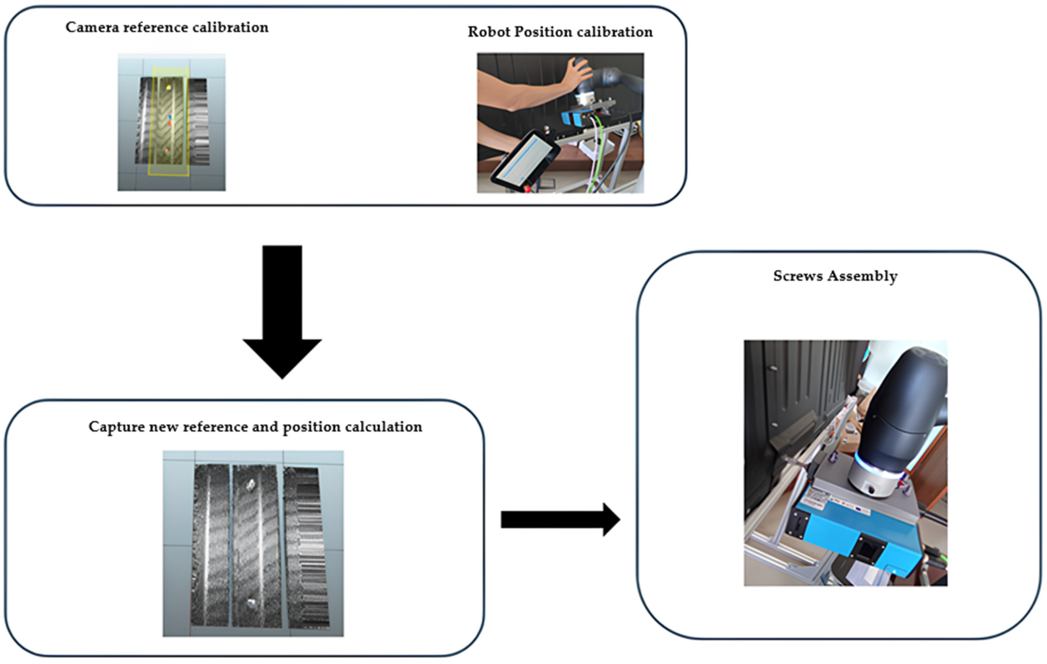
Figure 2 shows the arrangement of all elements forming the prototype of the system developed for the assembly of screws on the Cloison plate. The assembly process is divided into four distinct steps:
Calibration of a reference: First, a reference calibration is performed between the vision system (which is attached to the cobot’s tool) and the Cloison plate. In this step, an acquisition is made using the vision system through a linear movement of the cobot to obtain the positions of the Cloison. Then, the position of each screw is manually defined according to the reference given by the camera. This completes the calibration, and the system is now ready to make future position corrections for another Cloison from a different vehicle or when there are deviations in the Cloison plate. It is important to note that this process is only performed once.
Detection of a new reference: In this step, the system’s work cycle is initialized, and the acquisition begins through the vision system. Once the acquisition is completed, the points of the new reference are obtained.
Position adjustment: After obtaining the reference of the new Cloison, the robot’s position is calculated and adjusted. A set of calculations is performed to obtain the data for the inverse kinematics calculation, which adjusts the robot’s position to carry out the screw-tightening movement. In this way, the references from point A are compared with the references from point B.
Screw tightening: The tightening of the screws can only be performed after calculating the new positions of all screws based on the obtained references. Then, the screws are tightened at the correct positions.
The assembly of screws on the Cloison partition plate incorporates the following architecture of elements (which, in turn, are further discussed in detail in the following sub-sections):
4.1. Mechanical Structure
The structure in
Figure 3 was assembled to simulate the position of the plate (
Cloison) inside vehicles. The plate is fixed to a structure, and the robot’s base is also attached to this structure, which is made of aluminum profiles. Since the robot’s base is fixed to the plate structure, it is possible to perform vision system tests. The plate is fixed in such a way that its lateral position can be adjusted, simulating position errors of the Cloison. This setup allows for a testing structure that reflects the assembly line process, enabling the execution of various tests to ensure the system is robust and reliable in its application.
4.2. Doosan Collaborative Robot
The robot used for this case study is called Doosan M1013 (with the specifications listed in
Table 1). This is a cobot developed by Doosan, designed to work safely in shared and collaborative spaces. The robot has six axes, allowing it to be used in various applications, such as assembly, packaging, quality inspection, and material handling [
21].
4.3. Vision System SICK TriSpector 1030
The SICK Trispector 1030 vision system is a compact and robust 3D system designed for industrial applications that require precise and automatic inspection. This vision sensor can acquire and process three-dimensional images of moving objects with high processing capability, making it suitable for a variety of tasks such as quality control, volume calculation, presence detection, and part positioning [
22]. The specifications of the equipment can be found in
Table 2.
4.4. Screw-Tightening System
The screw-tightening system is divided into two distinct components: the controller and the screwdriver. The screwdriver is the Desoutter ECS10-M20, Ets Georges Renault, Saint-Herblain, France, which is driven by the Desoutter CVIIC 2 controller.
It allows real-time monitoring, ensuring quality and consistency, and also facilitates integration with other automation systems in the factory.
Table 3 shows the specifications of this controller and
Table 4 the screwdriver system.
5. Detection and Compensation of Screw Misalignment
This section describes in detail the methodology used to detect and compensate for misalignments in the positions of the screws. The method consists of four steps:
Tightening the nuts at the indicated location (
Section 5.4).
5.1. Calibration of Reference
The calibration process is only carried out once, i.e., it is performed at the moment the robot is installed in its work area, along with its respective components. The calibration of a new reference mainly involves determining a coordinate system for the robot’s base (B), a coordinate system for the vision system (C), and a coordinate system for the Cloison plate (P). Each coordinate system consists of an X-axis, a Y-axis, and a Z-axis, as shown in
Figure 4.
Once the coordinate systems are defined, the reference is obtained with the help of the SOPAS Engineering Tool software from SICK. This software was developed by SICK and is used for configuring, parameterizing, and diagnosing sensors and automated systems in the field of sensing. It is widely used in industrial environments, offering an intuitive graphical interface that facilitates the connection and configuration of various SICK devices, such as vision sensors, LiDARs, and safety systems.
To do this, the robot must perform a movement along the Y-axis, that is, a movement of the type (from left to right), while the camera acquires data, as shown in
Figure 5. The image acquisition for the reference is triggered by a signal from the robot that is received by the camera, and only after this signal is the acquisition performed, thus completing this step.
After the reference image is obtained, and to determine the future displacements of the Cloison plate, the positions of two of the screws were defined as a reference, in this case, the third and fourth screws (from
Figure 1). These specific screws were chosen because they are strategically positioned, ensuring greater accuracy in identifying and compensating for possible displacements of the plate. Thus, processing was performed in the SOPAS software to detect the screws in question. After the scan performed by the camera, the following point cloud is received on the SOPAS software side, as shown in
Figure 6.
Next, the data obtained from the reference image are processed using a
Shape tool. In this tool, a region of interest (as shown in
Figure 7) must be defined. and this area was previously defined with the necessary dimensions to collect useful information for the application, while also ensuring that the system is fast enough to perform the task. This area is to be used as a reference image to be detected in real-time during operation so that the relative positioning and orientation of the “
Cloison” with respect to the manipulator can be determined. The area of this image should include distinctive features and be large enough to allow successful discrimination of the reference area by the vision system, but also be small enough so that the computational burden is not excessive and negatively impairs online, real-time operation. This function is typically used when the position or rotation of the object may vary, which is the case in this test scenario.
After obtaining the shape of the object, other functions are associated within the Shape tool. One of them is the Area function (as illustrated in
Figure 8). The Area function calculates the area of the shape, which is essentially the surface of the Cloison, by counting points within a defined 3D region or within a specified intensity range in the region. This function is used to verify that when an area scan is performed, it corresponds to the desired area.
The final step is the use of a function called
Blob, which is part of the
Shape function (as shown in
Figure 9). This
Blob function locates clusters of points within a defined height range and calculates the size of a specific cluster. It allows for measuring the volume, area, angle, and bounding box of the image, as shown in
Figure 9. In this way, this function was used to detect the positions of the screws relative to the camera reference, as well as the number of blobs detected within the region of interest. The
Blob function was configured to create clusters around areas ranging from 10 mm
2 to 28 mm
2. The result of the function is the position of each cluster found (with each cluster representing the position of a screw) along the X, Y, and Z axes, as well as the area of each cluster, meaning the size of each screw.
Finally, the last step of the calibration involves manually defining the positions of all the screws in the robot’s base reference frame in relation to the screwdriving tool, in order to perform the tightening. In this way, the positions are referenced as shown in
Table 5, and they will be defined to later apply the correction method developed, which will be addressed in
Section 5.3.
The robot positions for tightening the screws were defined based on the reference positions of the screws, as shown in
Table 6, provided by the camera (in this case, by the
Blobs tool). These reference positions are used as a base to correct the positions for subsequent iterations on vehicles that have the
Cloison plate.
5.2. Detection of a New Reference
This step marks the beginning of the work cycle. Here, the robot will perform a new linear movement along the Y-axis and obtain a new point cloud, as shown in
Figure 10, so that the vision system can acquire the surface of the
Cloison to obtain a new reference of the screws and later compare it with the first reference.
After acquiring the point cloud from the
Cloison, the functions described in the previous subsection are applied. For instance, for the scan performed in
Figure 10, the following parameters were obtained, as shown in
Table 7. After acquiring the data from each function, a process is carried out to calculate the correct position of the robot in relation to the reference screws.
5.3. Calculation and Adjustment of the Robot’s Position
The next step involves calculating the positions of the screws based on the data provided by the vision system. The data are sent from the vision system through the SOPAS Engineering Tool software to the Dart Studio software via sockets, as shown in
Figure 11.
The data sent via socket consist of a frame (as shown in
Figure 12) containing information about the acquired data from the vision system. The frame includes data on the acquisition area, the number of detected blobs, and the position of each blob.
After data reception, a position adjustment process is carried out. The position adjustment is based on verifying the deviation of the screw positions on each axis. In this case study, deviations primarily occur on the Y-axis, as illustrated in
Figure 13.
The inverse kinematics calculation is only performed after obtaining the displacement, which is the difference between the data obtained from the camera (coming from the data frame) and the data defined in the reference calibration
However, the variable only represents the variation in the camera data, which does not accurately reflect the actual displacement in the robot’s base reference frame. This discrepancy can result from potential misalignments between the vision system and the manipulator over different sessions. To address this, the alignment of the system’s axes is verified, and an offset is applied to the respective axis.
This offset is calculated using inverse linear interpolation, which maps the discrepancy to the actual variation in the robot’s Y-axis position. The process relies on two precisely measured reference points: the first point (x1,y1) is obtained during the initial calibration process directly on the Cloison plate, and the second point (x2,y2) is obtained from additional measurements taken during operation. These measurements allow for a precise mapping of the variation along the Y-axis by establishing a relationship between the observed differences in the camera data and the actual robot base displacements.
The equation used to calculate the offset
was the following:
In this formula, y1 and y2 represent the known reference positions, while x1 and x2 represent the observed variations at those same points. The variable represents the difference between the position measured by the camera and the position defined during the reference calibration. To ensure numerical stability, this formula assumes x1 ≠ x2.
By applying this method, the alignment of the robot’s reference frame is maintained across sessions, ensuring that the Y-axis variations are accurately compensated. This approach is particularly useful for correcting misalignments during operation and represents a practical contribution to trajectory correction for robotic systems.
Inverse linear interpolation allows for precise adjustment of the actual position of the screw along the Y-axis, compensating for any deviations detected during measurement. By applying this method, it was possible to calculate the exact displacement of the robot, enabling it to perform the task of tightening the nuts onto the screws, regardless of minor variations in the assembly line of the positioning and orientation of the Cloison plate.
Finally, only the offset value is added to the robot’s position to complement any deviations that may occur in the system.
It should be noted that the same process can be applied to the X and Z axes if there are discrepancies between the expected position and the position measured by the camera. Thus, based on the proposed algorithm, the system provides the X, Y, and Z positions with the respective offset to be applied to each axis (if applicable). In this way, the desired robot’s end-effector position
,
, and
can be computed. Inverse kinematics are used to calculate the joint angles necessary to reach the adjusted position in Cartesian space, ensuring that the end-effector aligns correctly with the desired point. Thus, this approach involves dividing the transformation
:
represents a homogenous transformation matrix corresponding to the desired end-effector position P and rotation R. Expanding P and R in (3), we find that
will take the following form:
The robot will execute the corresponding trajectory, which will place the screw tightener in the correct location to fasten the nuts.
5.4. Screws’ Assembly
The overall process of assembling the nuts onto the bolts is depicted in
Figure 14. Here, a calibration of a reference is performed, where this reference corresponds to two screws on the partition plate, denoted as screw nº3 and screw nº4. For the calibrated reference, the positions that the robot must move to are determined, and these positions are also used as a reference. Subsequently, an acquisition is performed with the vision system, where the trigger is activated by the robot to obtain the point cloud. Afterward, processing is carried out and compared with the reference data. Finally, the data from the camera are converted into data for the robot to calculate the new positions, and the robot performs the assembly of the nuts on the partition plate.
6. Experimental Validation
Experimental validation tests were conducted to validate the robustness of the approach described in
Section 5.
Specifically, we aim to experimentally determine if the approach offers robust results in the presence of variations in the distance between the “Cloison” and the manipulator, along the y-axis (perpendicular to “Cloison”). This capacity is important because the distance from the manipulator across this axis is more challenging to account for than variations across other dimensions, as those manifest more directly and explicitly in the two-dimensional point map image that is used for reference purposes.
To achieve this, we designed an experimental procedure to assess the capacity of the algorithm to correctly estimate the screw position for various scenarios with varying distances from “Cloison” to manipulator. Three tests of the system were conducted under different testing conditions, as follows:
Scenario 1: Under favorable lighting conditions, meaning the test environment had bright light.
Scenario 2: Under unfavorable lighting conditions, meaning the test environment had low light.
Scenario 3: Under favorable lighting conditions with vibrations applied throughout the test.
To achieve this, we displaced the partition plate by various distances and executed the work cycle for each one. For each distance, five iterations were performed in each test scenario.
As evaluation metrics, the maximum distance (Max) between the reference value and the calculated value was used, as well as the Root Mean Square (RMS) metric. The maximum distance metric evaluates the largest error between the reference value and the calculated value in the five iterations performed for each distance at each screw, while the RMS calculates the mean squared error, providing an overall view of the system’s accuracy across multiple iterations.
Thus, the first test conducted corresponded to
Scenario 1.
Figure 15 and
Figure 16 present the
Max and
RMS values, respectively, for the seven screws at different distances, ranging from 0 mm to 15 mm in 3 mm increments along the Y-axis of the “Cloison” plate.
A significant variation in measurements is observed depending on the distance and the nut analyzed:
Nut 1: For a distance of 0 mm, the MAX value was 0.96 mm and the RMS was 0.57 mm, indicating a small discrepancy between the calculated value and the reference value. However, for larger distances, such as 12 mm and 15 mm, the MAX and RMS values decreased to 0.58 mm and 0.37 mm at 12 mm, and to 0.57 mm and 0.49 mm at 15 mm, showing that the algorithm’s accuracy improved with an increasing distance for this nut.
Nuts 2 to 7: The remaining nuts showed a similar pattern in the behavior of the MAX and RMS metrics. For a distance of 0 mm, the MAX value was consistently higher, reaching 2.46 mm, while the RMS was 2.00 mm. With increasing distances, the MAX varied between 1.19 mm and 2.17 mm, and the RMS between 0.84 mm and 1.78 mm, evidencing a more pronounced variation at larger distances.
In general, the algorithm exhibited smaller errors at larger distances for Nut 1, while for Nuts 2 to 7, errors remained higher at intermediate distances (3 mm and 6 mm) before stabilizing at larger distances (12 mm and 15 mm). This behavior can be explained by the increased complexity in reading positions at shorter distances, where interferences tend to be more significant.
Next, the test for
Scenario 2 was conducted, where the lighting conditions were unfavorable, meaning the robot’s working environment was dark.
Figure 17 and
Figure 18 graphically present the values obtained in this scenario. When analyzing the results, the following observations can be made:
Nut 1: Relatively low errors at the beginning (MAX = 0.81 mm, RMS = 0.50 mm at 0 mm). Accuracy remained stable between 3 mm and 9 mm, but errors increased at 15 mm (MAX = 1.00 mm, RMS = 0.69 mm).
Nuts 2 to 7: High errors from the start (MAX ≈ 2.31 mm, RMS ≈ 1.76 mm at 0 mm). Between 3 mm and 9 mm, values fluctuated moderately. However, at 15 mm, errors significantly increased (MAX = 5.41 mm for Nut 2), indicating greater difficulty for the algorithm in low-light conditions.
The measurements showed significant error variations, suggesting that low lighting conditions compromised result stability. While MAX and RMS values fluctuated with distance, the sharp increase in errors at 15 mm indicates that the algorithm struggled to correctly identify the screws as the distance increased.
Comparing the two scenarios presented, it is evident that Scenario 1 provided more precise and stable measurements, with a slight improvement in accuracy as distance increased. In contrast, Scenario 2 resulted in greater errors and measurement instability, with a sharp increase in errors at larger distances, especially beyond 12 mm.
Thus, it is clear that favorable lighting conditions significantly influenced measurement accuracy, while unfavorable lighting had a substantial impact. However, despite the existing errors, the robot was still able to successfully tighten the screws, highlighting the robustness of the developed algorithm.
Finally, a last test was conducted to assess potential error scenarios that may occur during assembly on the factory floor. Scenario 3 was designed to evaluate the robustness of the developed algorithm by introducing vibrations to the Cloison partition plate while the robot performed the scanning process with the vision system and tightened the nuts.
Figure 19 and
Figure 20 graphically present the obtained RMS and MAX values, respectively. Based on the results, the following observations were made:
Nut 1: Errors increased compared to the previous scenarios. MAX was 1.25 mm at 0 mm and rose to 2.77 mm at 15 mm, indicating that vibrations affected accuracy, especially at larger distances.
Nuts 2 to 7: At 0 mm, errors were already high (MAX ≈ 2.75 mm, RMS ≈ 2.19 mm). As the distance increased, errors fluctuated between 1.52 mm and 2.62 mm, but at 15 mm, values increased significantly (MAX = 4.27 mm, RMS = 2.90 mm).
Although the vibrations led to an increase in errors, the algorithm remained functional, allowing the robot to successfully tighten the nuts. This demonstrates that the system possesses significant robustness and is capable of operating effectively even under interference conditions such as vibrations.
7. Discussion
The research conducted presents an innovative approach to integrating 3D vision systems in collaborative robots, focusing on position correction for industrial tasks. The proposed solution stands out for its real-time adaptability, integrating inverse kinematics algorithms with high-precision 3D sensors. The scientific relevance of the developed method lies in its versatility, allowing its application across various industrial processes, extending beyond the specific case of nut tightening on partition plates of commercial vehicles.
The system’s robustness has been validated in different scenarios, demonstrating its ability to handle uncertainties and variations in industrial conditions. This characteristic is essential for its scalability and applicability in other processes, such as welding, quality inspection, component assembly, polishing, painting, and object manipulation. The necessary adaptations for transferring the method to other tasks mainly involve three aspects: (i) replacing the working tool; (ii) modifying the software for re-calibrating vision algorithms; and (iii) adjusting the hardware to ensure compatibility with the specificities of each industrial environment.
The compatibility of the integrated hardware with other production line equipment is a relevant factor for its implementation in different manufacturing contexts. However, some challenges arise when integrating this system into other automotive production processes, such as compatibility with existing communication interfaces, the need for sensor adjustments to accommodate different lighting conditions and component sizes, and software modifications to optimize calibration and component identification.
Experimental tests demonstrated that the developed algorithm maintains a satisfactory performance even under adverse conditions, particularly in low-light environments and with vibrations. The analysis of the results showed that, in low-light scenarios, errors slightly increased, with a noticeable upward trend at greater distances due to the sensor’s difficulty in identifying reference points with the same level of precision. Similarly, in the vibration scenario, a more significant increase in error was observed compared to the previous perturbation scenario. However, the system remained functional, correctly identifying positions and successfully tightening the nuts.
These results confirmed that the algorithm possesses sufficient robustness to operate in real industrial environments, where such perturbation scenarios are common. Furthermore, the system’s ability to maintain functionality and operability under these conditions reinforces the reliability of the adopted approach, demonstrating that these variations do not compromise the final objective of the task.
From an economic perspective, the cost–benefit analysis highlights that, despite the higher initial investment of the automated solution compared to manual tightening, the long-term benefits are significant. Automation reduces recurring operational costs, minimizes failures, and increases production efficiency. The economic feasibility of the solution will depend on the specific conditions of each industrial environment and the degree of adaptation required.
Thus, the research aligns with the concepts of Industry 4.0 and 5.0, promoting flexible and scalable solutions for optimizing production processes. The contribution of this work is not limited to the analyzed case study but establishes a generic architecture that can be replicated across different industrial sectors, reinforcing the integration of advanced technologies in modern manufacturing.
8. Conclusions and Future Work
The findings of this case study highlight the successful integration of advanced automation technologies into an industrial environment, demonstrating the viability of combining collaborative robots, 3D vision systems, and specialized tools like screwdrivers for precision tasks. The system achieved high performance, with errors and deviations remaining within acceptable limits, showcasing its reliability and adaptability for real-world factory applications.
Beyond the specific task of nut tightening on partition plates, this work illustrates how automation can address key challenges in manufacturing, such as precision, repeatability, and process optimization. The demonstrated flexibility of the system underscores its potential to be adapted for other applications across production and assembly lines, paving the way for smarter and more versatile industrial solutions. Furthermore, the system’s ability to optimize cycle times and enhance productivity aligns directly with the increasing demands for efficiency and quality in modern manufacturing.
Importantly, this work also addresses the human element in industrial automation, contributing to safer and more ergonomic workplaces by reducing repetitive manual tasks and allowing operators to focus on higher-value activities.
The robustness of the algorithm was further validated through tests in different scenarios, confirming its ability to adapt to variations in environmental conditions. Several key factors contribute to this robustness:
Real-time correction of the robotic manipulator’s position based on 3D camera readings, ensuring precise adjustments during operation.
The ability to maintain an acceptable margin of error even under adverse conditions, such as low lighting and vibrations, which guarantees the continuous functionality of the system.
The versatility of the approach, allowing its application to other industrial processes without requiring a complete algorithm redesign.
Experimental results demonstrated that, in low-light conditions, errors increased slightly, with a tendency to grow at greater distances due to the sensor’s difficulty in identifying reference points with the same precision. Similarly, under vibration conditions, errors increased more significantly compared to the low-light scenario. However, the system remained functional, successfully identifying positions and tightening the nuts.
These findings confirm that the algorithm possesses sufficient robustness to operate in real industrial environments, where such perturbations are common. Moreover, the system’s ability to maintain functionality and operability under these conditions reinforces the reliability of the adopted approach, ensuring that variations do not compromise the final objective of the task.
Future work should build on these findings by exploring cost-effective hardware alternatives to enhance the system’s accessibility for small and medium-sized enterprises. Testing the system under a broader range of environmental conditions would further strengthen its robustness and adaptability. Additionally, scaling the system to handle more complex or varied tasks would provide further insights into its scalability and potential to revolutionize industrial workflows.
In conclusion, this case study demonstrates not only the technical feasibility but also the transformative potential of integrating advanced vision-guided collaborative robotics into the automotive industry, setting the stage for broader applications in next-generation manufacturing systems.
Author Contributions
Conceptualization, F.C. (Fernanda Coutinho), F.S. and N.M.F.F.; methodology, A.G., T.P., D.L., F.C. (Francisco Cunha), F.L., F.C. (Fernanda Coutinho), F.S., P.F., V.S., J.P.F. and N.M.F.F.; software, A.G., T.P., D.L. and F.C. (Francisco Cunha); validation, A.G., T.P., D.L., F.C. (Francisco Cunha) and J.B.; formal analysis, J.B., P.S., J.P.F.T. and N.M.F.F.; investigation, A.G., T.P., D.L., F.C. (Francisco Cunha), F.L., P.S. and N.M.F.F.; data curation, A.G., T.P., F.C. (Francisco Cunha) and J.P.F.; writing—original draft, A.G., T.P. and F.L.; writing—review & editing, J.B., J.P.F.T., V.S. and J.P.F.; visualization, F.C. (Fernanda Coutinho), J.B., J.D., P.S., F.S., P.F., E.D.C.F., J.P.F.T., V.S. and N.M.F.F.; supervision, F.C. (Fernanda Coutinho), J.D., F.S., P.F., E.D.C.F., J.P.F.T., V.S. and N.M.F.F.; project administration, N.M.F.F.; funding acquisition, N.M.F.F. All authors have read and agreed to the published version of the manuscript.
Funding
The present work was funded under the project AGENDA GREENAUTO—GREEN INNOVATION FOR THE AUTOMOTIVE INDUSTRY, project investment No. 54, AAC No. 02/C05-i01/2022, co-financed by European Funds, the Recovery and Resilience Plan (PRR), and the Portuguese Republic.
Institutional Review Board Statement
Not applicable.
Informed Consent Statement
Not applicable.
Data Availability Statement
Data are contained within the article.
Conflicts of Interest
The authors declare no conflicts of interest.
References
- Adebayo, R.A.; Obiuto, N.C.; Festus-Ikhuoria, I.C.; Olajiga, O.K. Robotics in Manufacturing: A Review of Advances in Automation and Workforce Implications. Deleted J. 2024, 4, 632–638. [Google Scholar] [CrossRef]
- Javaid, M.; Haleem, A.; Singh, R.P.; Rab, S.; Suman, R. Significant Applications of Cobots in the Field of Manufacturing. Cogn. Robot. 2022, 2, 222–233. [Google Scholar] [CrossRef]
- Rega, A.; Di Marino, C.; Pasquariello, A.; Vitolo, F.; Patalano, S.; Zanella, A.; Lanzotti, A. Collaborative Workplace Design: A Knowledge-Based Approach to Promote Human–Robot Collaboration and Multi-Objective Layout Optimization. Appl. Sci. 2021, 11, 12147. [Google Scholar] [CrossRef]
- Borboni, A.; Reddy, K.V.V.; Elamvazuthi, I.; Al-Quraishi, M.S.; Natarajan, E.; Ali, S.S.A. The Expanding Role of Artificial Intelligence in Collaborative Robots for Industrial Applications: A Systematic Review of Recent Works. Machines 2023, 11, 111. [Google Scholar] [CrossRef]
- Villani, V.; Pini, F.; Leali, F.; Secchi, C. Survey on Human–Robot Collaboration in Industrial Settings: Safety, Intuitive Interfaces and Applications. Mechatronics 2018, 55, 248–266. [Google Scholar] [CrossRef]
- Hopko, S.K.; Mehta, R.K.; Pagilla, P.R. Physiological and Perceptual Consequences of Trust in Collaborative Robots: An Empirical Investigation of Human and Robot Factors. Appl. Ergon. 2022, 106, 103863. [Google Scholar] [CrossRef] [PubMed]
- Bohg, J.; Morales, A.; Asfour, T.; Kragic, D. Data-Driven Grasp Synthesis—A Survey. IEEE Trans. Robot. 2014, 30, 289–309. [Google Scholar] [CrossRef]
- Luhmann, T.; Robson, S.; Kyle, S.; Boehm, J. Close-Range Photogrammetry and 3D Imaging; Walter de Gruyter GmbH & Co KG: Berlin, Germany, 2014. [Google Scholar]
- Yen, K.S.; Ratnam, M.M. Simultaneous Measurement of 3-D Displacement Components from Circular Grating Moiré Fringes: An Experimental Approach. Opt. Lasers Eng. 2012, 50, 887–899. [Google Scholar] [CrossRef]
- Hansard, M.; Lee, S.; Choi, O.; Horaud, R.P. Time-of-Flight Cameras: Principles, Methods and Applications; Springer: Berlin/Heidelberg, Germany, 2012. [Google Scholar]
- Salvi, J.; Fernandez, S.; Pribanic, T.; Llado, X. A State of the Art in Structured Light Patterns for Surface Profilometry. Pattern Recognit. 2010, 43, 2666–2680. [Google Scholar] [CrossRef]
- Jasim, F.M.; Al-Isawi, M.M.A.; Hamad, A.H. Guidance the Wall Painting Robot Based on a Vision System. J. Eur. Des Systèmes Autom. 2022, 55, 793–802. [Google Scholar] [CrossRef]
- Tazir, M.L.; Gokhool, T.; Checchin, P.; Malaterre, L.; Trassoudaine, L. CICP: Cluster Iterative Closest Point for Sparse–Dense Point Cloud Registration. Robot. Auton. Syst. 2018, 108, 66–86. [Google Scholar] [CrossRef]
- Yang, X.; Zhou, Z.; Sørensen, J.H.; Christensen, C.B.; Ünalan, M.; Zhang, X. Automation of SME Production with a Cobot System Powered by Learning-Based Vision. Robot. Comput.-Integr. Manuf. 2023, 83, 102564. [Google Scholar] [CrossRef]
- Zaki, A.M.A.; Fathy, A.M.M.; Carnevale, M.; Giberti, H. Application of Realtime Robotics Platform to Execute Unstructured Industrial Tasks Involving Industrial Robots, Cobots, and Human Operators. Procedia Comput. Sci. 2022, 200, 1359–1367. [Google Scholar] [CrossRef]
- Al-Shanoon, A.; Lang, H. Robotic Manipulation Based on 3-D Visual Servoing and Deep Neural Networks. Robot. Auton. Syst. 2022, 152, 104041. [Google Scholar] [CrossRef]
- Song, R.; Li, F.; Fu, T.; Zhao, J. A Robotic Automatic Assembly System Based on Vision. Appl. Sci. 2020, 10, 1157. [Google Scholar] [CrossRef]
- Biegelbauer, G.; Vincze, M. 3D Vision-Guided Bore Inspection System. In Proceedings of the Fourth IEEE International Conference on Computer Vision Systems (ICVS’06), New York, NY, USA, 4–7 January 2006; p. 22. [Google Scholar] [CrossRef]
- Pochyly, A.; Kubela, T.; Singule, V.; Cihak, P. 3D Vision Systems for Industrial Bin-Picking Applications. In Proceedings of the Ourth IEEE International Conference on Computer Vision Systems (ICVS’06), Prague, Czech Republic, 5–7 December 2012; pp. 1–6. [Google Scholar]
- Agenda Green Auto Work Packages—Agenda Green Auto. Available online: https://www.agendagreenauto.pt/work-packages/ (accessed on 11 November 2024).
- Doosan Robotics. Doosan Robotics Installation Manual v2.1; Doosan Robotics: Suwon, Republic of Korea, 2021. [Google Scholar]
- SICK|Sensor Intelligence. Available online: https://www.sick.com/ag/en/catalog/products/machine-vision-and-identification/machine-vision/trispector1000/c/g389052 (accessed on 27 October 2024).
- Ets Georges Renault. CVIC II Controllers V 5.1.X Operator’s Manual; Ets Georges Renault: Nantes, France, 2019; pp. 1–70. [Google Scholar]
Figure 1.
Partition plate present in commercial vans and the respective bolts that need to be tightened.
Figure 1.
Partition plate present in commercial vans and the respective bolts that need to be tightened.
Figure 2.
Constitution of all the elements that are part of the experimental prototype setup.
Figure 2.
Constitution of all the elements that are part of the experimental prototype setup.
Figure 3.
Mechanical structure that supports all the elements (Cloison plate, collaborative robot, and its components).
Figure 3.
Mechanical structure that supports all the elements (Cloison plate, collaborative robot, and its components).
Figure 4.
Coordinate system.
Figure 4.
Coordinate system.
Figure 5.
Acquisition of the first reference through linear movement of the robot along the Y-axis.
Figure 5.
Acquisition of the first reference through linear movement of the robot along the Y-axis.
Figure 6.
Point cloud obtained by the camera scan during linear movement.
Figure 6.
Point cloud obtained by the camera scan during linear movement.
Figure 7.
Application of the Shape tool in a specific region of interest. (The colors in the figure represent the axis reference of the point cloud).
Figure 7.
Application of the Shape tool in a specific region of interest. (The colors in the figure represent the axis reference of the point cloud).
Figure 8.
Using the Area tool to ensure that the area is covered with what is actually intended.
Figure 8.
Using the Area tool to ensure that the area is covered with what is actually intended.
Figure 9.
Blob tool configured for detecting screw positions (in the camera’s reference frame).
Figure 9.
Blob tool configured for detecting screw positions (in the camera’s reference frame).
Figure 10.
New point cloud obtained by the camera.
Figure 10.
New point cloud obtained by the camera.
Figure 11.
Data sending and receiving process between the camera and the robot.
Figure 11.
Data sending and receiving process between the camera and the robot.
Figure 12.
Data format to be sent from the camera to the robot.
Figure 12.
Data format to be sent from the camera to the robot.
Figure 13.
Reference defined on the Cloison plate.
Figure 13.
Reference defined on the Cloison plate.
Figure 14.
General process for assembling the nuts.
Figure 14.
General process for assembling the nuts.
Figure 15.
MAX values obtained during the test of Scenario 1.
Figure 15.
MAX values obtained during the test of Scenario 1.
Figure 16.
RMS values obtained during the test of Scenario 1.
Figure 16.
RMS values obtained during the test of Scenario 1.
Figure 17.
MAX values obtained during the test of Scenario 2.
Figure 17.
MAX values obtained during the test of Scenario 2.
Figure 18.
RMS values obtained during the test of Scenario 2.
Figure 18.
RMS values obtained during the test of Scenario 2.
Figure 19.
MAX values obtained during the test of Scenario 3.
Figure 19.
MAX values obtained during the test of Scenario 3.
Figure 20.
RMS values obtained during the test of Scenario 3.
Figure 20.
RMS values obtained during the test of Scenario 3.
Table 1.
Specifications of the Doosan M1013 collaborative robot [
19].
Table 1.
Specifications of the Doosan M1013 collaborative robot [
19].
| Properties | Parameters |
|---|
| Collaborative Robot Model | Doosan M1013 |
| Weight | 33 kg |
| Payload | 10 kg |
| Reach | 1300 mm |
| Number of Axes | 6 |
| Repeatability | ±0.1 mm (±0.05 mm) |
| Protection (IP) | IP54 |
| Maximum Speed | 1 m/s |
| Power Supply Voltage | 48V DC |
| Communication Interfaces | Ethernet, Modbus TCP/IP |
| Certifications | ISO 10218-1, ISO/TS 15066 |
Table 2.
Specifications of the SICK vision system [
22].
Table 2.
Specifications of the SICK vision system [
22].
| Properties | Parameters |
|---|
| Vision sensor model | Sick TriSpector 1030 |
| Sensor type | 3D vision sensor |
| Measurement method | 3D laser triangulation |
| Working distance | 141 × 541 mm |
| Operating interface | SOPAS |
| Communication interfaces | Gigabit Ethernet (TCP/IP), serial (RS-232), configurable digital I/O |
| Protection (IP) | IP67 |
| Weight | 1300 g |
| Dimensions | 217 mm × 62 mm × 84 mm |
| Typical height resolution (near field/far field) | 40/280 μm |
| Maximum performance | 2000 3D profiles/s |
| Maximum number of profiles | 2500 per image |
| 3D profile resolution | 0.215 mm/px |
Table 3.
Specifications of the Desoutter CVIIC 2 controller [
23].
Table 3.
Specifications of the Desoutter CVIIC 2 controller [
23].
| Properties | Parameters |
|---|
| Model of the screwdriver controller | Desoutter CVICII-H2 |
| Part number | 6159326770 |
| Weight | 5 kg |
| Width | 130 mm |
| Depth | 291 mm |
| Height | 278 mm |
| Power consumption (voltage—230 V) | 2 A 230 V |
Table 4.
Specifications of the Desoutter ECS10-M20 screwdriver [
23].
Table 4.
Specifications of the Desoutter ECS10-M20 screwdriver [
23].
| Properties | Parameters |
|---|
| Screwdriver model | Desoutter ECS10-M20 |
| Part number | 6151654580 |
| Output drive | 1/4″ Hex. |
| No-load speed | 1340 rpm |
| Torque range | 2.5–10 Nm |
| Net weight | 0.7 kg |
| Length | 285 mm |
Table 5.
Definition of the screw positions with the first reference (calibration reference and without deviations).
Table 5.
Definition of the screw positions with the first reference (calibration reference and without deviations).
| | Axis X | Axis Y | Axis Z | RX | RY | RZ |
|---|
| Screw 1 | 572.521 | 0.000 | 340.500 | 0.00 | 90.000 | 180.000 |
| Screw 2 | 607.594 | 6.000 | 413.500 | 0.00 | 106.000 | 180.000 |
| Screw 3 | 633.000 | 6.000 | 515.000 | 0.00 | 106.000 | 180.000 |
| Screw 4 | 670.500 | 6.000 | 627.500 | 0.00 | 106.000 | 180.000 |
| Screw 5 | 699.500 | 6.000 | 724.000 | 0.00 | 106.000 | 180.000 |
| Screw 6 | 727.500 | 1.500 | 825.000 | 180.00 | −107.000 | −180.000 |
| Screw 7 | 758.000 | 1.500 | 912.500 | 180.00 | −107.000 | −180.000 |
Table 6.
Parameters obtained with the Blobs tool.
Table 6.
Parameters obtained with the Blobs tool.
| Blob Index | x (mm) | y (mm) | x (mm) |
|---|
| 0 | 59.49 | 54.89 | 299.42 |
| 1 | −59.74 | 55.27 | 297.74 |
Table 7.
The final data obtained for the scan performed in
Figure 10.
Table 7.
The final data obtained for the scan performed in
Figure 10.
| Tool | Data |
|---|
| Area | 94.63% coverage |
| Blob’s numbers | 2 units |
| Blob’s position | Blob 1 (mm) | X: 59.66, Y: 56.23, Z: 300.2 |
| Blob 2 (mm) | X: −59.41, Y: 56.54, Z: 298.72 |
| Disclaimer/Publisher’s Note: The statements, opinions and data contained in all publications are solely those of the individual author(s) and contributor(s) and not of MDPI and/or the editor(s). MDPI and/or the editor(s) disclaim responsibility for any injury to people or property resulting from any ideas, methods, instructions or products referred to in the content. |
© 2025 by the authors. Licensee MDPI, Basel, Switzerland. This article is an open access article distributed under the terms and conditions of the Creative Commons Attribution (CC BY) license (https://creativecommons.org/licenses/by/4.0/).


 ,
, 


