Abstract
This article deals with the experimental validation of an interpretation on the notable archaeological evidence patterns of early historical iron smelting in northern Central Europe. In this region, the inner Barbaricum, there was minimal evidence of iron smelting at the onset of the Roman Period. This shifts suddenly in the initial half of the first century AD: Numerous “centres of iron smelting” are identifiable in this region throughout this period. Numerous discoveries of iron smelting, known as “bloomery smelting furnaces”, are conspicuously clustered. It was formerly believed that the shafts of bloomery furnaces needed to be dismantled post-smelting to retrieve the produced iron. At the site “Sehnde 9” in Lower Saxony, Germany, it has been experimentally verified on several experimental furnace runs that the shafts can be reused, and these experimental results are consistent with the archaeological evidence from the site in question. The comparison with other Central European sites from the same period further substantiates that a reuse of bloomery furnace shafts was not an isolated phenomenon. This strategy markedly enhances the efficiency of iron production over time. Consequently, the designation of a novel furnace type “Sehnde” is suggested.
1. Introduction
1.1. Study Area and Archaeological Findings
In 2017, preliminary efforts commenced to establish a new construction zone adjacent to the city of Sehnde (Hannover Region, Lower Saxony, Germany), situated around 10 km southeast of Hannover (Figure 1). Throughout this process, remnants of ancient and early historic settlements were uncovered. An archaeological rescue excavation at the site designated as “Sehnde 9” revealed an excess of 430 items, comprising over 30 bloomery furnace sites and 10 assemblages of artefacts interpreted as remnants of pit homes [1], (Figure 2). In the Roman Period, this region was known as “Inner Barbaricum” or “Germania magna,” indicating the territory northeast of the Roman provinces at that time [2].
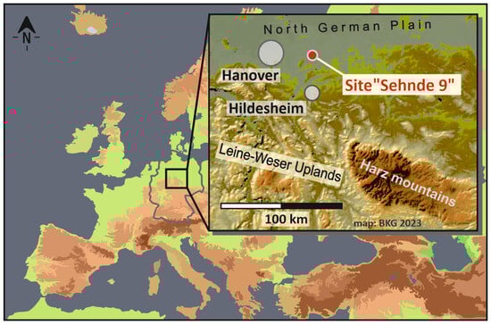
Figure 1.
Location of the Sehnde 9 site in Northern Central Europe.
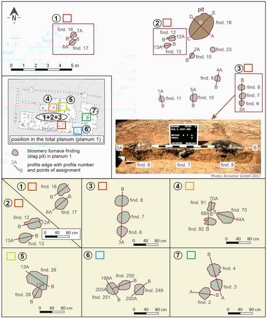
Figure 2.
Extract from the excavation plan from the Sehnde 9 site with grouped bloomery furnace findings.
Eighteen of the thirty-two bloomery furnace pits are situated in close proximity to each other (Figure 2). The topsoil layer was excavated by an excavator to a depth of around 30 to 40 cm until the underlying layer was exposed. Given that the excavation site is situated in an area that was recently utilized as a field, no in situ discoveries are anticipated within this plow horizon [1]. Considering this fact, it may be inferred that in certain instances, the findings just represent the deepest regions of funnel-shaped pits, suggesting that the furnace pits would have possessed a bigger width at the ground level of that time. Consequently, certain bloomery furnaces could not have been constructed simultaneously, as this would have resulted in overlap, given that the furnace wall was undoubtedly thickest at the base of the kiln shaft. This raises the inquiry of why the furnace pits are situated in close proximity, even if they were utilized sequentially, and why the explanation does not lie in efficient human ventilation by bellows across several simultaneous furnace operations.
1.2. Archaeological References and the Bloomery Furnace Process
Furnace shafts recovered from ancient findings in Central Europe are exceptionally rare. In northern Central Europe, two significant sites where remnants of furnace walls were discovered are Salzgitter-Lobmachtersen [3,4] and Scharmbeck (Harburg district) [5]. Fragments of two furnace shafts were discovered in Scharmbeck. A furnace shaft can be virtually entirely rebuilt, exemplifying a bloomery furnace shaft from the early Roman Period of Germania Magna [5,6] (Figure 3a). The furnace shaft includes a deep slag pit and a slag tapping furnace, standing roughly one meter in height, and presumably possesses four ventilation apertures near the base of the shaft. The internal diameter at the base of the shaft is 31.5 cm, however at the higher entrance, it is 22.5 cm. The wall’s thickness is around 5 cm at the base and about 2 cm at the apex. Consequently, the design and dimensions of an early historical bloomery furnace shaft have been acknowledged and employed as a prototype for constructing diverse experimental archaeological bloomery furnace shafts subsequent to its publication [7,8].
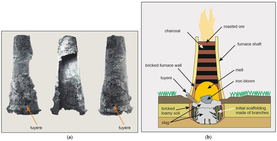
Figure 3.
(a) Almost completely assembled furnace shaft from Scharmbeck with a total height of about one meter from [5]; (b) schematic structure of a slag pit furnace according to [6].
The bloomery smelting technique from ancient and protohistoric periods is well-documented and has been extensively described in several sources [6,9,10,11]. Ultimately, comprehension of the subject depends on either geochemical and mineralogical analyses of archaeological smelting by-products or on conducting experimental smelting furnace operations [12,13,14]. Therefore, a concise explanation of the essential process phases will be provided here: It is probable that alternating strata of ore and charcoal were placed at the entrance of a bloomery furnace shaft, which was generally situated above a pit for collecting slag in the Inner Barbaricum (Figure 3b). Recent research demonstrates that air was injected through ventilation tuyeres positioned in the furnace wall just above ground level. Bellows were presumably employed. These enabled the furnace to attain temperatures of up to 1200 °C [15,16]. This resulted in the development of liquid slag phases [11,13].
Figure 4 delineates the procedures entailed in the preparation and implementation of a bloomery furnace journey.
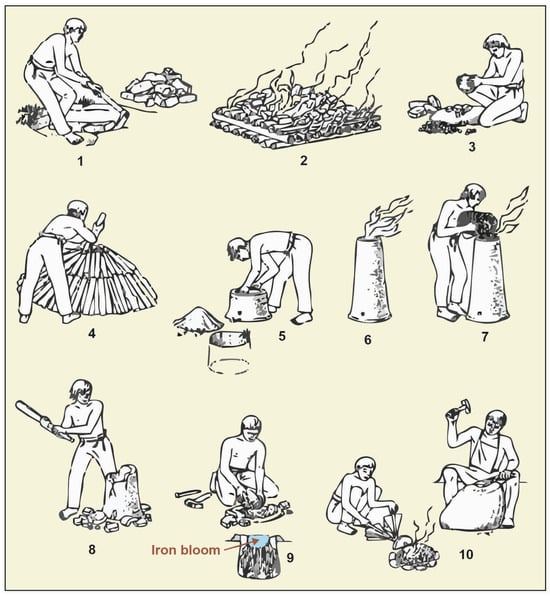
Figure 4.
Scheme of the steps in iron production in the Barbaricum during the early Roman Period from [17]—from ore to iron. (1) Ore extraction; (2) Ore roasting; (3) Crushing of the roasted ore; (4) Production of charcoal; (5) Construction of a bloomery furnace; (6,7) Furnace operation with alternating additions of ore and charcoal; (8) Destruction of the furnace shaft; (9,10) Extraction and further processing of the iron.
Crystallized solid iron originated from the molten material, presumably from constituents of solid ore, resulting in an iron bloom that could be extracted upon completion of the procedure [6,13]. Carbon monoxide and elemental carbon converted iron oxide into elemental iron. If the ores were not roasted prior to the bloomery furnace process, the conversion of iron oxide hydroxide into iron oxide would occur only within the bloomery furnace shaft. The expulsion of crystal water, including evaporation through the shaft aperture, would substantially lower the operational temperature of the bloomery furnace due to the requisite evaporation enthalpy, complicating the attainment of the minimum temperature of 1200 °C [6,15,17,18]. Current literature posits that the shaft of a bloomery furnace was dismantled at the conclusion of its operation to retrieve the iron bloom [17,19,20] (Figure 4).
1.3. Research Question and Design
During the bloomery furnace experiments XP 1 to XP 6, the furnace shaft was always destroyed, as this seemed to be the standard procedure (Figure 4). When planning the subsequent furnace runs as part of this work, a conscious effort was made to improve efficiency in order to save time and labour. The objective was to extract bloomery iron, primarily for the purpose of obtaining slag for geochemical investigations in a subsequent study. This led to the concept of use a shaft repeatedly. The term “multiple use” implies that a heavy shaft could not have been relocated significantly, notwithstanding the absence of any necessity related to relief or otherwise. It would be relocated a few decimetres and thereafter reused. This would create a pattern of slag pits, as evidenced by the archaeological complexes at the Sehnde 9 site in certain areas. This prompted the inquiry of whether the furnace shafts in early Roman Period Sehnde were potentially reused and only positioned over another furnace pit. This approach would eliminate the necessity of reconstructing a furnace shaft each time, and with three furnace cycles, would ultimately result in time savings of many hours to days. This approach, when applied to the entire smelting site, would significantly enhance the temporal efficiency of iron production.
Evidence of multi-use bloomery furnaces from the La Tène period in northern Central Europe exists, indicating that their shafts did not require destruction after a single operation. This is exemplified by the recently documented “Glienick” type from the Teltow region (Potsdam-Mittelmark district, Brandenburg) [21,22,23]. A substantial aperture was incorporated in the furnace chest for the extraction of the bloom, together with all slag and charcoal remnants, which could be resealed if required. Similar findings were obtained from the experimental furnace runs of [24]. The findings in Sehnde fundamentally differ from those in Teltow, indicating that a distinct approach of bloom recovery was employed in this instance. A model was constructed as a working hypothesis for tests XP 7 to XP 9, which may elucidate the patterns observed in the Sehnde set of findings (Figure 5): If the ventilation tuyeres are not incorporated into the furnace wall but are partially embedded in the ground beneath the shaft base, and if the slag pit is excavated deeper than normal in tests XP 1 to XP 6, then the entire process is shifted further down into the earth. This configuration renders the shaft independent of the underlying structural conditions. Consequently, it is portable, if it is sufficiently sturdy in construction. The region with the highest processing temperature is located beneath the ventilation tuyeres at the furnace shaft base, potentially safeguarding the shaft and enhancing its longevity. Subsequent to a smelting operation, the shaft might be effortlessly repositioned by rotation to facilitate access to the incandescent bloom. Given that the shaft has a mass of roughly 160 kg, with an average density of the building material (clay) estimated at 2 g/cm3 and a calculated wall volume of around 80 litres, it seems improbable that a shaft of this weight could have been transported over extensive distances. The substantial weight and the need to prevent transport damage to the material, which becomes increasingly brittle owing to heat, may have necessitated that the shaft, and thus the site of the subsequent kiln voyage, remained close to its initial position. It appears likely that excavating a new pit would need significantly less effort than building a new furnace shaft.
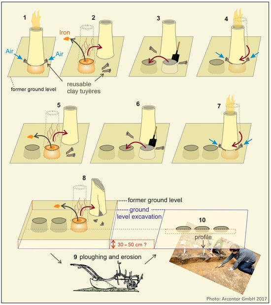
Figure 5.
Operational model of the repeatedly used furnace shafts of the “Sehnde” type using some of the findings from the Sehnde 9 site as a working basis for the experimental archaeological experiments XP 7 to XP 9.
This process cannot be perpetuated indefinitely, as a furnace shaft that grows progressively brittle with each smelting cannot consistently endure the temperature and mechanical forces. It is noteworthy that a maximum of three furnace operations with a moveable furnace shaft may have been feasible. Consequently, the experimental archaeological furnace operations XP 7 to XP 9 were not just intended to generate materials for elucidating archaeometallurgical inquiries. They additionally functioned, as previously noted, to examine the feasibility of numerous utilizations of the furnace shafts to enhance efficiency and consequently to evaluate the operational model (Figure 5).
2. Materials and Methods
“The study of metalworking remains one of the primary goals of archaeological science”, for which, in addition to archaeological, historical, and ethnographic sources, experimental replication is indispensable for understanding [25]. “Over the last decades, bloomery iron smelting has moved from the largely theoretical to the practical” [26]. “The combination of good archaeological evidence, giving the basic criteria to underpin the experiments, with the results of experiments then providing data for more informed archaeological interpretations gives a ‘virtuous circle’” [27]. In this study, the established and described methods of experimental iron smelting were applied in accordance with [25,26,27]. Twenty-five experimental trials of bloomery furnaces have been executed at the NAKUBI Grafhorn open-air museum in the Hanover district of Lower Saxony, Germany, with seven incorporated into this analysis. The tests are XP 7, XP 8, XP 9, XP 16, XP 19, XP 20, and XP 22 (named according to [27]). To do this, bloomery furnaces were reconstructed to closely align with the archaeological findings. The assessment of the excavation documents from the Sehnde 9 site indicates that a clay furnace shaft was constructed in alignment with other discoveries from the Roman Period in northern Central Europe (see to Section 1.2). The bloomery furnace from Salzgitter-Lobmachtersen utilized a clay encasement around a framework of rods during the shaft’s construction, which functioned as a support structure. This network is observable today in various impressions found in furnace walls [4]. Consequently, to enhance the stability of the furnace shaft in trials XP 7, XP 8, and XP 9, a support structure was initially fabricated using woven willow, linden, and maple rods (Figure 6A,B).
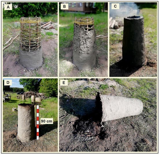
Figure 6.
Steps of furnace construction. (A,B): construction of the shaft around a support frame made of willow rods. (C): drying fire. (D): dried shaft without an underlying slag pit. (E): furnace shaft, tipped over the side.
A mixture of clay and straw was employed for the furnace walls to reduce cracking. This enabled the rapid building of a 90 cm high kiln shaft within a few hours, without necessitating a pause in construction for drying fires. The support scaffolding also contributed positively to this. The fire was ignited only after completion (Figure 6C,D). Subsequently, the kiln shaft needed to be relocated due to the absence of an excavated kiln pit (slag pit) during the construction phase. The shaft was inclined and positioned on the ground. This also functioned as an evaluation to ascertain whether the shaft could endure the resultant mechanical forces of the movement (Figure 6E). Excavating a slag pit prior to construction was feasible; however, it was not executed since falling construction material would have reduced the volume intended for the slag cake.
Locally sourced, previously roasted bog iron ore was utilized for the ore charging. The charcoal was produced from European oak.
Continuous ventilation was supplied by an electric fan with two separate tuyeres. Temperatures were recorded using an infrared thermometer BT-Meter 1500 (BTMETER, Zhuhai, China) via the ventilation tuyere in what was presumed to be the hottest section of the furnace
3. Results
3.1. Results of the Test Series and Adaption of the Initial Model
The test configuration was established in accordance with the operational model (Figure 4). Subsequent to the furnace run for test XP 7 (Figure 7A), the kiln shaft was to be tipped over marginally as intended and thereafter displaced laterally with a rotational motion around a support point at the base. The temperature of the outer surface of the furnace shaft varied from 120 °C at the base to 80 °C near the throat opening. The shaft could be safely touched while wearing leather hand protection. During the tilting procedure, it became evident that the friable material could not endure a rotational movement at a force of roughly 160 kg. Consequently, an impulsive choice was executed to entirely incline the shaft until it was horizontal (Figure 7B), what corresponds to the action taken post-drying fire subsequent to the shaft’s construction. The iron bloom might then be retrieved. The outline of the slag pit on the ground surface was significantly altered and expanded in diameter. This elucidates the impossibility of reinstalling the shaft in the original pit. Moreover, the process temperature resulted in the horizontal escape of crystal water and pore water from the substrate surrounding the slag pit several centimetres into the earth. This resulted in the substrate losing all cohesiveness, so impairing its capacity to support the furnace shaft in the same location again (Figure 7C). Consequently, the furnace shaft was advanced several centimetres, and a new slag pit, measuring 50 cm in depth, was excavated adjacent to the new location of the shaft base. The hole was subsequently filled with knots to reinforce the shaft, the two ventilation nozzles were fitted (Figure 7D), and the shaft was then raised to align it over the pit. The wall at the shaft base crumbled, resulting in a reduction of roughly 20 cm in the height of the furnace shaft (Figure 7E). Following the removal of the fragments, the furnace shaft, now truncated from the bottom, could be realigned, allowing for the execution of the second furnace run, test XP 8, utilizing the same shaft (Figure 7F). The originally 90 cm high furnace shaft now measured 70 cm; nevertheless, this height was not fully utilised for charging raw materials in test XP 8 (Figure 8A,B). The problem of soil pulverization surrounding the slag pit, which concurrently serves as the base for the furnace shaft, appears to have been recognized during that period. Consequently, the intentional lining of the slag pit with clay prior to the furnace operation may be viewed as an effort to enhance the durability of the slag pit, albeit for a single furnace run. Reference [25] documents multiple smelting locations in northern Central Europe, indicating the presence of clay liner in the slag pit. He asserts that the implementation of this strategy is not attributable to a specific furnace architecture, but rather to the individual, possibly even spontaneous, insight that certain stabilizing measures were essential. In tests XP 1 to XP 9, the slag pits were sometimes coated with clay and sometimes not. No differences in the effects were observed. This can be ascribed to the soil characteristics in the vicinity of the Grafhorn Open-Air Museum. While attempting to recline the furnace shaft of experiment XP 8 after the conclusion of a smelting operation, the shaft fractured into substantial parts (Figure 8D).
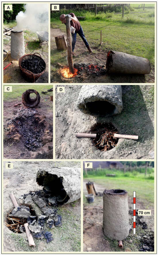
Figure 7.
Experimental archaeological experiment XP 7 to test a reusable shaft. (A): furnace run experiment XP 7. (B): compacting the iron bloom at the end of the XP 7 furnace run. (C): situation after removal of the iron bloom (XP 7). (D): prepared slag pit for experiment XP 8. (E): broken shaft base after the attempted righting of the shaft. (F): shortened furnace shaft for XP 8.
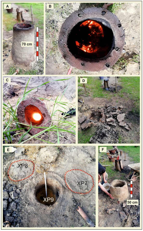
Figure 8.
Experimental archaeological trials XP 8 and XP 9 to test a reusable shaft (A): furnace run experiment XP 8. (B): view into the shaft opening XP 8. (C): view into the ventilation tuyere XP 8. (D): fragments of the broken shaft after XP 8. (E): prepared slag pit for experiment XP 9. (F): reassembled shaft fragments for XP.
However, it appeared more efficient and significantly quicker to rebuild the shaft out of the wall fragments using clay slurry rather than to build a completely new furnace shaft. Nevertheless, the shards had become so delicate that they could not be transported far; instead, they had to be reassembled on-site above a newly excavated slag pit (Figure 8E,F) for previously stated reasons. The kiln shaft, at 50 cm in height, remained adequate for the furnace (XP 9). At the conclusion of this experiment, the shaft was irretrievably damaged. These findings may elucidate the presence of a maximum of three, and occasionally only two, adjacent slag pits within the archaeological assemblages, a constraint attributed to the finite durability of the materials.
The working model (Figure 4) must subsequently be amended. The restriction to three slag pits in close proximity may stem from the observation that a furnace shaft deteriorates from the bottom and is typically rendered inoperative after its third utilization at most (Figure 9). The initial construction of a taller furnace shaft intended to incorporate extra ore and charcoal charges would likely have produced an excessively heavy structure, rendering it impractical.
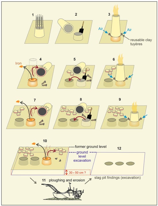
Figure 9.
Model of the multiple use and wear of furnace shafts of the “Sehnde” type as a result of the experimental archaeological experiments XP 7 to XP 9.
The XP 9 experiment, with a relatively low shaft height of only 50 cm, showed that this shaft height is indeed suitable with active ventilation, although the chimney effect alone, in the absence of active ventilation, would likely not have reached the required process temperature. Nonetheless, the shaft volume was adequate to hold sufficient feed material, enabling it to heat before to entering the melting zone and preventing it from descending unmelted into the slag pit.
An analysis of the cooled shaft fragments, which detached due to mechanical stress at the shaft base during movement, revealed that the wooden rod support structure was entirely charred or even cremated. Consequently, the efficacy of the initial reinforcement diminished, leading to increased susceptibility to fracture. Higher up, the rod weaving remained intact, composed of uncharred wood, and may potentially provide a stabilizing influence. This elucidates why shaft wear predominantly transpires in regions of elevated process temperatures, specifically in the basal area, hence constraining reusability based on a predetermined shaft height.
An excavation of the experimental archaeological results from tests XP 7 to XP 9, adhering to the protocols of the Lower Saxony State Office for Monument Preservation, which included the establishment of a subgrade and profile, revealed a pattern of findings analogous to those discovered during the archaeological excavation of the Sehnde 9 site (Figure 10). The slag pits evidently intersect at the current terrain surface; however, they are more distanced at greater depths, as indicated by the excavation subgrade level in Sehnde.
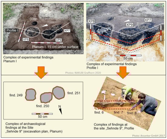
Figure 10.
Complex of findings from the experimental excavation of three bloomery furnace findings from experiments XP 7 to XP 9 on the NAKUBI Grafhorn site compared with complexes of findings from archaeological excavations at the Sehnde 9 site. White arrows: north arrows.
The repeated utilization of a bloomery furnace shaft in the establishment of new slag pits has not been documented in the literature for any archaeological era. The furnace shafts were either obliterated or opened and subsequently resealed on location. Consequently, this furnace type, consistent with the designation of the “Glienick” furnace type, will be called after the site of the discoveries that prompted its characterization, and will henceforth be referred to as the “Sehnde” furnace type.
3.2. Quality and Quantity of Subsequent Bloomery Furnace Operations Utilizing Reused Shafts
Despite the elevated raw material input and iron yield in the initial furnace cycle (XP 7) compared to the following two cycles (Table 1), the slag pit was never entirely filled with slag. The limitation of the filling mass was solely due to the scarcity of available raw materials. the scarcity of available raw materials. Consequently, theoretically, all three furnace cycles may have generated much greater yields. Clearly, in the context of active ventilation, it is the volume of the slag pit rather than the height of the furnace shaft that influences the outcome to some degree.

Table 1.
Information on ore and charcoal usage as well as iron yield of the experiments XP 7, XP 8 and XP 9.
Even though it can be assumed that the reaction time increases with the shaft height and this could have relevant consequences on the final yield, the relative yield of 0.077 kg of iron/kg of ore at XP 7 and 0.071 kg of iron/kg of ore at XP 8 and XP 9 remains approximately the same. The furnace shaft already serves as a reduction chamber, but not at its full height. The upper section of the furnace shaft can therefore simply be considered a container for the raw material feed. If the shaft height is shortened due to wear from below, the sections then serve as reaction chambers.
4. Discussion
4.1. Reasons for Wear of the Shaft Base and the Bloomery Furnace Finding Patterns
Thermal alteration, carbonization of the support structure, and the contribution of the furnace wall material to slag production substantially affect the degradation of the furnace wall [6,13,15,16]. For the Sehnde 9 site, based on the results of geochemical analyses of archaeological slags and raw ores, an average contribution of 16.5 mass percent from the furnace wall to the resulting slag of the smelting processes was determined [28]. Thus, the shaft base functions as sacrificial material.
The spacing of the individual bloomery furnace features at the Sehnde 9 site shows a certain regularity (Figure 2). This suggests that additional furnace runs using the same shaft were originally planned, but the shaft was too severely damaged during the first attempt. This also applies to the two-furnace arrangements (Figure 2). In this case, it can be assumed that the furnace shaft was permanently destroyed after the second furnace run.
4.2. Repetition of the Multiple Use of Furnace Shafts
For the XP 16, XP 19, XP 20, and XP 22 trials, a mesh-reinforced shaft was constructed. However, this shaft was initially only 60 cm high. Instead of being placed directly on the ground surface, the shaft was placed on a clay foundation that was deliberately intended as a wear-and-tear area (Figure 11). The aim was to determine whether this would significantly increase the number of reuses of the actual shaft. The quantitative data on raw material use and yield from the trials are presented in Table 2.
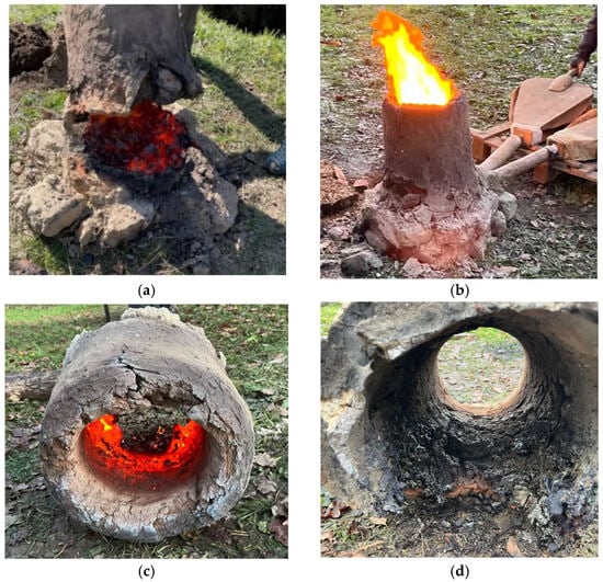
Figure 11.
Experimental bloomery furnace runs with the reused shaft: (a) XP 19; (b–d) XP 22.
Table 2.
Information on ore and charcoal usage as well as iron yield of the experiments XP 16, XP 19, XP 20 and XP 22. OCISC: oxidized clay iron stone concretions.
However, even in this series of tests, the furnace shaft finally broke after the fourth attempt. It was observed that the shaft lost wall material with each furnace run, which evidently became part of the melt. The number of reuses is evidently limited for both possible construction methods due to the same limiting factors (see Section 4.3). It remains unclear which method was used in ancient Sehnde, as there is no evidence of furnace wall remains. If the magnitudes of the ore quantities and iron yields do not appear directly comparable to those in the first test series (XP 7–XP 9), it is due to the fundamentally different ores of the individual experiments, as the experiments simultaneously examined further results for different research questions, presented in [28]. In XP 16, XP 19, XP 20, and XP 22, the slag pit was never completely filled. Here, too, the limiting factor was the amount of ore still available at the outcrop today, so theoretically a higher yield is conceivable.
4.3. Comparison of Similar Findings from Northern Central Europe
The bloomery furnace findings from the Zapfenbach Valley near Quedlinburg (Quedlinburg district, Saxony-Anhalt) also emerged in arrangements of two or three (Figure 12a and Figure 13). These were not as severely eroded as those in Sehnde. Therefore, even the areas of the slag pits, in which the furnace slag is primarily formed and which act as a lid covering the underlying flowing slag, are preserved. Nevertheless, it is conceivable that the technique of multiple furnaces was also used in the Zapfenbach Valley. The findings are comparable to those in Sehnde, even if the preservation conditions in Quedlinburg are considerably better. There are no findings from the site “B6n Quedlinburg” in the Zapfenbach Valley that would rule out the use of multiple furnaces of the “Sehnde” type [29].
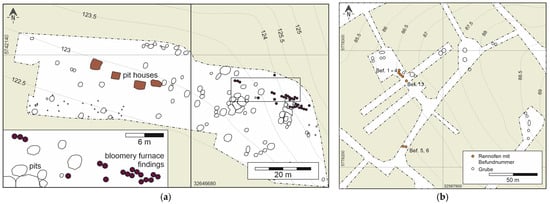
Figure 12.
Excerpts from excavation plans with grouped findings of bloomery furnaces from the early Roman Period in Northern Central Europe. (a) Quedlinburg “B6n” [29]; (b) Salzgitter “Fredenberg” [30].
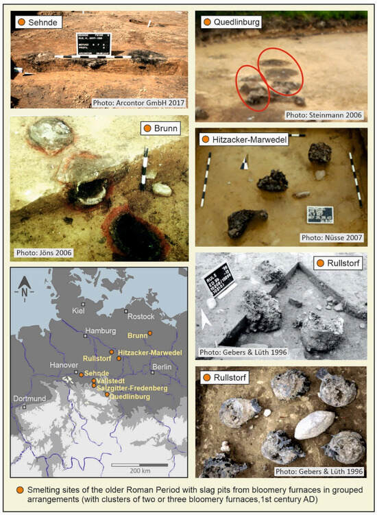
Figure 13.
Bloomery furnace findings in triple grouped arrangements of the early Roman Period in northern Central Europe. Sehnde [1], Quedlinburg [29], Brunn [31], Hitzacker-Marwedel [32], Rullstorf [33].
In Salzgitter-Fredenberg (Salzgitter district, Lower Saxony, Germany), bloomery furnace findings were also discovered in a grouped arrangement (Figure 12b). Since only exploratory sections were laid out here, only seven smelting furnaces have been discovered. It is assumed that additional smelting furnaces were also used here, whose remains have not yet been excavated.
Numerous other sites in northern Central Europe, whose smelting findings also date to the early Roman Imperial period, show the same striking cluster of bloomery furnace pits with up to three pits (Figure 13). All publications from the sites shown in Figure 13 mention that at least a significant portion of the bloomery furnace findings occur in groups of three [1,29,31,32,33]. It is possible that the cause of these patterns of findings lies in the use of bloomery furnaces of the “Sehnde” type. A systematic comparison with other sites is still pending. Possible connections regarding a cultural, economic, and technological context are extensively discussed in [34].
5. Conclusions
It has been experimentally demonstrated that bloomery furnace shafts can be used multiple times and thus represent a possible explanation for the grouped archaeological bloomery furnace findings of the early Roman Period in northern Central Europe. Experiments XP 7 to XP 9 also show that when using the same ore, the relative yield remains approximately constant despite the decreasing shaft height. In conjunction with a significant time gain of presumably several days, which was experimentally required for the respective new constructions of furnace shafts, this means an assumed increase in iron yield per unit of time. Even if the absolute yield in reuses should have been lower, the alternative would have been just a single smelting process within the same time. Multiple use, regardless of the possibility, means, in any case, an increase in the total yield within a given time span. The limitation on the frequency of reuse lies in the wear of the lower part of the shafts, which is likely to result from, among other things, the chemical processes in the interaction of the ore chemistry, the geochemical composition of the furnace wall and mechanical stresses.
A new furnace type “Sehnde” for the early Roman Period in the inner Barbaricum is suggested.
Author Contributions
Conceptualization, C.H. and F.K.; methodology, C.H., F.K. and M.S.; validation, C.H., F.K. and M.S.; investigation, C.H. and F.K.; resources, C.H., F.K. and M.S.; data curation, C.H.; writing—original draft preparation, C.H.; writing—review and editing, C.H. and M.S.; visualization, C.H.; supervision, M.S. All authors have read and agreed to the published version of the manuscript.
Funding
This research received no external funding.
Data Availability Statement
Data is contained within the article.
Conflicts of Interest
The authors declare no conflict of interest.
References
- Arcontor Projekt GmbH. Bericht zur Archäologischen Untersuchung vom 03.-11.05.2017 Und 10.07.-17.11.2017: Unveröffentlichte Grabungsdokumentation; Arcontor Projekt GmbH: Cremlingen, Germany, 2017. [Google Scholar]
- von Olberg, G.; Gemeinde. Germanische Altertumskunde Online GAO Database; Princeton University Library: Princeton, NJ, USA, 2010. [Google Scholar]
- Stelzer, G. Die germanische Siedlung und der Rennofen von Salzgitter-Lobmachtersen. Niedersächsisches Jahrb. Für Landesgesch. N. F. Z. Hist. Ver. Für Niedersachs. 1960, 29, 006–027. [Google Scholar]
- Osann, B. Rennstahlgewinnung in einer germanischen Siedlung beim heutigen Salzgitter-Lobmachtersen. Nachrichten Aus Niedersachs. Urgesch. NNU 1960, 29, 28–34. [Google Scholar]
- Wegewitz, W. Ein Rennfeuerofen aus einer Siedlung der älteren Römerzeit in Scharmbeck (Kreis Harburg). Nachrichten Aus Niedersachs. Urgesch. NNU 1957, 26, 3–25. [Google Scholar]
- Pleiner, R. Iron in Archaeology: The European Bloomery Smelters; Archeologický ústav AVČR: Praha, Czech Republic, 2000. [Google Scholar]
- Reepen, B.; Drexler, H.-J. Rennofenversuche Am Sachsenhof in Greven—Ein Erfahrungsbericht. In Experimentelle Archäologie in Europa. Bilanz 2004; Isensee, F., Ed.; Europäischen Vereinigung zur Förderung der Experimentellen Archäologie: Oldenburg, Germany, 2005; pp. 159–166. [Google Scholar]
- Paysen, A. Nachhaltige Energiewirtschaft? Universitätsbibliothek Kiel: Kiel, Germany, 2011. [Google Scholar]
- Joosten, I.; Jansen, J.B.H.; Kars, H. Geochemistry and the Past: Estimation of the Output of a Germanic Iron Production Site in The Netherlands. J. Geochem. Explor. 1998, 62, 129–137. [Google Scholar] [CrossRef]
- Yalcin, Ü. Zur Technologie der Eisenverhüttung. Arb.-Forschungsberichte Zur Sächs. Bodendenkmalpfl. 2000, 42, 307–316. [Google Scholar]
- Charlton, M.F.; Crew, P.; Rehren, T.; Shennan, S.J. Explaining the Evolution of Ironmaking Recipes—An Example from Northwest Wales. J. Anthropol. Archaeol. 2010, 29, 352–367. [Google Scholar] [CrossRef]
- Paynter, S. Regional Variations in Bloomery Smelting Slag of the Iron Age and Romano-British Periods. Archaeometry 2006, 48, 271–292. [Google Scholar] [CrossRef]
- Kronz, A.; Eggers, T. Archäometallurgische Untersuchungen eisenzeitlicher Funde aus dem Hügelgräberfeld Hillesheim, Kreis Daun. Trier. Z. Für Gesch. Kunst Trier. Landes Seiner Nachbargeb. 2001, 64, 69–109. [Google Scholar]
- Paynter, S.; Crew, P.; Blakelock, E.; Hatton, G. Spinel-Rich Slag and Slag Inclusions from a Bloomery Smelting and Smithing Experiment with a Sideritic Ore. Hist. Metall. 2021, 49, 126–143. [Google Scholar]
- Straube, H. Ferrum Noricum und Die Stadt auf dem Magdalensberg; Springer: Vienna, Austria, 1996. [Google Scholar] [CrossRef]
- Cavallini, M. Thermodynamics Applied to Iron Smelting Techniques. Appl. Phys. A 2013, 113, 1049–1053. [Google Scholar] [CrossRef]
- Jöns, H. Eisengewinnung im norddeutschen Flachland. Archäol. Dtschl. Sonderh. 1993, 1, 63–69. [Google Scholar]
- Ganzelewski, M. Archäometallurgische Untersuchungen zur frühen Verhüttung von Raseneisenerzen am Kammberg bei Joldelund, Kreis Nordfriesland. In Frühe Eisengewinnung in Joldelund, Kr. Nordfriesland: Ein Beitrag zur Siedlungs- und Technikgeschichte Schleswig-Holstein. 2: Naturwissenschatliche Untersuchungen zur Metallurgie- und Vegetationsgeschichte; Haffner, A., Jöns, H., Reichstein, J., Eds.; Universitätsforschungen zur prähistorischen Archäologie; Habelt: Bonn, Germany, 2000; Volume 59, pp. 3–100. [Google Scholar]
- Häßler, H.-J.; Berger, F. Ur- Und Frühgeschichte in Niedersachsen; Nikol: Hamburg, Germany, 2002. [Google Scholar]
- Behre, K.-E. Landschaftsgeschichte Norddeutschlands: Umwelt und Siedlung von der Steinzeit bis zur Gegenwart; Wachholtz: Neumünster, Germany, 2008. [Google Scholar]
- Brumlich, M.; Meyer, M. Ofenanlagen der Vorrömischen Eisenzeit bei Waltersdorf, Landkreis Dahme-Spreewald: Ein Beitrag zur Frühen Eisenverhüttung; Arbeitsberichte zur Bodendenkmalpflege in Brandenburg: Brandenburg, Germany, 2004; pp. 167–196. [Google Scholar]
- Brumlich, M.; Meyer, M.; Lychatz, B. Archäologische und archäometallurgische Untersuchungen zur latènezeitlichen Eisenverhüttung im Nördlichen Mitteleuropa. Praehist. Z. 2013, 87, 433–473. [Google Scholar] [CrossRef]
- Brumlich, M. Frühe Eisenverhüttung Bei Glienick; Berliner Archäologische Forschungen; Verlag Marie Leidorf GmbH: Rahden, Germany, 2018; Volume Band 17. [Google Scholar]
- Benvenuti, M.; Orlando, A.; Borrini, D.; Chiarantini, L.; Costagliola, P.; Mazzotta, C.; Rimondi, V. Experimental Smelting of Iron Ores from Elba Island (Tuscany, Italy): Results and Implications for the Reconstruction of Ancient Metallurgical Processes and Iron Provenance. J. Archaeol. Sci. 2016, 70, 1–14. [Google Scholar] [CrossRef]
- Nikulka, F. Frühe Eisenerzverhüttung und ihr experimenteller Nachvollzug: Eine Analyse bisheriger Versuche. Archäol. Mitteilungen Aus Nordwestdtschl. Beih. 1994, 8, 255–310. [Google Scholar]
- Markewitz, D. Standardized Reporting of Experimental Iron Smelting—A Modest (?) Proposal. EXARC J. 2021, 1, 1–25. Available online: https://exarc.net/ark:/88735/10559 (accessed on 22 September 2025).
- Crew, P.; Crew, S. Twenty-Five Years of Bloomery Experiments: Perspectives and Prospects. In Accidental and Experimental Archaeometallurgy; Historical Metallurgy Society: Tunbridge Wells, UK, 2013; pp. 25–50. [Google Scholar]
- Helmreich, C.; Kobbe, F.; Kierdorf, H.; Kierdorf, U.; Sauerwein, M. Observations Suggesting the Use of Manganese-Rich Oxidized Clay Iron Stone Concretions for Iron Production During the Early Roman Imperial Period in the Inner Barbaricum—A Multi-Method Approach. Minerals 2025, 15, 1274. [Google Scholar] [CrossRef]
- Steinmann, C.V. Eine Rennofenanlage aus der Zeit um Christi Geburt. In Archäologie XXL: Archäologie an der B 6n im Landkreis Quedlinburg; Meller, H., Ed.; Archäologie in Sachsen-Anhalt Sonderband; Landesamt für Denkmalpflege und Archäologie Sachsen-Anhalt—Landesmuseum für Vorgeschichte: Halle (Saale), Germany, 2006; Volume 4, pp. 157–162. [Google Scholar]
- Kriete, C. Geochemische Untersuchungen der Rennfeuerschlacken aus dem Siedlungsgebiet der vorrömischen Eisenzeit und Älteren Römischen Kaiserzeit von Salzgitter-Fredenberg im Hinblick auf die Herkunft der verwendeten Erze. Nachrichten Aus Niedersachs. Urgesch. NNU 2009, 78, 37–56. [Google Scholar]
- Jöns, H. Zum Beginn der Eisenverhüttung Im Norden—Die Rennfeueröfen von Groß Siemz, Vietow und Brunn. In Die Autobahn A20—Norddeutschlands Längste Ausgrabung: Archäologische Forschungen auf der Trasse Zwischen Lübeck und Stettin; Archäologisches Landesmuseum und Landesamt für Bodendenkmalpflege Mecklenburg-Vorpommern: Schwerin, Germany, 2006; pp. 97–100. [Google Scholar]
- Nüsse, H.-J. Geomagnetische Prospektion und archäologische Untersuchungen bei den Fürstengräbern von Marwedel, Ldkr. Lüchow-Dannenberg—Ein Zwischenbericht. Praehist. Z. 2007, 82, 85–113. [Google Scholar] [CrossRef]
- Gebers, W.; Lüth, F. Materialhefte zur Ur- und Frühgeschichte Niedersachsens Reihe A; Hahn: Rahden/Westfalen, Germany; Hannover, Germany, 1996. [Google Scholar]
- Helmreich, C.; Kobbe, F.; Sauerwein, M. Manganese-Rich Oxidised Clay Iron Stone Concretions Used as Iron Ore in a New Furnace Type during the Early Roman Imperial Period in the Inner Barbaricum—An Expression of Knowledge Transfer? Institute of Geography, University of Hildesheim: Hildesheim, Germany, 2025; manuscript in preparation. [Google Scholar]
Disclaimer/Publisher’s Note: The statements, opinions and data contained in all publications are solely those of the individual author(s) and contributor(s) and not of MDPI and/or the editor(s). MDPI and/or the editor(s) disclaim responsibility for any injury to people or property resulting from any ideas, methods, instructions or products referred to in the content. |
© 2025 by the authors. Licensee MDPI, Basel, Switzerland. This article is an open access article distributed under the terms and conditions of the Creative Commons Attribution (CC BY) license (https://creativecommons.org/licenses/by/4.0/).