Abstract
This paper presents the first insight into how Almada Negreiros, a key artist of the first generation of modernism in Portugal, created his mural painting masterpiece in the maritime station of Rocha do Conde de Óbidos in Lisbon. This set of six monumental mural paintings dates from 1946 to 1949 and is considered Almada’s artistic epitome. As part of the ALMADA project: Unveiling the mural painting art of Almada Negreiros, the murals are being analyzed from a technical and material perspective to understand his modus operandi and the material used. This is the first study of this nature carried out on site and in the laboratory using standard and more advanced imaging, non-invasive analysis, and microanalysis techniques. This article reports the results obtained with visual examination, technical photography in visible (Vis), visible raking (Vis-Rak), complemented by 2D and 3D optical microscopy (OM), scanning electron microscopy with energy-dispersive spectrometry (SEM-EDS), and Fourier transform infrared micro-spectroscopy (µ-FTIR) of the paint layers. The results show the similarities, differences, and technical difficulties that the painter may have had when working on the first, third, and presumably last mural to be painted. Vis-Rak light images were particularly useful in providing a clear idea of how the work progressed from top to bottom through large sections of plaster made with lime mortars. It also revealed an innovative pounced technique used by Almada Negreiros to transfer the drawings in full scale to the walls. Other technical characteristics highlighted by the analytical setup are the use of textured, opaque, and transparent paint layers. The structure of the paintings does not follow a rigid build-up from light to dark, showing that the artist freely adapted according to the motif represented. As far as the colour palette is concerned, Almada masterfully uses primary and complementary colours made with Fe-based pigments and with synthetic ultramarine blue, cadmium pigments, and emerald green.
1. Introduction
Almada Negreiros was one of the leading figures in Portuguese art and culture in the first half of the 20th century. With a career spanning almost 60 years, he belongs to the first generation of modernism in Portugal and is the author of a vast artistic oeuvre in distinct types of materials []. Between 1938 and 1956, he painted five sets of mural paintings in the city of Lisbon that are today considered masterpieces of modern art and which have been studied since 2021 from a technical, material, and diagnostic point of view as part of a transdisciplinary project ALMADA_Unveiling the mural painting art of Almada Negreiros [,,,,]. Among the works under study, the mural paintings painted in 1949 at the maritime station of Rocha do Conde de Óbidos stand out not only for their artistic and historical importance but also for the caused controversy before and after they were realised []. This set of paintings, made up of six monumental murals, is the most paradigmatic and challenging case study of the project (Figure 1). Paradigmatic because it is Almada’s greatest artistic achievement as a muralist painter, but also paradigmatic in terms of the materials and techniques used by the artist. These paintings, like the other sets, are written down only as frescoes in the official commission documents, but it is unlikely that they were entirely created using this technique due to their characteristics, which raises a number of unanswered questions for technical art history and conservation–restoration.
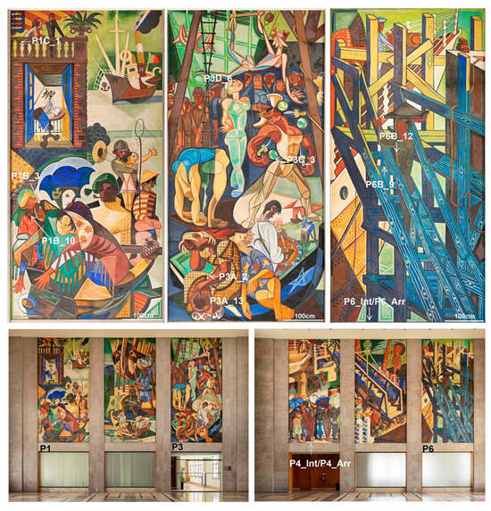
Figure 1.
Overview of the mural paintings in the east and west of walls of the main shipping hall and of the murals named P1, P3, and P6, which were presumably the first, third, and last to be painted. The indication of the sampling location discussed in this paper is given in the three murals. The letters in the samples reference the name of the painting (P) and the different areas analysed (A, B, C, and D). Photos by M. Ribeiro 2022.
Almada Negreiros was a curious and experimental self-taught artist. The only records about his procedure on the walls of the maritime station are given by his wife, Sarah Affonso, who was a painter herself and helped him with the preparatory drawings []. But no details about the way he painted are known, and it is up to Heritage Science to try now to understand how he did it, using a multi-analytical approach. In 2022, an analytical campaign was made on this set of paintings, and the first results of the preliminary diagnostic survey were published in September 2023 []. At that time, the author’s concern was to identify the main decay phenomena present and their sources. Now, the intent is to reveal for the first time the various stages of the making of these murals, from the laying of the mortar to the paint execution, by using imaging techniques and on-site non-invasive analysis followed by microanalytical techniques in the laboratory.
Technical and material studies of mural paintings produced in the first half of the 20th century are still an unexplored field of research. The Industrial Revolution and advances in the chemical dyeing and painting industry from the 19th century onwards introduced new materials (such as Portland cement, acrylic, vinyl, and silicate-based paints) and paved new ways for mural painters to express their art on walls [,,,,]. All over the world, artists ceased to limit themselves to the traditional methods of fresco and secco and started experimenting with new painting techniques and synthetic colours [,,]. One of the most striking and well-known examples is Alvara Sequeiros’ mural America Tropical, done in 1932 in downtown Los Angeles (USA) by using a modified fresco technique on cement with a variety of modern tools [].
In Portugal, Almada Negreiros, although considered a fresco revivalist, was also experimenting, as shown by the discovery of red and yellow cadmium pigments and the green organo-synthetic pigment PG8, in his fresco production of 1939 and 1945 [,,]. In the set of paintings realised in 1949 at the maritime station of Rocha do Conde de Óbidos, he seems to have taken a step forward. This paper focuses on the scientific survey carried out on the six murals using visible and raking light examinations with further imaging and analytical instrumentation on the specific paintings named P1, P3, and P6 (Figure 1). These murals are supposedly the first, the third, and the last to be painted, hinting at how the work evolved. An in-depth study of the colour palette and organic materials present in the paint layers is beyond the scope of this paper and will be the subject of the second part of the research.
The Paintings Commission—An Historical Background
The six paintings located in the main departure hall on the first floor of the maritime station of Rocha do Conde de Óbidos are organised in two triptychs (Figure 1). On the west side of the room, the murals are dated 1946–1949, and on the opposite side, 1947–1949 (Figure 1). These dates are not indicative of the time it took Almada to paint them but rather of how the whole administrative process unfolded. Almada Negreiros only signed the contract on 17 February 1947 and began painting in the hall in 1949, after more than two years of preparatory work in his studio [,]. By then, the maritime station had already been inaugurated, and temporary plasters had been put on both walls []. These plasters were supposedly removed so that Almada Negreiros could paint the six murals measuring 7.80 m × 3.80 m. Using the demanding fresco technique, one would believe that the paintings had taken the eight months foreseen in the timetable set by the artist in December 1948 []. But it was Almada himself, in an interview with a newspaper [Diário de Lisboa] in 1950, who revealed that it took him three years to learn the fresco technique, but only 29 days to do this painting set, sometimes working 10 h a day []. This remarkable piece of information is particularly relevant for understanding the work performed if we consider that Almada painted alone, occasionally with the help of an assistant on site [,,].
The scenes depicted on the walls, in a cubism style inspiration, are the everyday life activities of Lisbon’s riverside and the immigrants’ departure. It must be noted that Almada Negreiros was working under a dictatorial regime that favoured the paintings of the heroes of nationalism [,,]. In these murals, he dared to be challenging and provocative by portraying the working classes, poverty, minorities, and emigration. Not surprisingly, the murals highly displeased the official authorities and were threatened with destruction after completion []. Only through the intervention of high-ranked influential figures from the cultural heritage at the time were the paintings spared and can today be appreciated.
2. Materials and Methods
The mural paintings were analysed in situ in 2022, using technical photography and non-invasive analytical techniques. The following text presents only the analytical setup and method conducted for the results discussed in this article.
2.1. In Situ Analysis
Visual examination and imaging were the first tasks to be performed on site. Technical photography included visible (Vis) and 360° visible raking light (Vis-RAK), near-infrared (NIR), and ultraviolet fluorescence induced in the visible range (UVF). The goal was to gather information about technical and material features and try to differentiate between the original and past intervention materials. The paintings were restored two times, in 1971 and 1979, with adhesives, such as PVA and Paraloid, and unknown retouching materials (oils, most likely).
Visible raking light photography was carried out at 15–20° angle from the paint surface, from 8 different directions, in order to obtain as much information as possible about the plastering work and paint execution. In total, 900 images were acquired and analysed, making it possible to map the plaster patches on the paintings P1, P3, and P6 and identify the techniques used by Almada to transfer the composition to the walls.
A Nikon D3200 24 MPx digital single lens reflex camera (Nikon Corporation, Tokyo, Japan) with an objective Nikkor 18–55 mm f:3.5–5.6 GIL ED (Nikon Corporation, Tokyo, Japan) was used for photography in the Vis, VIS-RAK, and UVF range. NIR Photography was made with a Nikon D3100 14.2 MPx camera (Nikon Corporation, Tokyo, Japan), modified for full spectrum (UV-VIS-IR) with the high pass filters 780, 850, and 1000 nm to ascertain the presence of IR absorbent materials that could have been used in underdrawings. Halogen lamps 1000 W-230 V D58525 (OSRAM GmbH, Augsburg, Germany) were used as light sources for both Vis and NIR photography. Natural daylight source from the windows nearby was also used for preliminary total and macro surveys of the painted surfaces with a Samsung Galaxy A52 (Samsung Electronics Co. Ltd., Suwon, South Korea) and a Canon EOS800D (Canon Inc., Tokyo, Japan), with a Sigma DC 17–70 mm 1:2.8–4 macro HSM lens (Canon Inc., Tokyo, Japan). For UV-induced fluorescence in the visible range imaging, we used a Labino®MPXL UV PS135 light (35 W PS135UV Midlight 230 V; Labino AB, Vallentuna, Sweden), with a UV filter included (310–400 mm and a peak at 365 mm), a midlight distribution angle of 20°, and a start-up time of full power after 5–15 s. The images were acquired in jpeg and in raw format with target QPCard101 for white balance. AIC PhD colour chart was also used to calibrate UVF images.
Imaging techniques were complemented by handheld optical microscopy (h-OM). Portable optical microscopy was performed with two handheld digital microscopes (Dino-Lite Digital Microscopes Premier AD3713TB and PRO AM413T-FVW; AnMo Electronics Corporation, New Taipei City, Taiwan) to explore optical properties and details of the paint layers (e.g., textures, pigments size, morphology, amount, and mixtures of pigments).
2.2. Micro-Sampling and Laboratorial Analytical Setup
With the information gathered by the non-invasive campaign, areas of original paint layers were selected for micro-sampling, stratigraphic analysis, and more in-depth technical and material characterisation, which was not possible with non-invasive analysis alone. Figure 1 shows the sampling location of the thirteen samples discussed in this paper. Most of the paint layers, with less than 0.5 mm in size, were collected near micro fissures, lacunae, or holes left by the method used to transfer the drawings into the walls. The paint microsamples were taken from the murals P1, P3, and P6, and the samples for mortar analysis from P3 and P6, except for P4_Int and P4_Arr that came from mural P4 due to the presence of larger and deeper lacunae at its edge that allowed for scraping the two layers of plaster easily. In mural P1, the lacunae were not deep enough, and the upper white layer of mortar was visually the same as in P3. In order to limit the sampling, it was decided to only take a sample from P3, which could also be used as a cross-section for other research purposes.
Paint layers collected were analysed as micro-fragments, without any kind of preparation, and as cross-sections, for stratigraphic and SEM-EDS analysis. For cross-sections, the micro-fragments were embedded in epoxy resin (Epofix, Struers, Ballerup, Denmark) and polished with different Micro-Mesh sanding sheets (GC Abrasives Ltd., Darlington, UK).
Optical microscopy (OM) of the micro-fragments was carried out with an HRX01 (Hirox, Tokyo, Japan) 3D digital microscope. The images shown in this paper were taken with the fragments from the front or in profile. For the cross-sections embedded in resin, the observations and photographic documentation were made with a dark field microscope DM2500M (Leica Microsystems, Mannheim, Germany) mounted, with reflective, visible light in dark field mode and ultraviolet radiation at 200× and 500×. Observations under UV radiation required the use of a high-pressure burner 103 W/2 UV lamp and an excitation pass band filter of 340–380 nm, a dichromatic mirror with 400 nm, and a suppression filter Lp425, size K coupled. The photographic documentation was obtained with a DFC290HD digital camera (Leica Microsystems, Mannheim, Germany).
Further material characterisation was performed with a variable pressure scanning electron microscope Hitachi S-3700N (Hitachi High-Technologies Corporation, Tokyo, Japan) in coupled with a Bruker XFlash 5010 (Bruker Nano GmbH, Berlin, Germany) Silicon Drift Detector energy-dispersive X-ray spectrometer (SEM-EDS). The resolution of the EDS detector is 123 eV at the Mn Kα line energy. SEM imaging was performed in the backscattered electron (BSE) mode. In order to collect X-ray emissions from heavier elements like Pb, an acceleration voltage of 20 kV was chosen for the analyses. Samples were analysed at a chamber pressure of 40 Pa, avoiding coating the samples. Element point/area analysis and elemental map distribution were made on the samples. The EDS tasks and the semi-quantification obtained were achieved through the Bruker (Bruker Nano GmbH, Berlin, Germany) ESPRIT compact software package (version 2.3.1.1019).
The plasters and the pigments characterisation were complemented with X-ray diffraction (XRD) and by micro-Fourier transform infrared micro-spectroscopy (µ-FTIR). X-ray diffraction analyses of the plasters were performed on a D8 Discover (Bruker) diffractometer with Cu Kα radiation. The diffraction patterns were collected from 3° to 75° 2θ and a time per step of 1 s with a working voltage and current of 40 kV and 40 mA, respectively. For the identification of organic materials, the paint layers were pre-screened using micro-Fourier transform infrared spectroscopy (µ-FTIR). For these analyses, a Thermo Nicolet Nexus 670 FTIR spectrometer was used, coupled with a Continuum IR microscope (Nicolet Instrument Corporation, Waltham, MA, USA). FTIR spectra were collected in transmission mode using the compression diamond Spectra-TechSample Plan cell. Each FTIR spectrum is the average of 254 scans collected at 4 cm−1 resolution in the region from 4000 cm−1 to 650 cm−1. No spectral processing other than the removal of the carbon dioxide bands was performed. The identification of the chemical compounds was made through the comparison of the samples’ spectra with reference FTIR spectra from the Thermo Scientific spectral libraries Coatings Technology, Industrial Coatings, Hummel Polymer and Additives, and bibliographic references [,,,,,,,,,,,,,]. The spectra were interpreted with Omnic 8.0. Termo Scientific (Nicolet Instrument Corporation, Waltham, MA, USA).
3. Results and Discussion
3.1. Laying out and Composition of the Plasters
In the contract signed by Almada, no information is given about the plastering work []. Unlike the earlier paint commission, Almada’s only obligation at the Rocha do Conde de Óbidos maritime station was to accompany the masons’ work to ensure that it was carried out properly []. In a fresco painting, daily sections (or patches) of plaster made with lime-based mortars are usually placed for the artist to paint while the surface of the mortar is still damp. This was no easy feat, and any defect in the materials or method used could compromise the final work []. Figure 2 shows the number and the location of the patches of plaster found by Vis and Vis-Rak light in the murals P1, P3 and P6. The number of patches appears to vary with the complexity of the decoration, being higher on P1 and P3, which had more figures and decorative details to paint (Figure 1 and Figure 2). Vis-Rak highlights the joining areas between the different plaster sections, and it can be perceived that each new layer of plaster stops along the edge and leans against the previous one rather than overlapping it. Sometimes, the joins between the different patches are well disguised and covered with thick paint layers, making them difficult to detect.
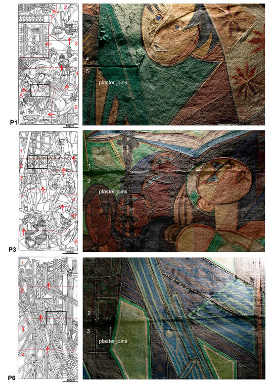
Figure 2.
On the right, mapping showing the location, the number, and the laying order of the plasters in P1, P3, and P6. The work proceeded from top to bottom and from left to right as indicated by the number and arrows. The dashed lines indicate the areas where the joins are not clearly visible by Vis-Rak. On the right, detailed images by Vis-Rak of the plaster joins showing the method of leaning the mortars against each other (photos by M. Ribeiro 2022; drawings by K. Rix/M. Gil 2022/24).
The shape of the patches of plaster also varies within and between the murals (Figure 2). On P1, horizontal and vertical plaster joins are visible, while on P3 and P6, only horizontal joins are found, suggesting the presence of what is known as giornata and pontata. These are two Italian terms commonly used in technical studies of mural paintings to appoint two types of working methodologies [].
In the case of pontata (pl. pontate), the only visible plaster joins are horizontal because the entire painted surface corresponds to one story of the scaffolding used. Since the plaster is applied all at once, the paintings may or may not be executed using the fresco technique, depending on the size of the pontata and the number of painters present on site. On the other hand, the use of giornata (pl. giornate) implies proceeding with smaller working areas, which historically, was the procedure most commonly adopted in large-scale fresco paintings to ensure that the pigments were applied to a damp plaster surface [,,,]. In such cases, vertical and horizontal joins are observed, with the number depending on the complexity and importance of the motifs depicted.
In the paintings from the maritime station of Rocha do Conde de Óbidos, the distinction between the two methodologies is not always straightforward due to the position, shape, and dimensions of the mortar sections (Figure 2). In the detailed analysis of the three murals, only in P6 is it clear that Almada proceeded by pontate, with each painted section corresponding to a story of the scaffolding. In P3, he seems to have used both types, although only horizontal joins are seen, and in P1, most of the mortar sections are unusually large for giornate. In this painting, some sections have more than 2 m × 1.5 m and have certainly surpassed a story of scaffolding (for example, the patch n°1, Figure 2).
Painting unusually large surfaces had already been reported in an earlier mural painted by Almada in 1939 in Lisbon []. But there, most of the paint layers are transparent or semi-transparent and were laid down at true and lime fresco. Here, most of the paint layers are quite opaque and sometimes thick and glossy, which has raised doubts about the painting techniques used.
Another unusual feature of the plasterwork observed is the fact that the edges of the plaster sections do not follow the outline of the figures depicted but cross through them in several places, even on the faces in P1 and P3 (Figure 2). In a secco painting, this would not be a problem, but in a fresco, where the colours can be very different once dried, it was a risk and required Almada to make an extra effort not only to match the colours but to disguise, if needed, any visible colour differences.
The marks of the instruments used to lay the mortars and smooth the surface can only be clearly seen by Vis-Rak on one of the larger sections of the upper part of P1 (Figure 3). On the rest of the surface and on the other murals, depressions can mainly be seen, which may have been caused by irregularities in the underlying masonry and the pressure exerted on the damp surface when the full-scale drawing sheets were transferred to the walls. Figure 3 shows a detailed image by Vis-Rak of the patch n°2 in P1. This patch with intense tool marks was placed on Almada’s second day of work at the maritime station and may indicate a defect that occurred during the drying of the mortar. Several large shrinkage cracks are clearly visible in this area, suggesting that there may have been some deficiency in the preparation and/or placement of the plaster. It is possible that Almada noticed the phenomenon during the course of painting—it should be noted that he could work up to 10 h a day—and tried to remedy it by further compressing the mortar with a float to save that day’s work. This would explain why this situation only occurred once in the full set of paintings.
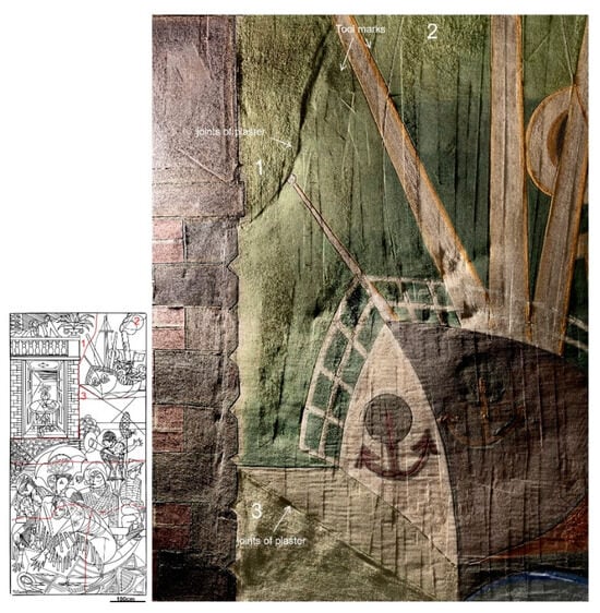
Figure 3.
On the left, location of the plaster patches observed in mural P1. Patch n°2 is in the top left corner. On the right, details in Vis-Rak of patch n°2 and adjacent areas of patches n°1 and n°3, showing the intense presence of tool marks on the former when compared to the surface of the other two. The marks were made by repeated pressure movements exerted vertically, presumably after the painting was done, as evidenced by the differences in the texture of the paint on the green background and on the mast of the boat (photo by M. Ribeiro, drawing by K. Rix 2022).
Regarding the composition of the plasters used in this set of paintings, through the lacunae at the base of the murals, it is sometimes possible to distinguish two layers of plaster (Figure 4a–c). The top layer is white and corresponds to the aforementioned mortar laid down for painting, while the inner layer is brownish and corresponds to the mortar normally applied to even out the surface of the wall. Unfortunately, the small size and depth of the lacunae make it impossible to measure the thickness of the inner layer of mortar; the top layer varies between 0.5 cm and 0.8 cm. Both layers of plasters are typical of fresco paintings and are generally referred to by their Italian names, arricio and intonaco.
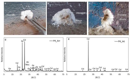
Figure 4.
Above, details of the sampling location of samples P3A_13 (a), P4_Int and P4_Arr (b), and P6_Int and P6_Arr (c) collected from lacunae of approximately 1.5 to 3 cm long at the edges of P3, P4, and P6. Below, diffractograms of P4_Arr (d) and P4_Int (e), representative of the four powdered mortars samples analysed by XRD.
XRD and SEM-EDS data from samples collected from P3, P4, and P6 are summarised in Table 1 and in Figure 4 and Figure 5. The results confirm that both plasters are made of calcium-based mortars. The two samples of arricio analysed by XRD are identical in terms of their mineralogical composition. Both consist of calcite with siliceous aggregates and potassic and sodic feldspars (microcline and albite) (Table 1, Figure 4d). Gypsum was only detected in P4_Arr in a small amount and may be present due to water infiltration. The presence of calcite is related to the use of calcitic aerial lime as a binder.

Table 1.
Summary of XRD and SEM-EDS results of the samples collected for plaster analysis at P3, P4, and P6.
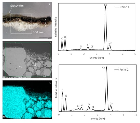
Figure 5.
On the left, from top to bottom; (a) P3A_13 cross-section in MO-Vis at 200×, indicating the three visible layers (1 is the intonaco, 2 and 3 are paint layers); (b) SEM backscattered image; and (c) SEM-EDS elemental distribution map of calcium showing the widespread presence and quantity of this element in the intonaco. On the right, SEM-EDS analysis of the intonaco aggregates and matrix. The results of the point analyses 1 and 2 (marked as *1 and *2 in the backscattered image) are given in Table 1.
On the other hand, the two samples of intonaco are essentially composed of calcite (Table 1, Figure 4e). SEM-EDS analysis of the intonaco of the P3A_13 cross-section also shows heterogeneous fragments of crushed carbonates around 400 µm to 50 µm long embedded in a Ca matrix (Figure 5). This material was used as a binder and as an aggregate, which explains the white colour observed in the lacunae. The quartz detected by XRD in sample P4_Int is associated with siliceous aggregates (sands). No gypsum was found in the two samples of intonaco analysed by XRD (Table 1).
3.2. Transferring the Composition to the Wall
The way Almada Negreiros transferred most of the full-scale drawings to the walls was quite innovative and, as far as the authors know, had never been reported before. P1 is particularly interesting in this respect, as Almada changed the technique of transposing the lines of the composition halfway through the work. In the upper part of this mural, there are incised lines, while from the lower half onwards, he changed his mind and used a new version of a technique known as poncif.
Traditionally, the poncif (or pounced drawing) technique involves making a series of small holes with a pointed instrument through the drawing executed on a piece of paper so that it can be reproduced on the wall by tapping with a gauze sachet filled with charcoal, or other powder pigments. The pigment passes through the holes made by a needle and is deposited on the surface of the intonaco []. Pounced drawing was one of the methods used by Almada, and it was usually followed by incisions made on top with the handle of the brush to link the dots together [,]. In the upper part of P1, there are still traces of such black dots. On the bottom half onwards, and on the remaining painted murals, Almada has pierced the paper with the drawings directly in the fresh mortar, leaving the holes imprinted on the surface. Figure 6a,b shows, by Vis-Rak, the two types of techniques used, and in Figure 6c, the detail in Vis of the imprinted holes, circa 3 mm apart, strongly suggesting that a round-tipped instrument was used for the purpose. By Vis-raking light, a slight rounded groove linking the holes can also be noticed, caused by the pressure exerted to pierce the drawings through the paper on the wet plaster (Figure 6c and Figure 7a,c).
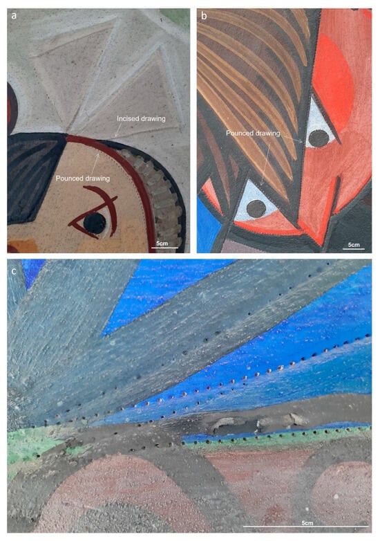
Figure 6.
Detailed images in Vis of the incised lines (a) and of pounced drawings (b,c) used by Almada to transfer the full-scale drawings to the wall in P1. In (c), details of the Ø1 mm printed holes made by piercing the drawing’s outlines directly into the fresh mortar (photos by M.Gil 2022).
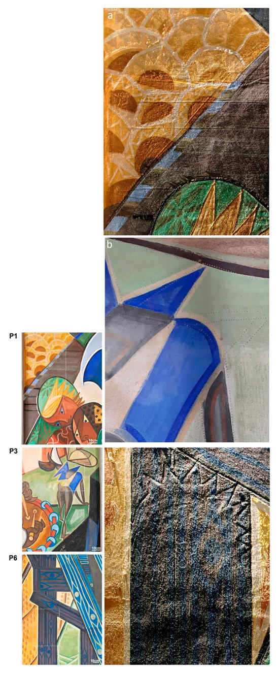
Figure 7.
Three examples in Vis-Rak (a,c) and Vis (b) of the variations found between the pounced drawings and the final painting on P1, P3, and P6 (photos by M. Ribeiro 2022).
The imprinted holes are seen in all the murals in the outlines of the figures and in some decorative and anatomic details. Even in the geometric motives in P6, this was the method most followed instead of the traditional beaten rope or incised lines with a pointed instrument. Not only did this method speed out the transfer process, but the marks left on the surface of the intonaco were visible enough to guide the artist in the next stages of the painting’s execution. Overall, Almada followed the drawings imprinted. Only a few variations and pentimenti are visible in all murals. Figure 7 shows some of the most obvious observed in P1, P3, and P6.
To date, no underdrawings made with charcoal were found by VIS or by the NIR images made on P1, P3, and P6. The exception is in a small area of P1, where the paint has peeled off and exposed a quick hatch made with a brown pigment. It is possible that this is not an isolated case and that Almada made others, but if he used a pigment that is less absorbent to IR radiation and similar to the ones used in the paint layers, it cannot be identified by the current analytical setup.
3.3. Paint Execution and Composition of the Paint Layers
In general, the same method for applying colours was followed throughout the set of paintings, which included coloured backgrounds, followed by successive layers of transparent to opaque paint for modelling, shading, and highlighting’s with final outlines in black and in other tones. The following text describes the main similarities and differences found in P1, P3, and P6.
The first noticeable feature is that Almada does not seem to have used the white intonaco as white paint ground or as a reflective layer. All the white paint grounds are achieved with another layer of calcium carbonate over the intonaco []. The other backgrounds of assorted colours, from light to dark, are generally very opaque, the brushstrokes being clearly visible on the thicker paint surfaces (Figure 8). The coloured backgrounds are also fairly homogeneous (Figure 8). The colour variations noted are given by (a) successive paint brushstrokes of the same pigment more or less diluted, (b) with a mixture of pigments, or (c) by increasing the white or black pigments in the composition (Table 2, Figure 8). The width of the different brushstrokes varies between 0.5 cm and 6 cm, revealing a wide use of brushes for different purposes, with the larger ones reserved mainly for the backgrounds and the thinner ones for the anatomic or decorative details (Figure 9).

Figure 8.
Detailed images in Vis of coloured backgrounds in P1, P3, and P6. In all, the different paint brushstrokes used to model the garments, flesh tones, and geometric motives can be observed (photos by M.Gil 2022).
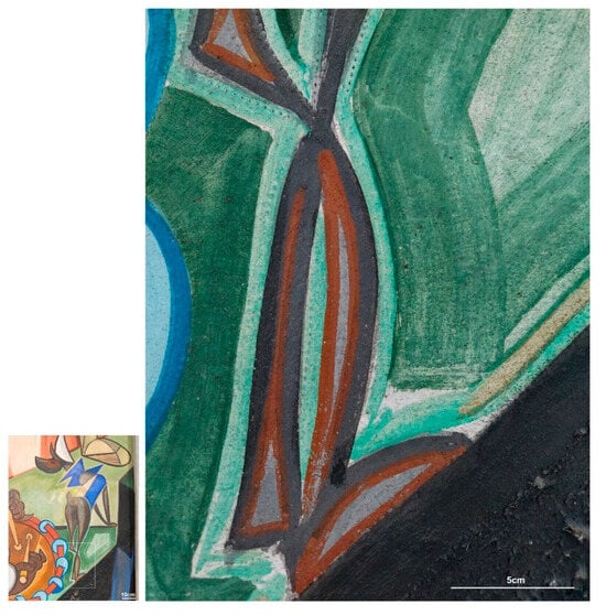
Figure 9.
Details of the different types of brushstrokes used on the green background and to shape the dog leg in P3. The strokes are made in such a way as to outline the shape so that it is clearly visible from a distance (photo by M.Gil 2022).
The paint layers, particularly the backgrounds, are generally very textured, and grains of aggregates can often be seen through the paint and even on the paint surface (Figure 10). In addition to the texture conferred by the granulometry of the top plaster and pigments used, it is possible that grains of calcium carbonates and sands were occasionally added to the paints, as is suggested on the flaking paint layers and on the cross-section in Figure 10.
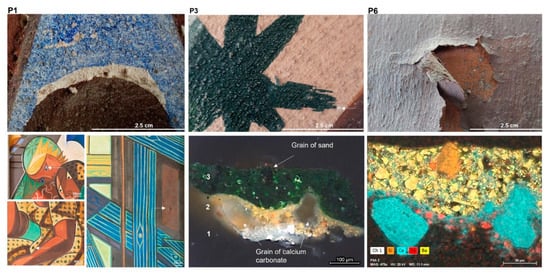
Figure 10.
On top, macro images of textured paint layers on murals P1, P3, and P6, with the sampling location of sample P3A_2 marked with a white arrow. On the bottom left, OM-Vis at 200× and SEM-EDS elemental map of the P3A_2 cross-section, showing the presence of aggregates grains of calcium (in blue) and silicium (in orange) in the yellow and green paint layers (2 and 3). Layer 1 is the intonaco. The SEM-EDS data of the paint layers are reported in Table 2.
Given the large size of the plaster sections of intonaco found in P1, P3, and P6, it is likely that Almada worked and reworked, as much as possible, the various parts of the composition during the day, from the backgrounds to the overlayed paint layers, whether he left or not enough time for the paint to dry between each layer. Figure 11 shows three examples of paint layers applied wet on wet and on a drier paint surface on P1, P3, and P6. The macro images reveal pigment contamination (and muddying), the cross-sections, the varying number of layers of paint placed, and their thickness.
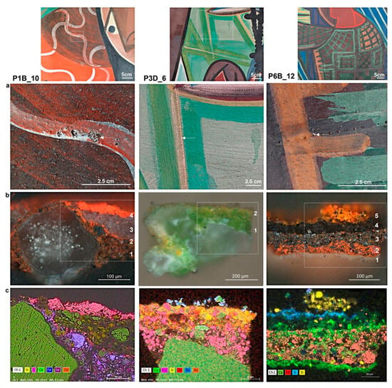
Figure 11.
From top to bottom, (a) details and macrophotography of the sampling places of samples P1B_10, P3D_6, and P6B_12; (b) OM-vis 200× of the paint layers cross-sections with the indication of the number of layers identified; (c) SEM-EDS elemental maps of the paint layers revealing the presence of Ca-, Fe-, Cd-Se-, and Cu-As-based pigments. The stratigraphic description of the paint layers and SEM-EDS data are reported in Table 2.
In all three murals, the amount of decoration details is quite significant and visually rich in terms of colours, patterns, and motifs. Each figure painted is different, as are all the decorative motifs (Figure 1). The paint structure does not follow a strict and rigid build-up from light to dark. Almada freely adapted according to the motif depicted and masterfully used primary and complementary colours to shade and give volume. To achieve the vivid colour palette present in all the murals, the artist did not confine himself to iron-based pigments, traditionally used in fresco mural paintings, as already reported in a previous study []. He has also resorted to the synthetic ultramarine blue and cadmium-based pigments, as well as the exotic but toxic copper (II)-acetoarsenite, commonly known as emerald green (Table 2). These pigments were used pure, mixed, and overlayed, as can be seen by OM-Vis in the paint layers of Figure 11.
Almada painted fast and with confidence and only seemed to leave for the next day the layers of paint and final black outlines that spanned over two (or more) patches of plaster. This procedure not only ensured the colour uniformity of the figuration/motifs carried out on different working days but also disguised the mortar joins, guaranteeing the visual continuity of the paint work (Figure 12). This work method is visible in P1, and particularly in P3, on the faces of the figures in the upper half of the composition (Figure 12a). In mural P6, there seem to have been exceptions in this regard that were left visible (Figure 12b). Moreover, changes were made to the composition during the painting work, and several drops of paint are also visible on the paint surface, sometimes poorly disguised (Figure 12c). Another difference found in P6 was the lack of transparent and semi-transparent paint layers compared to P1 and P3. The simultaneous use of fluid and more opaque brushstrokes creates optical differences and effects that visually enrich the composition. In P6, the paint layers are mostly opaque and rather thick, from the backgrounds to the final touches, giving the impression that Almada ran out of time and had to speed up the painting execution.
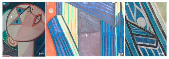
Figure 12.
Detailed images with the indication of the plaster join areas in P3 (a) and P6 (b) and details of the change in composition during the painting work in P6 (c). The figure’s face spans over two plaster sections and was painted with fluid brushstrokes over an opaque yellow background. The light pink layer and the anatomic details were made at the end to match the colour and disguise the plaster joins. On P6, this concern did not always occur, and colour differences are seen at the plaster joins (photos by M. Ribeiro and M. Gil 2022).
As far as painting techniques are concerned, Almada seems to have combined fresco and secco techniques; however, identifying the binders is not as straightforward due to past interventions, which used materials that may be similar to the original ones employed by the artist in 1949 (e.g., PVA and oil paints). Table 2 shows the summary results of OM, SEM-EDS, and µ-FTIR of the nine microsamples reported in Figure 5, Figure 10, Figure 11 and Figure 13. They were collected in the three murals and in different paint layers for stratigraphic analysis.


Table 2.
Summary results of OM (stratigraphy), SEM-EDS, and µ-FTIR of the nine microsamples of paint layers collected from murals P1, P3, and P6.
Table 2.
Summary results of OM (stratigraphy), SEM-EDS, and µ-FTIR of the nine microsamples of paint layers collected from murals P1, P3, and P6.
| Painting | Location | Colour | Sample Ref. | Stratigraphy (Number of Layers and Thickness) | SEM-EDS (at%) (Main Chromophore in Bold) | µ-FTIR |
|---|---|---|---|---|---|---|
| P3 | Background (edge of the painting) | Grey/black | P3A_13 | Figure 5: 3) black layer (≈43–224 µm) 2) brown layer (≈27–195 µm) 1) intonaco | Black (animal black): Ca (55.8), P (22.2), S (5.7), Si (3.9), Al (3.0), Na (4.0), Mg (2.1), Cl (1.4), Fe (1.2), K (0.8) Brown (Fe based pigment + C black): Ca (69.8), S (24.2), Si (2.4), Al (1.2), K (1.1), Fe (1.3); C (96.0), Ca (2.6), S (0.3), K (0.3), Cl (0.2), Na (0.9) | Black layer: gypsum, calcium carbonate, barite, polyvinyl alcohol (PVA) |
| P3 | Stars on the costume | Dark green | P3A_2 | Figure 10: 3) dark green layer (≈98–155 µm) 2) yellow layer (≈51–128 µm). 1) intonaco | Green (undetermined): Ca (56.2), S (18.3), Ba (16.3), Na (6.1), Fe (1.9), Al (0.4), Si (0.9) Yellow (Fe based pigment): Ca (51.6), Fe (17.5), Si (12.2), Al (11.5), K (2.5), Mg (0.3), S (1.5), Cl (1.6), Ba (1.4) | _ |
| P1 | Decorative motif on the costume | Red/white | P1B_10 | Figure 11: 4) red layer (≈13–87 µm) 3) white layer (≈53–132 µm) 2) red layer (≈3–4.72µm) 1) brownish red paint layer (≈2–100 µm) | Red (Cd-Se red + Fe based pigment): Cd (48.0), S (34.7), Se (13.8), Cl (1.0), Si (1.5), Fe (1.1) White (calcium carbonate): Ca (97.5), Si (1.0), S (0.5), Al (0.5), Cl (0.4); Brownish red (Fe based pigment +Cd yellow): Fe (54.8), Ca (14.1), Si (12.5), Al (7.00), Mg (3.4), K (2.6), S (2.5), Cl (1.6), Cd (1.5). | White layer: calcium sulphate, gypsumRed layer: gypsumBrownish layer: calcium sulphate, gypsum |
| P3 | Geometric motif on the background | Yellowish pink | P3D_6 | Figure 11: 2) yellow layer (no defined edges) 1) yellowish green layer (≈60–105 µm) | Yellow (Fe based pigment and Cu-As green): Ca (31.1), Al (26.8), Si (21.0), Fe (9.8), Cu (3.1), As (4.1), S (2.4), Cl (1.1), Ba (0.5) Green (Cu-As green): As (45.9), Cu (33.1), Ca (17.5), Si (1.4). S (1.0), Cl (1.1) | Yellow layer: kaolinite, gypsum, calcium carbonate, barite, polyvinyl alcohol (PVA)Green layer: kaolinite, gypsum, calcium carbonate |
| P6 | Costume | White | P1C_1 | Figure 13: 2) pinkish white layer (≈10 µm) 1) white layer (≈100–200 µm) | Black (animal black): Ca (78.0), P (17.5), S (2.1), Si (0.5), Mg (0.5), Na (1.5) | Polyvinyl alcohol (PVA) (glossy film at the surface), animal black, gypsum, oxalates, silicates |
| P1 | Black outline | Black | P1B_3 | Figure 13: black layer (≈100–180 µm) | Black (animal black): Ca (78.0), P (17.5), S (2.1), Si (0.5), Mg (0.5), Na (1.5) | Polyvinyl alcohol (PVA) (glossy film at the surface), animal black, gypsum, oxalates, silicates |
| P3 | Ball | bright green | P3C_3 | Figure 13: 2) green paint layer (≈30–100 µm) 1) yellowish white (≈20–60 µm) | Green (Cu-As): As (45.9), Cu (38.3), Ca (12.8), S (1.6), Cl (1.2), Fe (0.3) Yellowish white (Fe based pigment and calcium carbonate): Ca (23.6), Si (23.3), Al (18.8), Fe (13.8), Mg (10.0). K (4.0). As (2.9), Cu (1.2), S (2.5) | Green layer: gypsum, calcium carbonate; oxalates, polyvinyl alcohol (PVA) |
| P6 | Wood veins/ background | Yellowish-green/blue | P6B_9 | Figure 13: 2) yellowish green layer (≈30 µm) 1) blue layer (≈50–90 µm) | Yellow (Fe based pigment/Cr yellow/green?): Ca (57.3), Ti (27.0), S (6.5), Si (2.4), Fe (2.5), Al (1.8), K (1.4), Cr (1.2). The pigment is mixed with Ti white. Blue (ultramarine blue): Ba (48.7), Ca (15.5), S (11.1), Na (6.5), Si (6.3), Al (5.5), Cl (1.1), K (1.0), Cr (3.4), Fe (6.9), Cu (0.8). The blue pigment is mixed with Cr and Fe based pigments. | Blue layer: gypsum, calcium carbonate, barite, lipidic material |
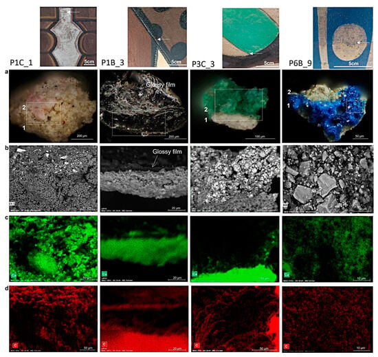
Figure 13.
From top to bottom, (a) Image details of the sampling places of samples P1C_1, P1B_3, P3C_3 and P6B_9 and OM-vis 400× of the paint layers, with the indication of the number of layers identified; (b) SEM backscattered images of the paint layers and constituents; (c,d) SEM-EDS elemental maps distribution of calcium (in green) and carbon (in red) confirming the presence of both elements in the paint structure. Stratigraphic description of the paint layers and SEM-EDS data are reported in Table 2.
The first feature noticed by OM is the number of layers of paint, up to four, with thickness reaching 155–180 µm in the green P3C_3 and black P1B_3 of Figure 13. In general, the structure of a fresco painting on its own tends to be simple because the colours have to be applied while the substrate is still fresh so that the pigments are bound by the carbonation reaction that occurs between the calcium hydroxide contained in the intonaco and atmospheric carbon dioxide. When more than two layers of paint are laid, and when thick layers of paint are applied last, an additional binder is usually required to ensure that the pigments are fixed to the surface.
Historically, several materials have been used for this purpose, from lime to organic substances of different kinds (e.g., egg, animal glues, casein, oil, etc.) [,]. However, in the official list of materials to be used in the field provided by Almada Negreiros in 1947, only lime and earth pigments are mentioned [].
The presence of lime in the nine samples analyzed was confirmed by µ-FTIR results that identified calcium carbonate in all the paint layers and by the elemental distribution maps of Ca in SEM-EDS analysis (Table 2). From the elemental distribution maps, it can also be seen that Ca was used as a binder when it is found in the composition of the matrix surrounding the pigment particles, but also as a white pigment and as an aggregate when identified in lumps (or grains) in the paint layer (Figure Figure 5, Figure 10, Figure 11 and Figure 13).
Given the large patches of mortar identified by Vis-Rak on P1, P3, and P6, it is likely that Almada only had time to paint at fresco the white and the coloured flat backgrounds, with the pigments previously mixed with lime in the thicker paint layers (example of P3A_2 in Figure 10). The overlapping layers of paint were most likely laid down at a later stage, with pigments mixed with lime milk (example of the pinkish and white layer of P1C_1 and of the black outline of P1B_3, Figure 13) or with an organic material (probably the green layer of P3C_3, Figure 13).
The use of organic binders in this set of paintings should be particularly considered for pigments that, according to the technical literature, must not be applied at fresco, such as emerald green, as it could turn to a yellowish-green copper arsenite when in contact with lime []. Emerald green was found in samples P3D_6 and P3C_3, but, to date, the only organic material identified by µ-FTIR in these paint layers was polyvinyl alcohol (PVA) (Table 2, Figure 14).
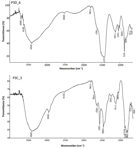
Figure 14.
On top, FTIR spectrum of the green layer of sample P3D6. The absorptions in the spectrum allowed the identification of kaolin group minerals (3693, 3619, 1037, 1009 cm−1), calcium sulphate dihydrate (3404, 1621, 1120, 670 cm−1), and calcium carbonate (2508, 1796, 1417, 873, 713 cm−1). The band at 825 cm−1 may be assigned to AsO or CrO elongations. On the bottom, FTIR spectrum of the green layer of sample P3C3. The absorptions in the spectrum allowed the identification of calcium sulphate dehydrate (3406, 1622, 1116 cm−1), calcium carbonate (2519, 1796, 1455, 873 and 714 cm−1), polyvinyl alcohol (2944, 1708, 1242 cm−1), silicates (1046 and 690 cm−1) and emerald green (1557, 1455, 822, 796 cm−1).
PVA was one of the adhesives applied by spraying in 1971 (and probably also in 1979) to fix flaking paint layers, so it was not a surprise when it was first identified on deteriorated paint layers in these paintings []. What was unexpected was the fact that it was found in the microsamples taken from paint layers in better conditions and with no signs of having been intervened on. Could this still be contamination from past treatments, or was polyvinyl also used by Almada Negreiros in 1949? This is an interesting question to explore, given the extensive presence of matt and glossy paint surfaces in this set of paintings.
By OM-Vis, PVA can clearly be seen as a translucid shiny layer on the surface of paint layers P3A_13 and P1B_3 in Figure 5 and Figure 13, respectively, and as a carbon-rich layer on SEM-EDS elemental map distribution in P1B_3, Figure 13. The identification of PVA by FTIR on the surface of the paint layers is straightforward since almost all the absorption bands displayed in the spectrum obtained are attributed to this compound. In layers with other materials, such as calcium carbonate, gypsum, or others, their bands overlap with most of the PVA bands in the infrared spectrum. Even so, their presence can be identified by the shape of the CH elongation band at around 2940–2944 cm−1, as in the case of the green layer of sample P3C_3 (Figure 14).
Apart from PVA, µ-FTIR analysis only revealed traces of unidentified organic material on the pink layer of P1C_1 and evidence of lipidic materials in the ultramarine blue paint layer of P6B_9. This blue layer in the OM-Vis at 400× shows it to be particularly thick and full-bodied with microbubbles formed by an energetic mixing action (Figure 13). Finally, the micro-FTIR analyses also revealed the presence of oxalates in the paint layers of P6B_12, P1B_3, and P3C_3, which may be related to the degradation of organic materials originally used as binders (Table 2). The subject of organic materials is quite intriguing in this group of paintings, so new research combining infrared spectroscopy and pyrolysis gas chromatography mass spectrometry (Py-GC-MS) is underway to shed light on this matter.
4. Conclusions
This article provides the first insight into how Almada created the murals in the maritime station of Rocha do Conde de Óbidos in Lisbon. It also highlights the innovations and technical difficulties he may have had while working on the paintings. Particularly interesting is the new type of pounced drawing found that has quickened the process of transferring the drawings in full scale to the walls, which is a clear example of his pragmatism. He worked mainly alone and on a tight schedule. To execute the six monumental mural paintings in just 29 days required extremely careful planning and fast execution on site. He could not afford to waste time. Proceeding by large patches of mortar with layers of paint applied while the mortar was still fresh, but also at a later stage of the carbonation process, would allow him to progress faster than with fresco paint alone.
The images and analytical results showed that the artist varied his way of painting depending on the motif depicted and the evolution of the work. The backgrounds are generally opaque and textured with clearly visible brushstrokes on the surface of the thicker paint layers, whereas the overlapping layers can vary from transparent to more opaque and full-bodied. Many such examples are found in P1 and P3, while in P6, presumably the last mural to be painted, Almada limits himself mostly to opaque brushstrokes. In this last mural, several drops of paint, changes in composition while painting, and joins of mortars poorly disguised can be seen, suggesting that Almada had been running out of time and in a hurry. The results also show Almada’s mastery of the use of colours in this set of paintings using natural and synthetic pigments. The most curious finding is the use of emerald green, a very bright but very toxic green pigment that, according to the technical literature, was not advised to be used in fresco paintings. In regard to the identification of organic compounds that may have been used by the artist, the pre-screening with micro-infrared spectroscopy alone proved to be very challenging. So far, in the nine microsamples analyzed, only polyvinyl alcohol was unequivocally identified, particularly at the paint surface as a surface glossy film. However, it is possible that other organic materials may have been used, but due to the superimposition of their absorption bands with those of carbonates or sulphates, their presence was not detected by μ-FTIR. Other analytical techniques like pyrolysis gas chromatography mass spectrometry (Py-GC-MS) will complement μ-FTIR results and will help clarify this matter in the future.
Author Contributions
Conceptualization, M.G.; methodology, M.G., M.C. and J.C.F.; validation, M.G., M.C. and J.C.F.; formal analysis, M.G., M.C. and J.C.F.; investigation, M.G., I.C., M.C. and J.C.F.; writing—M.G.; writing—review and editing I.C., M.C. and J.C.F.; project administration, M.G. All authors have read and agreed to the published version of the manuscript.
Funding
This research was funded by the Portuguese Foundation for Science and Technology (FCT) through project PTDC/ART-HIS/1370/2020, project UIDB/04449/2020, and contract programme Ref.ª CEECINST/00069/2021.
Data Availability Statement
Data not contained within the article but related to this study may be made available upon reasonable request from the corresponding author.
Acknowledgments
The present research was made in the framework of the project PTDC/ART-HIS/1370/2020: Unveiling the Mural Painting Art of Almada Negreiros (1938–1956). The authors want to acknowledge the professional photographer Manuel Ribeiro, the master students Keelie Rix and Youssef Ismael, and colleagues Sara Valadas and Margarida Padeira Nunes for their support on site and/or in the laboratory with OM, SEM-EDS, and FTIR. The authors also want to acknowledge. Claudia Pereira, Ana Paula Figueiredo, Head of the Archive, Inventory and Libraries Division/Sacavém Fort, as well as Alexandre Oliveira, Ana Carvalho Dias, Ana Paula Mendes, Cátia Martins, João Nuno Reis, Maria João Martins, Paula Noé, and Paula Tereno for their collaboration in researching and accessing the archival documentation.
Conflicts of Interest
The authors declare no conflicts of interest. The funders had no role in the design of the study; in the collection, analyses, or interpretation of data; in the writing of the manuscript; or in the decision to publish the results.
References
- Calouste Gulbenkian Museum. José de Almada Negreiros: Uma maneira de ser Moderno [Exhibition printed Catalogue]; Calouste Gulbenkian Museum: Lisbon, Portugal, 2017. [Google Scholar]
- Gil, M.; Costa, M.; Cvetkovic, M.; Bottaini, C.; Cardoso, A.M.; Manhita, A.; Barrocas Dias, C.; Candeias, A. Unveiling the Mural painting art of Almada Negreiros at the Maritime stations of Alcântara (Lisbon): Diagnosis research of the paint layers as a guide for its future conservation. Ge-Conservación 2021, 20, 105–117. [Google Scholar] [CrossRef]
- Gil, M.; Costa, M.; Cardoso, A.; Valadas, S.; Helvaci, Y.; Bhattacharya, S.; Moita, P.; Candeias, A. On the Two Working Palettes of Almada Negreiros at DN Building in Lisbon (1939–1940): First Analytical Approach and Insight on the Use of Cd Based Pigments. Heritage 2021, 4, 4578–4595. [Google Scholar] [CrossRef]
- Gil, M.; Helvaci, Y.; Mirão, J. Modern Mural Paintings. The Planisphere Painting of Almada Negreiros: Technical and Material Features of Plasters and Painting Technique. Int. J. Conserv. Sci. 2023, 14, 1265–1276. [Google Scholar] [CrossRef]
- Rix, K.S.; Valadas, S.; Cardoso, I.; Dias, L.; Gil, M. Preliminary Diagnostic Survey of Deteriorated Paint Layers at the Maritime stationof Rocha Do Conde De Óbidos, Lisbon: A Multianalytical Research. Int. J. Conserv. Sci. 2023, 14, 1249–1264. [Google Scholar] [CrossRef]
- Acevedo-Mejia, A.; Costa, M.; Vandenabeele, P.; Dias, L.; Frade, J.C.; Gil, M. An Insight into the Green Deteriorated Paint Layers of the Maritime station of Alcântara (Lisbon): An Archeometric Study. Int. J. Conserv. Sci. 2023, 14, 1185–1204. [Google Scholar]
- Lobo, P.R. Almada and the Maritime Stations: The portrait of Portugal that the dictatorship wanted to eras. Rev. História Arte 2014, Série W, 342–352. [Google Scholar]
- Almada Negreiros, M.J. Conversas com Sara Affonso, 3rd ed.; Publicação D. Quixote: Lisbon, Portugal, 1993. [Google Scholar]
- Fasani, A. Éléments de Peinture Murale pour une Technique Rationelle de la Peinture; Preface de le Corbusier; Blibliothèque de la technique moderne; Bordas: Paris, France, 1951. [Google Scholar]
- Borgioli, L. I Leganti Nell’arte Contemporânea; Nardini Editore: Firenze, Italy, 2020. [Google Scholar]
- Rainier, L.; Manning, L. Preserving América Tropical: From Original Technique to Conservation Treatment. In The Siqueiros Legacy: Challenges of Conserving the Artist’s Monumental Murals. In Proceedings of the Symposium Organized by the Gettry Conservation Institute, The Getty Center, Los Angeles, CA, USA, 16–17 October 2013. [Google Scholar]
- Mora, P.; Mora, L.; Philippot, P. Conservation of Wall Paintings; Butterworths: London, UK; ICCROM: Rome, Italy, 1984. [Google Scholar]
- Jimenez-Desmond, D.; Pozo António, J.S.; Arizzi, A. The fresco Wall paintings techniques in the Mediterranean area from Antiquity to the preset: A review. J. Cult. Herit. 2024, 66, 166–186. [Google Scholar] [CrossRef]
- Le Pittura Murali. Il Restauro e la Materia; Le antologie di OPD Restauro a cura di Cristina Danti; Centro Di. Alpi Lito: Firenze, Italy, 2007.
- Lazurlo, P.; Piqué, F.; Moretti, P. Gino Severini in Switzerland: A technical study of the wall paintings of Saint Nicolas de Myre in Semsales. Stud. Conserv. 2021, 68, 171–192. [Google Scholar]
- [Unpublished documents] PT PCIP/SIPA DGEMN: DSARH-005/125-4693/04: TXT.05422835 to TXT.05422838; TXT.05422902 a TXT.05422905.
- [Unpublished documents] PT PCIP/SIPA DGEMN: DSARH-005/125-4693/04: TXT.05422878 and TXT.05422879.
- [Unpublished documents] PT PCIP/SIPA DGEMN: DSARH-005/125-4693/04: TXT.05422883.
- Almada, Aquele, que não se Confunde com Nenhum Outro. Diário de Lisboa, nº 9808, Ano 29, Quarta, 22 de Março de 1950, Fundação Mário Soares/DRR—Documentos Ruella Ramos. Available online: http://hdl.handle.net/11002/fms_dc_22763 (accessed on 21 April 2024).
- Referência F.P.213 – Diário Popular – de 01-07-1945 a 30-09-1945, BOB. N.12, 943 fotogramas. Biblioteca Nacional de Portugal.
- Neves, A. Os murais do São Nobre da Assembleia Nacional no Contexto do Estado Novo. Núcleo de Investigação Práticas e Competências Mediáticas. Universidade Autónoma de Lisboa. 2021. Available online: https://nipcom.autonoma.pt/wp-content/uploads/2021/09/WP4_Anabela-Neves_Os-murais-do-Salao-Nobre-da-Assembleia-Nacional-no-contexto-do-Estado-Novo.pdf (accessed on 21 April 2024).
- Cardoso, S. Pintura Mural na cidade do Porto no Estado Novo. 120 f. Dissertação de Mestrado; Universidade do Porto: Porto, Portugal, 2013. [Google Scholar]
- França, J.A. A Arte em Portugal no Século XX (1911–1961), 4th ed.; Livros Horizonte: Lisbon, Portugal, 2009. [Google Scholar]
- Derrick, A.; Landry, M.R.; Stulik, J.M. Infrared Spectroscopy in Conservation Science; Getty Conservation Institute: Los Angeles, CA, USA, 1999. [Google Scholar]
- Gadsden, J.A. Infrared Spectra of Minerals and Related Inorganic Compounds; Butterworths: London, UK, 1975. [Google Scholar]
- Miller, F.A.; Wilkins, C.H. Infrared Spectra and Characteristic Frequencies of Inorganic Ions. Their Use in Qualitative Analysis. Anal. Chem. 1952, 24, 1253–1294. [Google Scholar] [CrossRef]
- Van de Marel, H.W.; Beutelspacher, H. Atlas of Infrared Spectroscopy of Clay Minerals and Their Admixtures; Elsevier: Amsterdam, The Netherlands, 1976. [Google Scholar]
- Kenney, J.F.; Willcockson, G.W. Structure–Property relationships of poly (vinyl alcohol). III. Relationships between stereo-regularity, crystallinity, and water resistance in poly (vinyl alcohol). J. Polym. Sci. Part A-1 1966, 4, 679–698. [Google Scholar] [CrossRef]
- Bhat, N.V.; Nate, M.M.; Kurup, M.B.; Bambole, V.A.; Sabharwal, S. Effect of γ-radiation on the structure and morphology of polyvinyl alcohol films. Nucl. Instrum. Methods Phys. Res. B 2005, 237, 585–592. [Google Scholar] [CrossRef]
- Thomas, P.S.; Guerbois, J.-P.; Russell, G.F.; Briscoe, B.J. FTIR study of the thermal degradation of poly(vinyl alcohol). J. Therm. Anal. Calorim. 2001, 64, 501–508. [Google Scholar] [CrossRef]
- Silverstein, R.M.; Bassler, G.C.; Morrill, T.C. Spectrometric Identification of Organic Compounds, 5th ed.; John Wiley & Sons, Inc.: Singapore, 1991. [Google Scholar]
- Madejová, J. FTIR techniques in clay mineral studies. Vib. Spectrosc. 2003, 31, 1–10. [Google Scholar] [CrossRef]
- Shurvell, H.F. Spectra-Struture correlations in the Mid- and far-infrared. In Handbook of Vibrational Spectroscopy; Chalmers, J.M., Griffiths, P.R., Eds.; John Wiley & Sons, Ltd.: Chichester, UK, 2002. [Google Scholar]
- Nakamoto, K. Infrared and Raman Spectra of Inorganic and Coordination Compounds. Part B: Applications in Coordination, Organometallic, and Bioinorganic Chemistry, 5th ed.; John Wiley & Sons, Inc.: New York, NY, USA, 1997. [Google Scholar]
- Fiedler, I.; Bayard, M.A. Emerald green and Scheele’s Green. In Artist Pigments: A Handbook of Their History and Characteristics; Elisabeth West Fitzhugh, Ed.; Nationally Gallery of Art. Oxfords University Press: Oxford, UK, 1997; Volume 3, pp. 219–271. [Google Scholar]
- Frost, R.L.; Bahfenne, S. Raman spectroscopic study of the arsenite minerals leiteite ZnAs2O4, reinerite Zn3(AsO3) and cafarsite Ca5(Ti,Fe,Mn)7(AsO3)12·4H2O. J. Raman Spectrosc. 2010, 41, 325–328. [Google Scholar] [CrossRef]
- Ito, K.; Bernstein, H.J. The vibrational spectra of the formate acetate, and oxalate ions. Can J. Chem. 1956, 34, 170–178. [Google Scholar] [CrossRef]
- Meiss, M. The Great Age of Fresco: Discoveries, Recoveries, and Survivals; George Brazillier in association with the Metropolitan Museum of Art: New York, NY, USA, 1970. [Google Scholar]
- Borsook, E. The Mural Painters of Toscany from Cimabue to Andrea del Sarto; Phaidon Press: Vienna, Austria, 1960. [Google Scholar]
- Casadio, F.; Giangualano, I.; Piqué, F. Organic materials in wall paintings: The historical and analytical literature. Stud. Conserv. 2004, 49, 63–80. [Google Scholar] [CrossRef]
- [Unpublished documents] PT PCIP/SIPA DGEMN: TXT.05422798 PT—Gare Marítima da Rocha do Conde de Óbidos Lisboa: Instituto Púbico (PCIP)/Forte de Sacavém.
Disclaimer/Publisher’s Note: The statements, opinions and data contained in all publications are solely those of the individual author(s) and contributor(s) and not of MDPI and/or the editor(s). MDPI and/or the editor(s) disclaim responsibility for any injury to people or property resulting from any ideas, methods, instructions or products referred to in the content. |
© 2024 by the authors. Licensee MDPI, Basel, Switzerland. This article is an open access article distributed under the terms and conditions of the Creative Commons Attribution (CC BY) license (https://creativecommons.org/licenses/by/4.0/).