Abstract
During the detailed design of magnets for the storage ring of Siam Photon Source II (SPS-II), the influence of magnetic crosstalk between adjacent magnets in the compact Double Triple Bend Achromat (DTBA) lattice was investigated. Using Opera-3D magnetostatic simulation, six magnet pairs were analyzed to investigate the changes in magnetic field distribution along the electron trajectory and integrated magnetic field within each magnet aperture. The study employed polynomial and Fourier analyses to calculate multipole field components. Results indicate that magnetic crosstalk affects the field distribution in the region between magnets, particularly for the defocusing quadrupole and dipole magnets (QD2-D01) and the focusing quadrupole and octupole magnets (QF42-OF1) pairs, which have the pole-to-pole distances of 153.37 mm and 116.45 mm, respectively. Although these separations exceed the estimated fringe field regions, deviations of up to 1% in the main field components were observed. Notably, even an unpowered neighboring magnet contributes to magnetic field distortion due to the modified magnetic flux distribution. Crosstalk effects on the higher-order multipole fields are mostly within the acceptable limit, except for the extra quadrupole field from QD2 found in the dipole D01 magnet. This study highlights the effects of magnetic interference in tightly packed lattice and underscores the need to include a complete multipole field data with crosstalk consideration in the SPS-II lattice model in order to ensure an accurate beam dynamics simulation and predict the operating current adjustments for machine commissioning.
1. Introduction
Siam Photon Source II (SPS-II), a highly brilliant 3 GeV synchrotron light source with the circumference of 327.5 m, is a compact machine with Double Triple Bend Achromat (DTBA) storage ring lattice design [1]. The DTBA lattice accommodates four 0.87 T dipoles and two 0.6 T combined function dipoles per cell with the optimized beam emittance of 0.97 nm·rad. SPS-II storage ring consists of 476 magnet elements, including 56 dipoles, 28 combined function dipoles, 224 quadrupoles with the field gradient ranging from 44 to 60 T/m, 84 sextupoles, 28 octupoles and 56 correctors [2]. In general, close intervals of the magnets in the lattice and the iron yoke saturation in high-field magnets [3] can cause prominent harmonic interference of magnetic field. This can distort the integrated field quality, alter the higher-order multipole terms and influence the beam performance and lifetime. Therefore, it is essential to evaluate the effects of magnetic crosstalk during machine design.
Effects of magnetic crosstalk have been studied at many facilities such as the European Synchrotron Radiation Facility (ESRF) [3,4], Taiwan Photon Source (TPS) [5,6], Advanced Photon Source Upgrade (APS-U) [7,8] and National Synchrotron Light Source II (NSLS-II) [9] to achieve reliable machine performance before machine commissioning. ESRF’s 6 GeV Hybrid Multi-Bend Achromat (HMBA) storage ring, which consists of 1200 magnets within the 844 m circumference, has the shortest magnets’ pole-to-pole distance of 47 mm. This pertains to the QD2-DL1 and DL1-QD3 magnet pairs with the quadrupole field gradient of 57 T/m for QD2, 53 T/m for QD3 and the dipole field of 0.17–0.67 T for the longitudinal gradient dipole DL1. The crosstalk analysis focuses on the changes in the integrated magnetic field of the main multipole and the distribution of the field gradient along the lattice. TPS’s 3 GeV storage ring of Double Bend Achromat (DBA) type, which has over 460 magnets installed within the circumference of 516.4 m, is less compact. The crosstalk analysis focuses on the sextupole–quadrupole pair, where the pole-to-pole distance is 150 mm. Attention is given to the changes in the error terms of the integrated magnetic field and installation of magnetic shielding. Besides crosstalk, fringe field effects of an adjacent unpowered magnet have also been explored. APS-U’s 6 GeV Multi-Bend Achromat (MBA) lattice consists of 1400 magnets in the storage ring of 1104 m circumference. The crosstalk analysis aims at the shortest distance of 50 mm between the quadrupole Q2 with the field gradient of 58 T/m and the longitudinal gradient dipole M1 with the dipole field of 0.13–0.64 T. The integrated field gradient of the quadrupole magnet shows 0.16% reduction, while the other multipole terms are within the allowed tolerance. By employing the Fourier analysis instead of the polynomial fitting of the integrated field, the error from the polynomial fitting range is curtailed.
In this work, crosstalk analysis is performed for SPS-II storage ring using Opera-3D magnetostatic simulation [10]. The magnetic field distribution along the lattice longitudinal path as well as the impact of crosstalk on the main field component and multipole errors from both the polynomial and Fourier analysis of the integrated field are investigated. The simulation focuses on six magnet pairs where the pole-to-pole distance ranges from 116.45 mm to 153.37 mm.
2. SPS-II Storage Ring
Layout of the DTBA lattice (half-cell) of SPS-II storage ring is illustrated in Figure 1. D01 and D02 are dipole magnets. DQ1 is combined function dipole magnet. QF and QD are focusing and defocusing quadrupole magnets. SF and SD are focusing and defocusing sextupole magnets. Lastly, OF1 is octupole magnet. The magnets’ pole-to-pole distance, coil-to-coil distance and aperture are listed in Table 1.
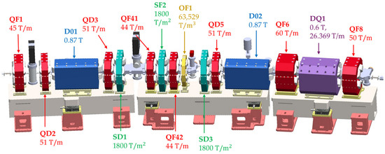
Figure 1.
Half-cell of SPS-II’s DTBA lattice.

Table 1.
Longitudinal distance between the magnets and magnet aperture of SPS-II storage ring.
It is apparent that the dense region is in the center of the half-cell, with the shortest pole-to-pole and coil-to-coil distances of 116.45 mm and 21.00 mm, respectively. These are between the quadrupole QF42 and octupole OF1 magnets, and between the quadrupole and sextupole magnets, respectively. Table 1 shows that the pole-to-pole distance is greater than the sum of adjacent magnet apertures for all magnet pairs. Therefore, the fringe field and crosstalk effects are expected to be small. The crosstalk simulation is performed on QD2-D01, SF2-QF42, QF42-OF1, SD3-QD5, QF6-DQ1 and DQ1-QF8 magnet pairs. Adjacent magnets with the pole-to-pole distance above 300 mm are neglected as the crosstalk becomes insignificant. Other magnet pairs with the same pole-to-pole distance, magnet aperture and magnetic field are also disregarded.
3. Crosstalk Simulation and Analysis
In the magnetic field simulation, two adjacent magnets are modeled in Opera-3D with the actual distance and angle between them. The magnet yoke is made of AISI 1006 low-carbon steel with carbon content below 0.08%. B-H curve of material is used in a non-linear magnetostatic solver with an isotropic assumption. Generally, during the magnet design process, model symmetry is used along the XY, XZ, and YZ planes with tangential or normal magnetic field at the boundary. In crosstalk simulation, some of these symmetry settings are omitted when two magnets are in the model. Element size in the air region at the magnet center is 1 mm for dipole magnet and 0.5 mm for other multipole magnets. The element size in the less important area is made larger. Maximum angle between elements is 30 degrees, which is the default setting. Convergence tolerance in the simulation is 0.0001. For each pair of magnets (Magnet A and Magnet B), five cases of magnet model and powering are studied, as summarized in Table 2.
Table 2.
Crosstalk simulation for each pair of Magnet A and Magnet B.
In Simulation 1, there is only Magnet A in the model, and it is powered at the designed operating current (). In Simulation 2, on the other hand, there is only Magnet B in the model which is powered at its operating current (). In Simulation 3 and Simulation 4, both Magnet A and Magnet B are in the model but only one magnet is powered. Lastly, in Simulation 5, both magnets are in the model, and both powered at their operating current. In magnetic field calculation, Magnet A and Magnet B are separated at the intersection point , defined at the position where the superposed magnetic field from Simulation 1 and Simulation 2 drops to a minimum or has a value close to zero. When analyzing the magnetic field integral of each magnet, the integration limit is either from to or from to .
For the QD2-D01 pair, the dipole D01 magnet is centered at () = (); the quadrupole QD2 magnet is centered at () and makes an angle of 2.485° from the magnet center line, as illustrated in Figure 2a. The magnet yoke is shown in green, and the magnet coils are in red. For the SF2-QF42 pair, the sextupole SF2 magnet is centered at (); the quadrupole QF42 magnet is centered at (). For the QF42-OF1 pair, the quadrupole QF42 magnet is centered at (); the octupole OF1 magnet is centered at (). For the SD3-QD5 pair, as shown in Figure 2b, the sextupole SD3 magnet is centered at (); the quadrupole QD5 magnet is centered at (). For QF6-DQ1 pair, the combined function dipole DQ1 magnet is centered at (); the quadrupole QF6 magnet is centered at () and makes an angle of 1.460° from the magnet center line. For the DQ1-QF8 pair, the DQ1 magnet is centered at (); the quadrupole QF8 magnet is centered at () and makes an angle of 1.460°.
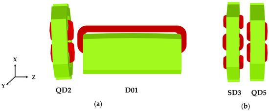
Figure 2.
Opera-3D model of QD2-D01 pair (a) and SD3-QD5 pair (b).
The two-dimensional magnetic field of a multipole magnet is described by:
where and = 1, 2, 3, … for dipole, quadrupole, sextupole, … components of the magnetic field. and are normal and skew multipole components in Tesla, respectively. Harmonic analysis of magnetic field (calculation of and ) is performed within a circle of radius , defined as normalization or reference radius. This can be either calculated from magnetic field at the magnet center as written in Equation (1) or calculated as integrated multipole components and in Tesla meter from integrated magnetic field along the electron trajectory ( and ) as written in Equation (2). L is the effective length of the magnet.
The integrated vertical magnetic field at the mid-plane () can be derived from Equation (2) as:
which is in the form of polynomial expansion. The integrated normal multipole component or can also be obtained from the polynomial least square fit to the integrated magnetic field Iy(x) data. In this work, both polynomial and Fourier analyses are employed to calculate the integrated multipole components of magnetic field. Polynomial analysis is required for the dipole D01 and combined function dipole DQ1 magnets to compare with the measurement because the magnetic field mapping of these magnets will be performed using a Hall sensor scanned along the XZ plane. Magnetic field measurement of other multipole magnets will be performed using a circular scan in the stretched wire technique; therefore, the Fourier analysis is more appropriate. Comparison between the two analysis methods is made and described in Section 4.
4. Crosstalk Effects
4.1. Crosstalk Effects on Magnetic Field Distribution
To investigate the crosstalk effects on magnetic field distribution, the calculated vertical magnetic field along the electron trajectory for each magnet pair is plotted for Simulations 1, 2, 5 and the superposition of the results from Simulations 1 and 2. By observation, if the influence of crosstalk is insignificant, the plot of Simulation 5 and the superposition of Simulations 1 and 2 will overlap. On the other hand, strong crosstalk effects cause their separation, as seen in Figure 3.
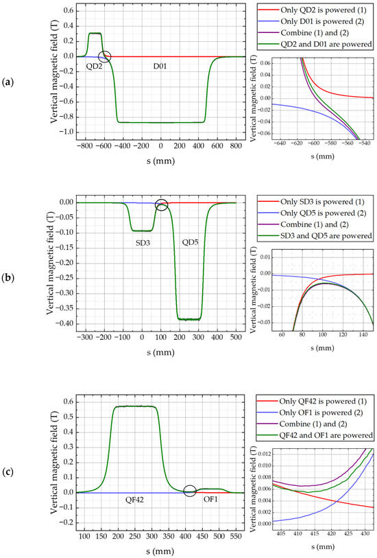
Figure 3.
Vertical magnet field along electron trajectory: (a) for QD2-D01 pair at x = −10 mm; (b) for SD3-QD5 pair at x = 10 mm; and (c) for QF42-OF1 pair at x = 13 mm.
Figure 3 illustrates the vertical magnetic field profiles along the electron trajectory for three magnet pairs which can represent a weak and strong crosstalk effects on magnetic field distribution: QD2–D01, SD3–QD5, and QF42–OF1. The magnetic field is extracted at the transverse location corresponding to the smaller good field region (GFR) between the two magnets in each pair. In the plots, the red and blue lines are the vertical magnetic fields produced by Magnet A and Magnet B, respectively, with a single magnet in the model. The purple line shows the linear superposition of these individual fields, representing the expected magnetic field distribution in the absence of magnetic interaction between two magnets. In contrast, the green line depicts the actual field distribution when both magnets are simultaneously powered, thus capturing the effect of magnetic crosstalk.
As shown in the enlarged view of Figure 3a, for the QD2–D01 pair, a noticeable deviation between the green and purple lines is observed, with the green line lying above the purple line. This indicates an enhancement of the vertical magnetic field in the region between the magnets due to magnetic coupling. The point of magnetic field separation between QD2 and D01 is located at s = –600 mm. A similar behavior is evident in Figure 3c for the QF42–OF1 pair, where the green and purple lines diverge, reflecting a significant crosstalk effect. In contrast, Figure 3b demonstrates near-complete overlap between the green and purple lines for the SD3–QD5 pair, suggesting negligible magnetic interference. A quantitative analysis of the resulting deviations in the main field components is presented in Section 4.2.
4.2. Crosstalk Effects on the Main Multipole Field
The influence of unpowered adjacent iron yoke and the effect of the excited neighboring magnet are summarized in Table 3 and Table 4, respectively. As shown in Table 3, Fourier analysis reveals that the integrated dipole field component of D01 magnet is significantly affected by the presence of the unpowered neighboring magnet QD2, resulting in a 0.1% increase in the dipole field integral. Polynomial analysis also gives a similar increase in the dipole field of 0.09%. According to the polynomial analysis, notable deviations in the main field components are also observed for the QF42-OF1 pair as well as for the SD3-QD5 pair. However, the deviations are much smaller in the Fourier analysis. Reliability of the polynomial fit for higher-order multipoles (n ≥ 2) is generally limited due to the strong dependence of term and the sensitivity to the fitting range used in the linear regression. Consequently, the results derived from the Fourier analysis are considered more robust. In addition, Fourier method analyses the magnetic field on the XY plane within the defined reference radius, while polynomial method only analyses the magnetic field along the X axis (at y = 0). Therefore, the results from Fourier analysis are used in this work as the primary reference for assessing magnetic interference effects. In the dipole D01 magnet, results from the two methods agree because the magnetic field is more uniform along the XY plane and the polynomial analysis can give an accurate result for n = 1.
Table 3.
Impact on the main multipole field of each magnet due to the presence of an unpowered neighboring magnet.
Table 4.
Impact on the main multipole field of each magnet due to the presence of a neighboring magnet powered at their respective operating current.
Excitation of the neighboring magnet during machine operation introduces measurable magnetic crosstalk, as evidenced by the data presented in Table 4. Fourier analysis identifies SD3-QD5 pair as exhibiting the most pronounced interaction, where the quadrupole field integral of QD5 is increased by 0.21%. The next most significant crosstalk effect is observed for the QD2-D01 pair, which experiences up to 0.1% change in the main field component of the dipole D01 magnet. Similarly to the results presented in Table 3, polynomial analysis also reveals significant main field deviations in the SF2-QF42 and QF42-OF1 pairs which are larger than the results from Fourier analysis.
The simulation results presented in Table 3 and Table 4 illustrate that, in many cases, variations in the magnetic field arise from the presence of a neighboring magnet, even when it is unpowered. This effect is primarily attributed to the influence of surrounding magnetic materials, such as iron poles and yokes, which alter the magnetic flux distribution in the region between the two magnets. If an additional magnet excitation is applied within the linear regime (below the threshold of magnetic saturation in iron), its contribution to further field distortion remains minimal.
4.3. Crosstalk Effects on the Multipole Field Errors
Due to the accuracy limitation of polynomial fitting as mentioned above, crosstalk effects on the multipole errors, particularly the higher-order multipole terms, are investigated using Fourier analysis only. Fourier transformation of the magnetic field is calculated at the magnet’s reference radius, extending to the 15th order (n = 15). For clarity, only the results up to the 9th order (n = 9) are presented in Figure 4.
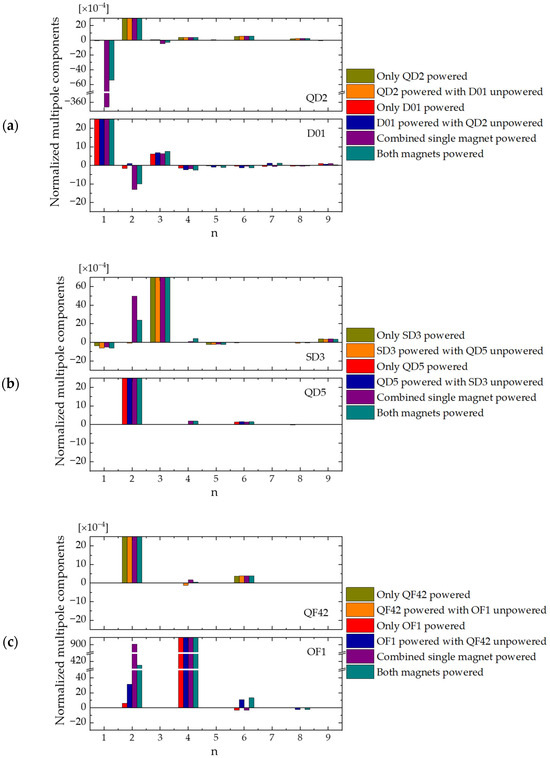
Figure 4.
Normalized integrated multipole components: (a) for QD2-D01 pair; (b) for SD3-QD5 pair; and (c) for QF42-OF1 pair.
Integrated multipole components of the QD2-D01, SD3-QD5, and QF42-OF1 pairs are presented in Figure 4a to Figure 4c. The results are normalized to the main multipole field of each magnet. Fringe field from adjacent magnet is clearly observed in the multipole field analysis, such as the dipole term in QD2, the quadrupole term in D01, SD3, and OF1, etc. The actual crosstalk induced multipole errors are the difference between the results from ‘Both magnets powered’ and ‘Combined single magnet powered’. For the QD2-D01 pair, the crosstalk reduces the normalized dipole component in QD2 from −365 units to −54 units and the normalized sextupole component from −4.7 units to −3.0 units (1 unit = 1 × 10⁻⁴). It also decreases the normalized quadrupole component in D01 from −13 units to −10 units. Changes in the other multipole terms are negligible. For the SD3-QD5 pair, only the normalized quadrupole component in SD3 is significantly changed, where it is reduced from 50 units to 24 units. Crosstalk effects on the other multipole terms are very small. Lastly, for the QF42-OF1 pair, the quadrupole QF42 magnet shows an increase in the normalized octupole component that is still within the tolerance of 5 × 10⁻⁴ for quadrupole magnet. On the other hand, the octupole OF1 magnet shows a large increase in the normalized quadrupole component in the region of OF1 due to fringe field of QF42. However, the crosstalk reduces this quadrupole component from 901 units to 415 units when both magnets are powered. Effects of fringe field and crosstalk on the multipole fields of the SF2-QF42, QF6-DQ1, and DQ1-QF8 pairs (not presented here) show similar behaviors.
It is apparent that fringe field from the neighboring magnet shows up in the multipole analysis when the magnets are modeled separately. When the two magnets are in the same model and both are powered, which is the real situation of machine operation, this multipole term tends to drop by a factor of 2–7. This factor is expected to be influenced by the field strength, bore radius, magnet separation, magnetic saturation, and direction of the magnetic field, which can alter the magnetic flux distribution. A comprehensive investigation of this phenomenon is beyond the scope of the present study.
Crosstalk-induced deviations in the main field components, particularly in quadrupole and sextupole magnets which are operated with separated power supplies, can be efficiently compensated by adjusting the excitation current of the affected magnets. For dipole and combined function dipole magnets, which are electrically connected in series, magnetic field correction of individual magnets can be implemented using trim coils. Tolerance of the main field errors is 0.1% for all magnets in the lattice design. Therefore, a field correction in octupole magnet based on Fourier analysis is not strictly required. Tolerance of the multipole errors varies from magnet to magnet. Allowable multipole errors normalized to the main field are 2 × 10⁻⁴ for dipole, 5 × 10⁻³ for combined function dipole, 5 × 10⁻⁴ for quadrupole, 1 × 10⁻³ for sextupole, and 5 × 10⁻³ for octupole magnets. For each magnet type, the tolerance is the same for every multipole term. In most cases, except for quadrupole field in dipole D01 magnet, the higher-order multipole errors with crosstalk effects are within the tolerance. In contrast, the lower-order multipole errors arising from crosstalk between magnets are much higher. The results will need to be integrated into the lattice model to investigate the effects on beam dynamics and finely tune the operating current of each magnet in the storage ring. This compensation technique is crucial for ensuring the required magnetic field quality and maintaining the beam stability during storage ring operation.
5. Conclusions
This study demonstrates that magnetic crosstalk between adjacent magnets in the SPS-II DTBA lattice, including effects from unpowered magnets, causes measurable but small (less than 1%) changes in the main multipole field component. While the higher-order multipole errors are mostly within the acceptable limit, the multipole terms that arise from the main field of neighboring magnets are relatively large. These variations appear primarily from the presence of magnetic material such as iron poles and yokes of nearby magnets. Crosstalk and fringe field effects can be mitigated by adjusting the excitation current for individual quadrupole and sextupole magnets, and by using trim coils for dipole and combined function dipole magnets. Incorporating these corrections and accounting for magnetic crosstalk in the lattice model will be essential to ensure the desired magnetic field quality and stable machine operation for SPS-II.
Author Contributions
Conceptualization, P.S. and S.P.; methodology, P.S.; formal analysis, W.T.; investigation, P.S.; writing—original draft preparation, W.T.; writing—review and editing, P.S.; visualization, W.T., T.L. and P.S. All authors have read and agreed to the published version of the manuscript.
Funding
This research received no external funding.
Data Availability Statement
Data sharing is not applicable to this article.
Conflicts of Interest
The authors declare no conflicts of interest.
References
- Klysubun, P.; Pulampong, T.; Sudmuang, P. Design and optimisation of SPS-II storage ring. In Proceedings of the 8th International Particle Accelerator Conference (IPAC2017), Copenhagen, Denmark, 14–19 May 2017; pp. 2773–2775. [Google Scholar]
- Sunwong, P.; Prawanta, S.; Phimsen, T.; Sudmuang, P.; Klysubun, P. Magnet Design for Siam Photon Source II. In Proceedings of the 10th International Particle Accelerator Conference (IPAC2019), Melbourne, Australia, 19–24 May 2019; pp. 4361–4363. [Google Scholar]
- Le Bec, G.; Chavanne, J.; Liuzzo, S.; White, S. Cross talks between storage ring magnets at the Extremely Brilliant Source at the European Radiation Facility. Phys. Rev. Acc. Beams 2021, 24, 072401. [Google Scholar] [CrossRef]
- Liuzzo, S.M.; Carmignani, N.; Chavanne, J.; Farvacque, L.; Le Bec, G. Updates on Lattice Modeling and Tuning for the ESRF-EBS Lattice. In Proceedings of the 7th International Particle Accelerator Conference (IPAC2016), Busan, Republic of Korea, 8–13 May 2016; pp. 2818–2821. [Google Scholar]
- Kuo, C.C.; Chang, H.P.; Chao, H.C.; Chou, P.J.; Luo, G.H.; Tsai, H.J. Progress Report of TPS Lattice Design. In Proceedings of the 2009 Particle Accelerator Conference (PAC09), Vancouver, BC, Canada, 4–8 May 2009; pp. 2273–2275. [Google Scholar]
- Kuo, C.Y.; Hwang, C.S.; Chang, C.H. Magnet Field Crosstalk Effect of TPS Storage Ring Magnets. In Proceedings of the 1st International Particle Accelerator Conference (IPAC2010), Kyoto, Japan, 23–28 May 2010; pp. 325–327. [Google Scholar]
- Abliz, M.; Jaski, M.; Jain, A.; Borland, M.; Decker, G.; Kerby, J. Magnetic cross-talk simulation between Q2 and L-bend magnets of APS-U. Nucl. Instrum. Methods Phys. Res. A 2019, 913, 48–53. [Google Scholar] [CrossRef]
- Abliz, M.; Borland, M.; Kerby, J. Magnetic Crosstalk Between the Q1, FS1, and Q2 Magnets in the Advanced Photon Source Upgrade Lattice; ANL/APS/LS-368; Argonne National Laboratory: Lemont, IL, USA, 2023. [Google Scholar]
- Gupta, R.; Jain, A. Special Magnet Designs and Requirements for Next Generation Light Sources. In Proceedings of the 2009 Particle Accelerator Conference (PAC09), Vancouver, BC, Canada, 4–8 May 2009; pp. 614–618. [Google Scholar]
- Opera-3D 18R2 Reference Manual; Dassault Systèmes UK Ltd.: Kidlington, UK, 2018; pp. 1–918.
Disclaimer/Publisher’s Note: The statements, opinions and data contained in all publications are solely those of the individual author(s) and contributor(s) and not of MDPI and/or the editor(s). MDPI and/or the editor(s) disclaim responsibility for any injury to people or property resulting from any ideas, methods, instructions or products referred to in the content. |
© 2025 by the authors. Licensee MDPI, Basel, Switzerland. This article is an open access article distributed under the terms and conditions of the Creative Commons Attribution (CC BY) license (https://creativecommons.org/licenses/by/4.0/).