Article

Design and Prototype Development of a Combined-Function Quadrupole-Sextupole Magnet for the SPS-II Booster Synchrotron

Synchrotron Light Research Institute, Muang District, Nakhon Ratchasima 30000, Thailand
*
Author to whom correspondence should be addressed.
Particles 2025, 8(3), 77; https://doi.org/10.3390/particles8030077
Submission received: 30 June 2025 / Revised: 25 August 2025 / Accepted: 26 August 2025 / Published: 28 August 2025
(This article belongs to the Special Issue Generation and Application of High-Power Radiation Sources 2025)

Abstract

The development of a prototype booster magnet for the Siam Photon Source II (SPS-II) was launched in 2023 as a milestone in advancing accelerator technology through domestic manufacturing capabilities in Thailand. In the SPS-II booster lattice, the magnet integrates focusing quadrupole and sextupole functions into a combined-function quadrupole-sextupole magnet, enabling a more compact lattice and reducing the total number of magnets required. To meet the required magnet specifications, the design was carefully optimized using Opera-3D software (version 2021) to achieve a quadrupole gradient of 19.395 T/m and a sextupole gradient of 22.327 T/m2 over an effective magnetic length of 0.25 m, while maintaining a magnetic field homogeneity better than 1 × 10⁻³. A key manufacturing challenge involved fabricating laminated magnet cores and establishing precise production processes. Magnetic field measurements performed on the prototype using the Hall-probe technique validated the magnet’s quality and accuracy. This paper presents the overall development process, including the magnet design, details of the magnetic field simulation methodology, prototype fabrication, and initial magnetic field measurements.

1. Introduction

Siam Photon Source II (SPS-II) is a next-generation synchrotron light source planned for development in Thailand, aiming to become a leading scientific infrastructure for Southeast Asia. Designed as a fourth-generation facility, SPS-II will offer synchrotron light with intensities exceeding those of the current Siam Photon Source (SPS) by more than a factor of one million. This remarkable increase in brightness and photon energy will enable cutting-edge experiments and open up new research possibilities [1,2]. The SPS-II project adopts an injector system that combines an injector linac with a booster synchrotron, a widely used configuration in synchrotron facilities worldwide, such as Sirius, TPS, NSLS-II, and SLS2.0 [3,4,5,6]. Compared to a full-energy linac, this combination offers lower construction and operational costs, owing to the maturity of booster synchrotron technology. Although a full-energy linac requires fewer magnets, it demands more RF accelerating structures and higher power consumption. For SPS-II, the linac-booster approach is particularly well-suited, as it leverages the extensive experience of the Synchrotron Light Research Institute (SLRI) with the existing SPS machine and aligns with our commitment to developing accelerator components domestically.
At present, various types of magnets are being developed domestically, including quadrupole magnets that are critical components of the booster synchrotron. The initial prototype focused on a combined-function quadrupole-sextupole magnet (combined quadrupole), which is integrated into the booster lattice to minimize the number of standalone sextupole magnets and reduce the required sextupole field strength.

1.1. Original Design of SPS-II Booster

Since the development of this prototype, various aspects of the booster design have been revised to improve overall machine performance during operation. The original booster lattice design [7], based on an RF frequency of 119 MHz and incorporating this combined-quadrupole prototype, is described in the following section.
For the SPS-II booster synchrotron, a FODO lattice employing combined-function magnets is a suitable configuration, as it enables the achievement of low beam emittance. Combined-function magnets offer key advantages, including compactness and cost-effectiveness. The proposed SPS-II booster lattice consists of 40 modified FODO cells equipped with combined-function magnets, designed to deliver both the low emittance and high injection efficiency necessary for top-up operation. The total circumference of the booster is 304.829 m. The lattice features eightfold symmetry, with each symmetric section comprising five FODO cells. The length of one symmetric section is 38.1036 m. Two types of combined-function magnets are utilized: the combined dipole magnet (BD) and the combined-function quadrupole-sextupole magnets (referred to as combined quadrupoles, QF), which integrate focusing quadrupole and sextupole field components. Within each symmetric section, combined quadrupoles are positioned between two BD magnets. Additional defocusing quadrupole magnets (QD) are placed downstream of the BD in the second and fourth symmetric sections. Extra sextupoles (SF, SD) are installed downstream of the first and fifth BD magnets in each symmetric section.
Figure 1 illustrates the schematic layout of one symmetric section, showing the placement of key magnetic elements: dipoles (blue), quadrupoles (red), sextupoles (green), correctors (pink), and beam position monitors (BPMs, orange). A summary of the booster magnet design parameters is provided in Table 1. With this configuration, a low beam emittance of 5.87 nm·rad can be achieved.
This paper is organized into six main sections: Introduction, Requirements and Design Parameters, Magnet Design and Simulation, Magnet Prototype, Results and Discussion, and Conclusions. Section 2 outlines the specifications for the magnet. Section 3 provides a comprehensive overview of the design methodology and magnetic field simulations. Section 4 describes the fabrication process and the experimental setup for magnetic field measurements. Section 5 offers a detailed comparison between simulation and measurement results, highlighting the key findings and insights gained from prototype development. Finally, Section 6 summarizes the main outcomes of the study.

1.2. Combined-Function Quadrupole-Sextupole Magnet (Combined Quadrupole)

A quadrupole magnet is a crucial magnetic element used in particle accelerators to focus charged particle beams in the transverse plane. It comprises four magnetic poles arranged with alternating polarity, including two north poles and two south poles. The pole faces are oriented at 45 degrees with respect to the horizontal and vertical axes. This configuration generates a magnetic field whose strength increases linearly with the distance from the magnet’s center, providing focusing action in one transverse direction while simultaneously defocusing in the perpendicular direction. The ideal magnetic field distribution is achieved by shaping the pole faces with a hyperbolic profile described by the equation xy = ±R2/2, where R is the bore radius, which corresponds to the aperture of the magnet. This design is typical of a conventional pure-quadrupole magnet [8].
The combined-quadrupole magnet offers distinct advantages, such as cost-effectiveness. However, the evident disadvantage is that the focusing and second-order correction cannot be separately controlled. To implement a combined-quadrupole field, the pole profiles in the upper two quadrants are rotated clockwise on the right-hand side to introduce the desired sextupole field component.
To integrate the quadrupole and sextupole field components within a single magnet, the transformation of the pole profile is carried out by rotating from the original xy-Cartesian coordinate system to a new xy′-Cartesian coordinate system [9]. This method can be applied to the design of the pole geometry for a combined-function quadrupole magnet. The equations for the transformed coordinates are given by
x = x c o s θ + y s i n θ ,
y = x s i n θ + y c o s θ ,
where θ is the angle of rotation.
To achieve the desired sextupole field strength in a combined-quadrupole magnet, the pole profiles in the top two quadrants are rotated clockwise. This rotation generates the required sextupole component but also introduces an unwanted dipole field. To compensate for this, the bore radius between the first and second poles is carefully optimized to suppress the dipole component. Furthermore, to enhance the region with favorable field quality, shims are applied at the right and left poles. Additionally, chamfers are introduced at these poles to reduce the influence of higher-order harmonic field components.

2. Requirements and Design Parameters

This report aims to design a combined-quadrupole magnet with field gradients of 19.395 T/m and 22.327 T/m2 for the quadrupole and sextupole terms, respectively. This quadrupole magnet offers an effective length of 0.25 m. The required Good Field Region (GFR) is ±15 mm, where the multipole errors are less than 1 × 10⁻³. This ensures coverage of the calculated horizontal beam stay-clear region of ±15 mm at the center of the straight section in the booster lattice.
To meet the booster lattice design in the beam dynamics simulation, the required magnetic field strength is 1.9381 m−2 for the quadrupole term and 2.2311 m−3 for the sextupole term, with the negative sign representing a horizontal defocusing effect. At an excitation level of 4890.38 A-turns and a bore radius of 23 mm, the corresponding magnetic field gradients for a beam energy of 3 GeV are calculated to be 19.395 T/m for the quadrupole component (G) and 22.327 T/m2 for the sextupole component (G′) with the following equations [10]:
For the quadrupole term (k),
k = B B 0 ρ , k m 2 = 0.2998 G [ T / m ] β E [ G e V ] ,
For the sextupole term (m),
m = B B 0 ρ , m m 3 = 0.2998 G [ T / m 2 ] β E [ G e V ] ,
where the parameter β = v/c ≈ 1 represents the relative electron velocity, and the electron energy E is 3.0 GeV.

3. Magnet Design and Magnetic Field Simulation

The modeling and magnetic field calculations of the quadrupole magnets are primarily performed using Opera-3D (version 2021) [11]. Opera is a software suite used for electromagnetic simulations across a range of engineering applications. Developed by Cobham Technical Services (formerly Vector Fields), Opera-3D is its key module for three-dimensional simulations using the finite element method (FEM). There are four primary steps in conducting a magnetic field simulation using Opera-3D, encompassing magnet geometry, coil, air condition, and analysis.
For mechanical analysis, when manufacturing the prototype magnet, it is crucial to incorporate engineering design considerations to ensure structural integrity and performance. A comprehensive mechanical analysis of the magnet structure was performed using ANSYS (version 2022) [12] for detailed mechanical analysis simulation. This analysis included evaluating the static deformation of the magnet structure under operational loads, such as the magnetic forces and the weight of the coils, as well as conducting a modal analysis to assess the vibrational characteristics of the structure.

3.1. Magnet Geometry

The magnets are designed to have dimensions that do not exceed 400 mm × 400 mm. This size limitation ensures adequate space between the booster synchrotron and the storage ring, both situated within the same tunnel. A model of the combined-quadrupole magnet used for magnetic field calculations is shown in Figure 2 (left). The magnet yoke is shown in green, and the coils are highlighted in red.
For fabrication purposes, the pole is shaped at a 65° angle with respect to the horizontal axis, while the pole tip is precisely maintained at 45° to ensure the desired field profile. The pole profile of this combined-quadrupole magnet is illustrated in Figure 2 (right). Initially, the pole shape is calculated using xy = ±R2/2, where R is the bore radius of 23 mm. The calculation is performed over the range x from −25 to 0 mm for the left pole and from 0 to 25 mm for the right pole. To achieve the desired sextupole field strength, the quadrupole pole profiles in the top two quadrants are rotated clockwise by 0.6°. To reduce the dipole field generated, the bore radius is adjusted to 23 mm for the right poles and 23.153 mm for the left poles. At the end of each pole, a shimming plate is added to locally enlarge the GFR. As shown in Figure 2 (right) in green, the left pole side is shimmed with a thickness of 1.2 mm, while the right pole side is shimmed with 0.6 mm. The top and bottom poles are shimmed symmetrically. To ensure precise magnet positioning, a reference surface along the x-axis at the pole should extend at least 5 mm. For this magnet, a 10 mm long reference surface, machined along the x-axis, has been provided to serve as a fiducial for accurate alignment.

3.2. Yoke and Coil

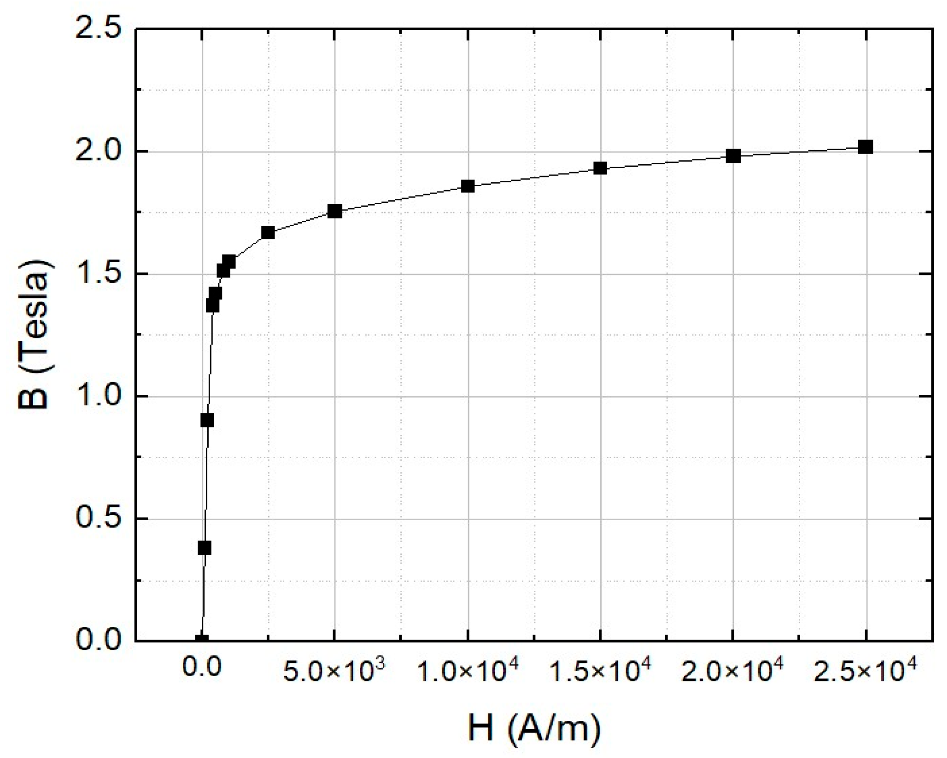
For the yoke material, the SPSII booster employs laminated steel magnets to minimize energy loss resulting when changing the magnetic fields during operation. Low-carbon–silicon electrical steel lamination of the Thyssenkrupp type is chosen as the laminated core material for nonlinear material properties of the magnet yoke with the isotropic property assumption; see Figure 3 for the B-H curve. In the simulation, a total potential type with a ‘Quadratic’ element was selected. For the magnet yoke, a suitable element size of 5 mm was chosen, acknowledging that while smaller sizes provide better precision, they also entail longer computational times.
The coil is constructed from copper and features a square profile measuring 7.5 × 7.5 mm2, incorporating a coolant hole with a diameter of 4 mm. The coil consists of 14 turns arranged in 2 layers, each with 7 turns. The thickness of the coil has been carefully chosen to facilitate easy assembly, ensuring it fits snugly into the pole profile with a fixed pole configuration. Each coil is electrically connected in a series, so the four coils carry the same electric current. The current density is 5.34 A/mm2. The calculated operating current of the magnet is 300 A for the quadrupole gradient of 19.395 T/m and the sextupole field of 22.327 T/m2. The parameters for the magnet prototype are listed in Table 2.

3.3. Air Regions Defined in Opera-3D for Magnetic Field Simulation

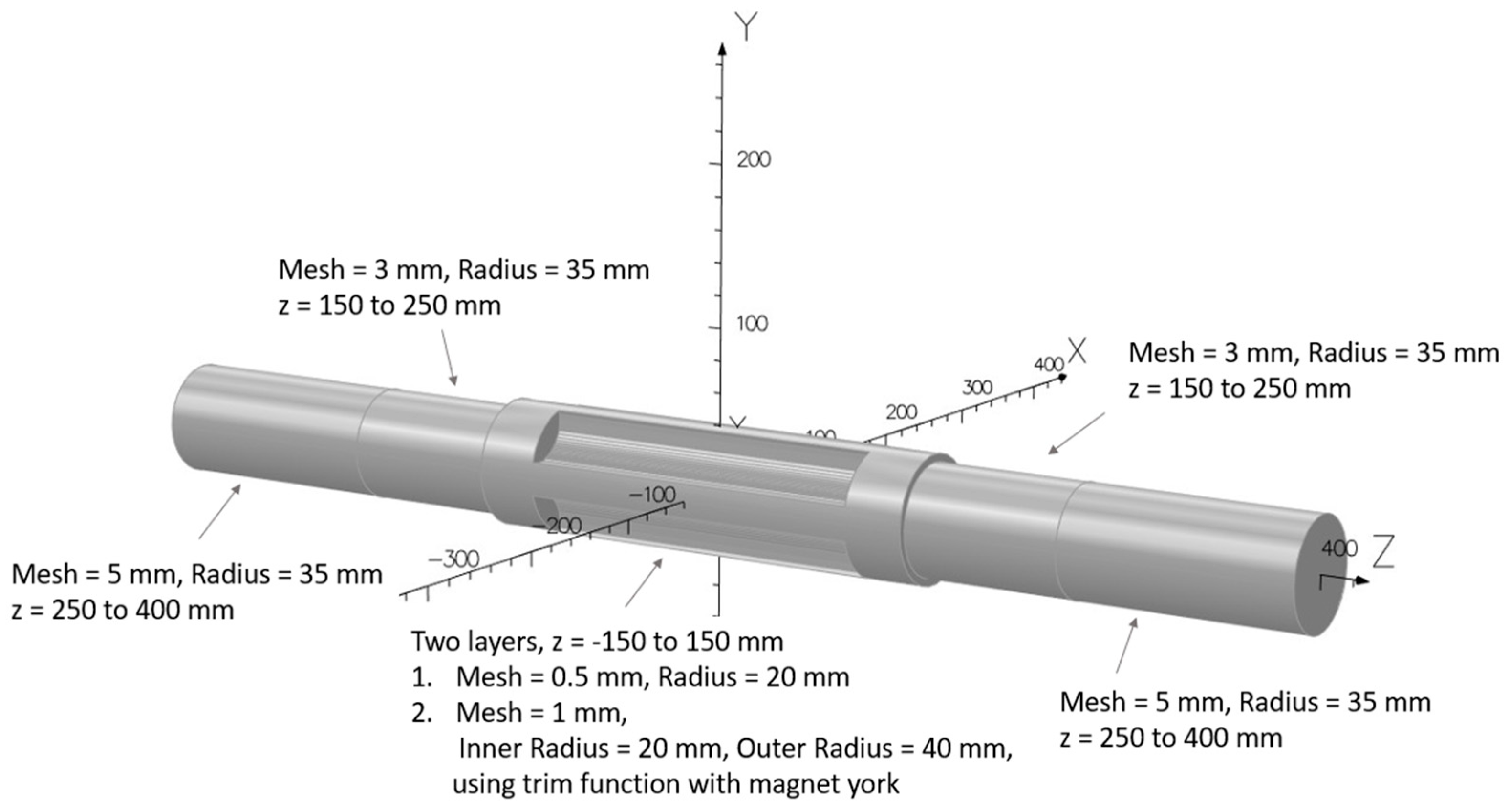
To perform magnetic field simulations using Opera-3D, it is necessary to configure the air condition. Optimal accuracy in the magnetic field simulation is achieved with a smaller mesh size for the air; however, this comes at the cost of longer running times. Therefore, it is crucial to strike a balance and optimize the mesh size. The air region is configured in the shape of a cylindrical structure, encompassing the specific area from which we intend to collect magnetic field data. In the case of the combined-quadrupole magnet, the mesh size is divided into four layers, detailed in Figure 4. In this case, the smallest mesh of 0.5 mm is positioned at the center of the magnet, utilizing data for the GFR and harmonic analysis. In the air region overlapping with the yoke, a mesh size of 1 mm is set. For improved accuracy, the cell properties of the air region are configured using the ‘Quadratic’ element type.

3.4. Analysis Setting for Magnetic Field Simulation

The analysis is conducted using a Magnetostatic Model with nonlinear magnetic materials and a Newton–Raphson iterative solver. For the combined-quadrupole magnet, the asymmetry between the left and right poles necessitates careful treatment in the simulation model. Reflection symmetry is applied, with tangential magnetic field boundary conditions imposed on the xy plane and normal magnetic field boundary conditions applied on both the xy and zx planes. Therefore, only one-quarter of the geometry was modeled to reduce computational time and resource usage during the simulation. The surface mesh is generated using the ‘Prefer Tetrahedral’ option with a size of 20 mm to accurately capture the geometric details. The volume mesh is employed with an ‘absolute tolerance used to test point coincidence’ set at 1 × 10⁻⁶.

3.5. Eddy Current Effect

During energy ramping in a booster synchrotron, the time-varying magnetic fields of the magnets induce eddy currents within the magnet yoke, coils, and nearby conductive structures, such as the vacuum chamber [13]. These eddy currents can affect both the magnetic field quality and the thermal load of the system, especially in the dipole magnet. But, for the quadrupole magnet, the eddy current effects are generally less pronounced in the main quadrupole field component. However, during ramping, the transient response can still introduce distortion.
To evaluate the performance of the booster synchrotron magnets during energy ramping, a time-dependent magnetic field simulation was performed using the Transient Electromagnetic solver in Opera-3D. The booster operates in a repetitive 2 Hz cycle, during which the magnetic field must track rapid changes in beam energy. To mitigate eddy current effects during booster ramping, laminated steel yokes with insulated layers are used to limit core currents, and smooth ramp waveforms are applied to reduce rapid field changes. The vacuum chamber is made from conductive materials like stainless steel with optimized wall thickness to minimize induced currents.
During ramping up to 3 GeV, a modified sinusoidal waveform, as described in Ref. [14], was used to model the excitation current, simulating realistic ramping conditions. In the simulation, the magnet yoke was modeled using linear magnetic properties with a relative permeability of 3048. Neglecting hysteresis effects is an acceptable approximation when the magnetic field remains within a range where the material behaves approximately linearly. To account for the mitigation of eddy currents, an anisotropic lamination model was implemented with a packing factor of 0.95, representing the effect of laminated steel structures. The electrical conductivity of the yoke was treated as anisotropic, specified as 4348 S/mm within the lamination plane (xy-plane) and 0 S/mm along the stacking direction (z-axis). A 316LN stainless steel vacuum chamber was also incorporated into the model to evaluate eddy currents induced by the time-varying magnetic field. The chamber was modeled with an isotropic electrical conductivity of 1351 S/mm, a relative magnetic permeability of 1.02, and a wall thickness of 0.75 mm in order to minimize multipole field errors.
To reduce computational time, the simulation focused exclusively on the energy ramp-up phase, with the magnetic field ramped from 0 s to 0.25 s in increments of 0.05 s. This comprehensive simulation setup provides valuable insight into eddy current distribution and magnetic field dynamics, ensuring robust magnet performance under real booster operating conditions.

4. Magnet Prototype

4.1. Prototype Manufacturing

Prototype magnets for the SPS-II booster synchrotron were developed collaboratively by the Synchrotron Light Research Institute (SLRI) and a local manufacturer in Thailand. The magnet yokes were fabricated from CSC 50CS1300 laminated silicon steel, sourced from China Steel Corporation, Hsiao Kang, Kaohsiung 81233, Republic of China (Taiwan), chosen for its superior magnetic properties, such as low hysteresis and minimized eddy current losses. Each lamination sheet is 0.5 mm thick and features a 0.6 µm insulating coating on both sides to further suppress interlaminar eddy currents.
To achieve high magnetic field quality and tight dimensional control at the pole tips, the yoke laminations were precision-cut using the Wire-Cut Electrical Discharge Machining (EDM) method, which enabled a fabrication and assembly tolerance of ±25 µm at the magnet poles. Less stringent mechanical tolerances were applied in non-critical areas to streamline fabrication and reduce costs. Prior to EDM machining, the silicon steel sheets were edge-welded to preserve alignment. Following profiling, the laminations were stacked using custom fixtures that ensured precise alignment and uniform compression. For quadrupole magnets, the laminated cores were secured using insulated bolts and washers to avoid interlayer electrical shorts. Cover plates were welded along the outer edges of the yoke to enhance mechanical rigidity and dimensional stability. Notably, no adhesives or bonding agents were used during the assembly.
As shown in Figure 5, the prototype features a combined-quadrupole magnet. The yoke was designed in two symmetrical halves (upper and lower) to ease the installation of magnet coils and the vacuum chamber within the tunnel. To accommodate coil insertion without the need for pole disassembly, the magnet poles were angled at 65 degrees relative to the x-axis. This design choice, combined with the non-removable, integrated pole tips, necessitated a carefully optimized coil geometry that ensures adequate clearance during assembly while maintaining the required mechanical integrity and magnetic performance.

4.2. Magnetic Field Measurement System

The magnetic field was measured using the Hall-probe technique, as shown in Figure 6. A Lake Shore three-axis Hall probe, in conjunction with a Model 460 Gaussmeter (Lake Shore Cryotronics, Westerville, OH 43082, USA) [15], was employed for the measurements. The system offers a measurement accuracy of ±0.25% of the reading for magnetic fields up to 2 T under controlled environmental conditions, typically maintained at 25 °C. The three-axis probe enables simultaneous measurement of all field components (Bx, By, Bz), ensuring reliable vector field characterization. Figure 6 illustrates the Hall-probe measurement setup, including the probe mounting configuration and positioning system. To address probe positional discrepancies, a centering procedure was performed prior to the magnetic field measurements to accurately determine the position of the Hall probe. This procedure involved scanning the probe along both the horizontal (x) and vertical (y) axes to locate the magnetic center of the vertical magnetic field. Based on this method, we are confident that the Hall probe was well-centered during the measurements.
Due to limitations of the DC power supply, the maximum current achievable during the measurement campaign was limited to 210 A, which is below the magnet’s nominal operating current of 300 A. As a result, the magnetic field data acquired at 210 A provide an approximation of the expected field behavior under nominal operating conditions. The measurements were conducted over a horizontal range of −20 mm to 20 mm to comprehensively capture the magnetic field characteristics within the designated GFR, while y and z coordinates were set at the center. For multipole analysis, the magnetic field was measured by scanning the azimuthal angle from 0° to 360° in 5° increments at a reference radius of 4 mm.

5. Results and Discussion

5.1. Mechanical Analysis

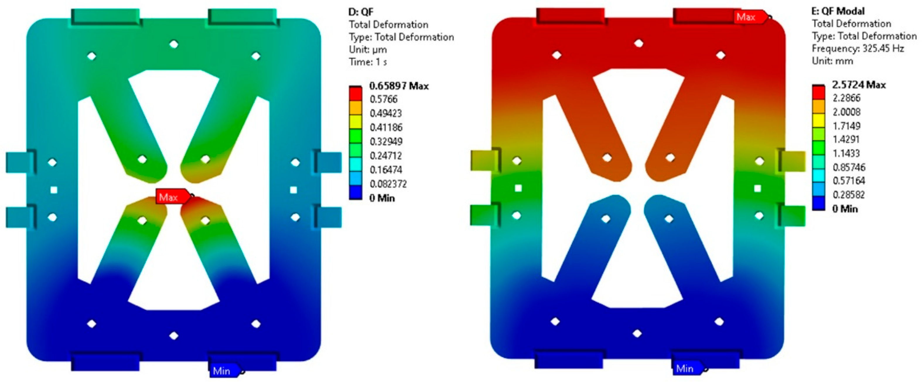
Figure 7 shows the results of the mechanical analysis, illustrating the magnet’s static deformation caused by the combined effects of magnetic forces and coil weight, as well as the total deformation obtained from the modal analysis. The simulation results indicate that the static deformation of the magnet structure is at 0.7 μm, which is well within acceptable limits for maintaining the required field quality. Additionally, the first-mode natural frequency of the structure was determined to be 325 Hz, which is sufficiently high to avoid resonance with operational frequencies and external vibrations that could impact magnet performance. These results confirm that the prototype magnet design is robust, with structural deformations and vibrational modes that are compatible with the operational requirements. Further optimization of the mechanical design may involve refining the support structure, enhancing the rigidity of the magnet assembly, and ensuring that all components are within acceptable stress and deformation limits.

5.2. Eddy Effect

Figure 8 shows the simulated surface current density distribution obtained using Opera-3D at 0.25 s, corresponding to a beam energy of 3.0 GeV. The results indicate that eddy currents are primarily confined within the lamination planes, with peak concentrations near the magnet ends. The maximum current density, reaching 0.0442 A/mm2 at the pole tip, leads to localized power losses within the laminated steel yoke.
Transient simulations further reveal that eddy currents can reduce the quadrupole gradient by approximately 1%, while the sextupole component may increase by up to 5% compared to the case without eddy current effects. This results in an increase in higher-order multipole components, which can adversely affect beam dynamics by causing tune shifts and reducing the dynamic aperture of the booster lattice. However, these effects may be mitigated through the optimization of standalone sextupole magnets.
The results showing the minimal impact of eddy currents clearly indicate that eddy current effects can be negligible under steady-state conditions. Consequently, the use of a DC power supply is sufficient during magnetic field measurements.

5.3. Magnetic Field of Combined-Function Quadrupole-Sextupole Magnet

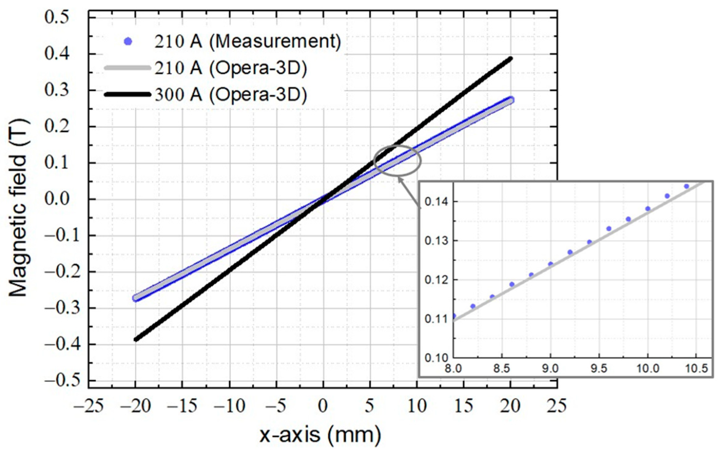
Figure 9 shows the vertical magnetic field component (By) as a function of the horizontal position (x-direction) at the magnet’s mid-plane, defined by y = z = 0. A comparison between the calculated and measured fields at a current of 210 A demonstrates good agreement. The simulation and measurement results closely match and appear nearly indistinguishable in the figure. The field difference between the two data sets is approximately 1%, which can be attributed to the resolution limit of the Hall probe. Although measurements at 300 A could not be performed, the strong agreement observed at 210 A suggests that similarly accurate results can be expected at higher current levels.
Regarding the magnet length, although the lattice design specifies an effective magnetic length of 250 mm, the physical length of the magnet yoke can be shorter due to the contribution of fringe fields [8]. The effective magnetic length was evaluated by integrating the longitudinal magnetic field component along the beam axis and normalizing by the peak field value, following the formula ∫Bydz/By(z = 0). Based on this analysis, the physical length of the combined-function quadrupole magnet was determined to be 223.5 mm, approximately 10% shorter than the effective length. The magnetic field profile along the z-axis, as shown in Figure 10, was used to estimate the effective length. Magnetic fields were carried out 10 mm along the x-axis at the center of the y-axis. The vertical magnetic field data from simulation and measurement show good agreement at the magnet center; however, a larger deviation is observed near the end of the pole. This variation results in a difference in the effective length between simulation and measurement. It was found that the simulated effective length is approximately 250 mm, whereas the measured effective length is about 0.8% greater than the simulation.
For magnetic field gradient analysis, the gradients of the quadrupole and sextupole fields were extracted from the vertical magnetic field distribution By(x) by fitting a sixth-order polynomial within the GFR requirement, defined from −15 mm to +15 mm on the x-axis. The polynomial fitting to the multipole field expansion can be expressed by
B y x = B 0 + B 1 x + 1 / 2 B 2 x 2 + 1 / 6 B 3 x 3 + ,
where By(x) is the magnetic field along the x-axis. The coefficients B0, B1, and B2 represent the dipole field, quadrupole gradient, and sextupole gradient, respectively.
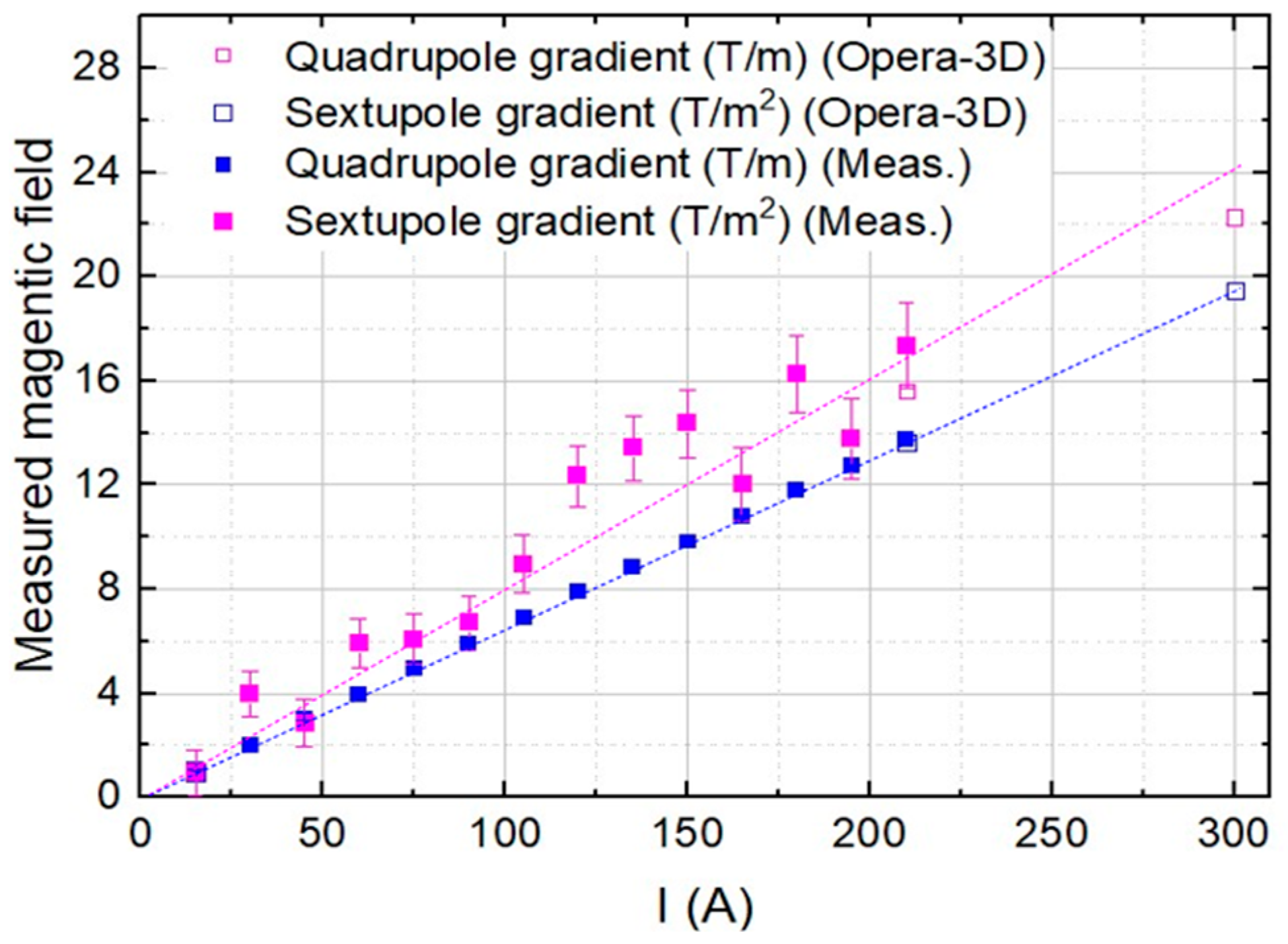
Figure 11 shows the quadrupole and sextupole gradients extracted from Hall-probe measurements. The quadrupole component, corresponding to the linear term in the polynomial fit, demonstrates good agreement with the simulation results, with measured values approximately 1% higher than predicted. In contrast, the analysis of sextupole gradients from the field measurements exhibits greater variation. A linear fit of the sextupole field versus the applied current reveals that the measured sextupole component is approximately 10% higher than the value predicted by simulation, as summarized in Table 3. The larger deviation may be attributed to factors such as mechanical misalignments, probe positioning errors, inherent noise in the measurement process, or the selected order of polynomial fitting. To improve the accuracy in evaluating the sextupole component, a multipole analysis based on the measured magnetic field data will be carried out, as presented in the following section.
For a combined-function quadrupole magnet, it is essential to minimize the presence of unwanted higher-order multipole components that can adversely affect beam dynamics. This can be assessed through the normalized error distribution, defined as the magnetic field profile scaled with respect to the reference components up to the sextupole term, as expressed in the equation below. In the simulation, the normalized gradient error must be below 1 × 10⁻³ within the GFR of ±15 mm. The normalized gradient field error at the mid-plane (y = z = 0) can be calculated and expressed using the polynomial expansion shown in the equation below [16]:
B / B = B y x B 0 + B 1 x + 1 / 2 B 2 x 2 / B y x ,
where By(x) is the vertical magnetic field along the x-axis. The coefficients of B0, B1, and B2 obtained from polynomial fitting correspond to the dipole field, quadrupole gradient, and sextupole gradient, respectively.
Figure 12 presents the normalized magnetic field distributions obtained from both simulation and measurement. Within the GFR, the average values show good agreement between the two, although the measured data exhibit slightly larger fluctuations. However, with prototype measurement on the right-hand side, the measured field is consistently higher than the simulated values. While some deviation can be attributed to the inherent limitations of the Hall probe, including its accuracy and resolution, the primary source of discrepancy is believed to be a mechanical misalignment between the upper and lower poles, which likely affects the local magnetic field in that region.
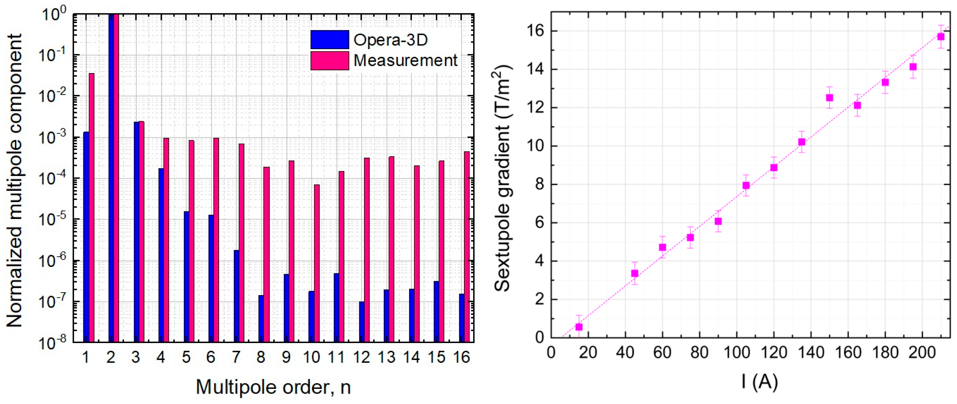
To ensure the magnetic field quality of the magnet, all multipole errors are maintained below 1 × 10⁻³. In this study, multipole analysis was performed using both Opera-3D simulations and Hall-probe measurements within a circular region of 4 mm radius from the magnet center (z = 0). The probe was rotated from 0° to 360° in 5° steps, with the horizontal and vertical coordinates adjusted simultaneously at each angular position to maintain a constant radius. The multipole components were extracted using Fourier series fitting [17]. The normalized magnetic field error is defined relative to the main quadrupole component (n = 2), allowing higher-order multipole errors to be expressed as a fraction of the primary quadrupole field. Accordingly, the main quadrupole component (n = 2) was used as the reference for calculating the normalized field error. Figure 13 (left) presents a comparison of the normalized normal multipole components at an excitation current of 210 A, as obtained from both simulation and measurements. For the dipole term and higher-order components (n = 4, 5, 6, …), the measured multipole strengths tend to exceed the simulated values. The measured deviation is likely due to mechanical misalignments of the magnet poles, which can introduce field distortions. Any residual misalignment is expected to manifest primarily as a dipole component rather than as higher-order multipoles. Higher-order field errors can be further minimized by chamfering the ends of the magnet poles [8]. In the actual machine, the dipole term affecting the beam orbit in the booster can be corrected by applying appropriate magnetic fields using the corrector magnets.
To further assess the magnetic field quality and mitigate potential measurement uncertainties related to probe positioning, additional verification using the stretched-wire method is planned [18,19]. If the magnetic field errors are found to originate from the magnet itself, pole chamfering will be considered to reduce the higher-order field errors.
Figure 13 (right) presents the sextupole gradient obtained from the multipole analysis. The result shows good agreement with the simulation and demonstrates improved linearity compared to that obtained by fitting the magnetic field along the x-axis, as previously discussed. This measurement technique confirms the precision and reliability in accurately determining the sextupole component.

6. Conclusions

A prototype of the combined-function quadrupole-sextupole magnet for the SPS-II booster was successfully developed and fabricated in Thailand, marking an important milestone in the domestic advancement of accelerator technology. The prototype, featuring a laminated yoke, demonstrated that local manufacturing can meet the required specifications and tolerances. The magnetic field measurements showed good agreement with the simulation results, confirming both the accuracy of the magnet design and the reliability of the simulation and analysis methods. Additionally, the development and testing of this prototype provided valuable insights into areas that require further improvement in future magnet designs.
Although the most recent SPS-II booster design has replaced the combined-function quadrupole magnet with a pure quadrupole magnet to provide greater flexibility in magnetic field tuning and to reduce multipole field errors, the comparison results will be reported elsewhere. Nevertheless, the experience gained from this prototype remains valuable. The successful development of the prototype validates the overall design approach and confirms that domestic manufacturing is capable of supporting the SPS-II project. This achievement contributes to the long-term sustainability and self-reliance of accelerator technology development in Thailand.

Author Contributions

S.J. conceived the concept and methodology, performed the design and simulations, and analyzed the results. P.S. (Prapaiwan Sunwong) co-conceived the concept and methodology, provided guidance on the simulations, and contributed to the discussion of the measurement results. S.P. co-developed the concept and methodology and was responsible for setting up the measurement system. T.L. conducted the mechanical analysis. P.N. and N.T. performed field measurements and discussed the results. The research was conducted under the supervision of P.S. (Porntip Sudmuang), and the manuscript was written by S.J. All authors have read and agreed to the published version of the manuscript.

Funding

This research was funded by the Science, Research, and Innovation Fund (SRI fund), Thailand.

Data Availability Statement

The data supporting the findings of this study are available from the corresponding author upon request.

Acknowledgments

The authors would like to thank NSRRC for their support and valuable suggestions on the magnet design, magnetic field measurements, and data analysis.

Conflicts of Interest

The authors declare no conflicts of interest.

References

  1. Klysubun, P.; Pulampong, T.; Sudmuang, P. Design and optimization of SPS-II storage ring. In Proceedings of the 8th International Particle Accelerator Conference (IPAC 2017), Copenhagen, Denmark, 14–19 May 2017; pp. 2773–2775. [Google Scholar] [CrossRef]
  2. Klysubu, P.; Boonsuya, S.; Chanwattana, T.; Jummunt, S.; Juntong, N.; Kwankasem, A.; Phimsen, T.; Photongkam, P.; Prawanta, S.; Pulampong, T.; et al. SPS-II: 4th-generation Synchrotron Light Source in Southeast Asia. In Proceedings of the 13th International Particle Accelerator Conference (IPAC 2022), Bangkok, Thailand, 12–17 June 2022; pp. 764–768. [Google Scholar] [CrossRef]
  3. Filho, A.H.C.; Rodrigues, A.R.D.; Farias, R.H.A.; Liu, L.R.; Carmo, D.; Nicolodi, C.; Junqueira, T.; Hojvat, C.; Sa, F.M. Commissioning Status of Sirius, the Brazilian 4th Generation Light Source. In Proceedings of the 12th International Particle Accelerator Conference (IPAC 2021), Campinas, Brazil, 24–28 May 2021; pp. 13–18. [Google Scholar] [CrossRef]
  4. Kuo, C.C.; Chen, C.T.; Chen, J.Y.; Chiu, M.S.; Chou, P.J.; Hsu, K.T.; Liu, Y.C.; Luo, G.H.; Tsai, H.J.; Tseng, F.H. Commissioning of the Taiwan Photon Source. In Proceedings of the IPAC’15, 6th International Particle Accelerator Conference, Richmond, VA, USA, 3–8 May 2015; Paper TUXC3. pp. 1314–1318. [Google Scholar] [CrossRef]
  5. Willeke, F.J. Commissioning of NSLS-II. In Proceedings of the 6th International Particle Accelerator Conference (IPAC’15), Richmond, VA, USA, 3–8 May 2015; Paper MOYGB3. pp. 15–20. [Google Scholar] [CrossRef]
  6. Streun, A. SLS 2.0, the Upgrade of the Swiss Light Source. In Proceedings of the 13th International Particle Accelerator Conference (IPAC’22), Bangkok, Thailand, 12–17 June 2022; Paper TUPOST032. pp. 925–928. [Google Scholar] [CrossRef]
  7. Krainara, S.; Klinkhieo, S.; Klysubun, P.; Pulampong, T.; Sudmuang, P. Conceptual Design of Booster Synchrotron for Siam Photon Source II. In Proceedings of the 12th International Particle Accelerator Conference (IPAC 2021), Campinas, Brazil, 24–28 May 2021; pp. 2795–2797. [Google Scholar]
  8. Tanabe, J. Iron Dominated Electromagnets: Design, Fabrication, Assembly and Measurements; World Scientific Publishing: Singapore, 2005; pp. 33–286. ISBN 9789813101982. [Google Scholar]
  9. Tatum, J. Rotation of Axes, Two Dimensions, Physics LibreTexts (Celestial Mechanics), Section 3.6, Updated March 5, 2022; CC BY-NC 4.0. Available online: https://phys.libretexts.org/Bookshelves/Astronomy__Cosmology/Celestial_Mechanics_(Tatum)/03%3A_Plane_and_Spherical_Trigonometry/3.06%3A_Rotation_of_Axes_Two_Dimensions (accessed on 27 June 2025).
  10. Wiedemann, H. Particle Accelerator Physics; Springer: Berlin/Heidelberg, Germany, 2007; pp. 37–112. ISBN 978-3-540-49043-2. [Google Scholar]
  11. Dassault Systèmes UK Ltd. Opera-3D, Release 2021, 18R2 Reference Manual; Dassault Systèmes UK Ltd.: Kidlington, UK, 2018; pp. 1–918. [Google Scholar]
  12. ANSYS®. Academic Research, Release 2022; ANSYS, Inc.: Canonsburg, PA, USA, 2022. [Google Scholar]
  13. Peng, Y.M.; Li, J.Y.; Meng, C.; Xu, H.S. Study of the ramping process for HEPS booster. In Proceedings of the 10th International Particle Accelerator Conference (IPAC’19), Melbourne, Australia, 19–24 May 2019; pp. 1521–1523. [Google Scholar] [CrossRef]
  14. Jummunt, S.; Sunwong, P.; Sudmuang, P.; Phimsen, T.; Klysubun, P. Design Progress of the Booster Synchrotron for Siam Photon Source II. In Proceedings of the 16th International Particle Accelerator Conference (IPAC 2025), Taipei, Taiwan, 1–6 June 2025; pp. 2004–2007. [Google Scholar] [CrossRef]
  15. Lake Shore Hall Probes. Available online: https://www.lakeshore.com/docs/default-source/product-downloads/catalog/hall-probes_l.pdf?sfvrsn=9e7b957d_6 (accessed on 1 June 2025).
  16. Kuo, C.Y.; Hwang, C.S.; Chang, C.H. Development of combined function magnets for the Taiwan photon source. In Proceedings of the 23rd Particle Accelerator Conference (PAC 2009), Vancouver, BC, Canada, 4–8 May 2009; pp. 202–204, MO6PFP030. [Google Scholar]
  17. Sunwong, P.; Prawanta, S.; Jummunt, S.; Numanoy, P.; Leetha, T.; Phimsen, T.; Pruekthaisong, P. Effects of Eddy Current and Permeability of Vacuum Chamber on Magnetic Field in Booster Synchrotron of Siam Photon Source II. J. Phys. Conf. Ser. 2025, 2934, 012013. [Google Scholar] [CrossRef]
  18. Chen, C.; Yang, C.; Yang, C.; Chen, H.; Huang, J. Integrated Hall probe and stretched wire measurement system for an in-vacuum undulator. In Proceedings of the 15th International Particle Accelerator Conference (IPAC 2025), Nashville, TN, USA, 19–24 May 2024; pp. 1398–1401. [Google Scholar] [CrossRef]
  19. Le Bec, G.; Chavanne, J.; Pennel, C. Stretched wire measurement of multipole accelerator magnets. Phys. Rev. Accel. Beams 2012, 15, 22401. [Google Scholar] [CrossRef]
Figure 1. Layout of 1/8 of SPS-II booster synchrotron [7].
Particles 08 00077 g001
Figure 2. (left) Magnet model using Opera-3D and (right) pole profile of combined-quadrupole magnet compared to pure quadrupole. The magnet yoke is shown in green, and the coils are highlighted in red.
Particles 08 00077 g002
Figure 3. B-H curve for Thyssenkrupp used as laminate steel.
Particles 08 00077 g003
Figure 4. Air condition for magnetic field simulation.
Particles 08 00077 g004
Figure 5. (left) Magnet pole during manufacturing and (right) prototype of a combined-function quadrupole-sextupole magnet.
Particles 08 00077 g005
Figure 6. (left) System of Hall-probe measurement and (right) Lake Shore three-axis Hall probe with Model 460 Gaussmeter.
Particles 08 00077 g006
Figure 7. (left) Static deformation and (right) total deformation from modal analysis.
Particles 08 00077 g007
Figure 8. Eddy current density calculated in Opera-3D at 300 A.
Particles 08 00077 g008
Figure 9. The vertical magnetic field along the x-axis (y = z = 0). Blue symbols denote the measured magnetic field using the Hall-probe technique. Gray and black symbols represent the magnetic field calculated using Opera-3D for coil currents of 210 A and 300 A, respectively.
Particles 08 00077 g009
Figure 10. The vertical magnetic field along the z-axis (x = 10 mm, y = 0). Blue symbols denote the measured magnetic field using the Hall-probe technique. Gray and black symbols represent the magnetic field calculated using Opera-3D for coil currents of 210 A and 300 A, respectively.
Particles 08 00077 g010
Figure 11. The excitation curve obtained from measurements over the current range from 15 A to 210 A. Open symbols represent the magnetic field calculated using Opera-3D. Solid symbols represent the measured magnetic field using the Hall-probe technique.
Particles 08 00077 g011
Figure 12. Normalized magnetic field error along the x-axis at the current of 210 A. Blue symbols represent the magnetic field calculated using Opera-3D. Pink symbols represent the measured magnetic field using the Hall-probe technique.
Particles 08 00077 g012
Figure 13. (left) Normalized normal multipole at the current of 210 A and (right) sextupole gradient from multipole analysis.
Particles 08 00077 g013
Table 1. Design parameters of booster magnets.
Design ParametersBDQFQDSF/SD
Effective length (m)1.50.250.20.2
Number of magnets40401616/16
Dipole field (T)1.048000
Quadrupole field (T/m)−2.08419.395−0.70745
Sextupole field (T/m2)−29.99522.3270167.483/−136.389
Good Field Region (GFR) (mm)±10±15±15±18
Field homogeneity 1 × 10−41 × 10−35 × 10−45 × 10−4
Table 2. Parameters of combined-quadrupole magnet.
ParametersValue
Effective length 250 mm
Physical length 223.5 mm
Current excitation 4890.38 A-turns
Operating current 300 A
Number of turns14 turns
Conductor size7.5 mm × 7.5 mm
Bore radius23 mm (pole left), 23.153 mm (pole right)
Table 3. Multipole components at the applied current of 210 A.
Multipole FieldOpera-3DHall-Probe Measurement
B0 (T)0.00010.0001 ± ---
B1 (T/m)13.639113.7320 ± 0.008
B2 (T/m2)15.617117.3266 ± 1.647
Disclaimer/Publisher’s Note: The statements, opinions and data contained in all publications are solely those of the individual author(s) and contributor(s) and not of MDPI and/or the editor(s). MDPI and/or the editor(s) disclaim responsibility for any injury to people or property resulting from any ideas, methods, instructions or products referred to in the content.