Abstract
Off-road vehicle control designs often neglect the complex tire–soil interactions inherent to soft terrain. This paper proposes a Variable Impedance Control (VIC) strategy integrated with a high-fidelity terramechanics model. First, a real-time sinkage estimation algorithm is derived using experimentally identified Bekker parameters and the quasi-rigid wheel assumption to capture the nonlinear feedback between soil deformation and vehicle dynamics. Building on this, the VIC strategy adaptively regulates virtual stiffness, damping, and inertia parameters based on real-time suspension states. Comparative simulations on an ISO Class-C soft soil profile demonstrate that this framework effectively balances ride comfort and safety constraints. Specifically, the VIC strategy reduces the root-mean-square of vertical body acceleration by 46.9% compared to the passive baseline, significantly outperforming the Linear Quadratic Regulator (LQR). Furthermore, it achieves a 48.6% reduction in average power relative to LQR while maintaining suspension deflection strictly within the safe range. Moreover, unlike LQR, the VIC strategy improves tire deflection performance, ensuring superior ground adhesion. These results validate the method’s robustness and energy efficiency for off-road applications.
1. Introduction
Off-road vehicles are pivotal platforms for military operations, modern agriculture, planetary exploration, and resource extraction [1]. Unlike conventional on-road vehicles, these platforms operate on unstructured soft terrain—such as sand, snow, and mud—where mobility is dominated by complex terramechanical interactions characterized by significant sinkage, slip, and nonlinearity [2]. These harsh environments impose severe low-frequency excitations that not only impair occupant health and sensitive equipment but also compromise handling stability and road-holding capabilities, thereby exacerbating the rollover risk for high-center-of-gravity vehicles [3,4]. While passive suspensions are constrained by an inherent trade-off between ride comfort and safety due to fixed parameters, and semi-active systems offer limited bandwidth, Active Suspension Systems (ASS) have emerged as a superior solution [5]. By leveraging actuators to generate precise control forces, ASS can theoretically decouple conflicting performance objectives and adapt to the extreme parameter uncertainties and nonlinearities inherent in off-road dynamics [6].
To fully exploit the capabilities of ASS, advanced control algorithms are essential. Modern control paradigms—ranging from PID [7,8] and Sliding Mode Control [9] to methods [10] and intelligent optimization [11]—have demonstrated remarkable success in enhancing ride quality and stability on standard rigid pavements. However, the efficacy of these algorithms is predominantly predicated on the “rigid road” assumption, which simplifies tire–road interaction to geometric contact while neglecting substrate deformation. This assumption is rendered invalid in off-road environments governed by terramechanics [12,13], where wheel loads induce significant plastic sinkage in soft soil [14]. This sinkage phenomenon introduces two critical effects: it alters the effective road profile excitation and acts as a complex form of external damping via nonlinear energy dissipation [15]. Consequently, conventional controllers that neglect this tire–soil interaction suffer from severe model mismatch and performance degradation. Although terramechanics-based modeling is well-established in planetary rover robotics [16,17], it remains largely unintegrated into active suspension strategies for conventional off-road vehicles. This discrepancy highlights an urgent need for control frameworks that explicitly account for deformable terrain dynamics.
Nevertheless, the practical implementation of such terramechanics-based frameworks is contingent upon accurate parameter identification, which is fundamental to correcting and optimizing off-road vehicle dynamics [18]. While the Bekker model serves as the classical theoretical framework for the pressure–sinkage relationship, its governing parameters—specifically the cohesive modulus , friction modulus , and sinkage exponent n—exhibit high nonlinearity and sensitivity to soil types [19]. Consequently, the direct adoption of generic empirical data from the literature fails to meet the precision requirements of high-fidelity simulations. To bridge this gap, specific soil parameter identification via experimental apparatuses like the Bevameter is indispensable [20]. By coupling experimental data with advanced numerical inversion algorithms, such as Genetic Algorithms [21], the Newton–Raphson method [22] or Weighted Least Squares (WLS) [23], accurate parameter estimation can be achieved, establishing a robust foundation for predicting vehicle performance on deformable terrain [24].
Building upon the high-fidelity interaction model, the focus shifts to the control architecture. In such extreme and rapidly time-varying environments, traditional control strategies with fixed gains are inadequate; they enforce a rigid trade-off where a “stiff” setting severely compromises ride comfort, while a “soft” setting risks suspension bottoming. While adaptive control strategies such as Model Reference Adaptive Control (MRAC) are effective for handling parameter uncertainties [25], they are typically formulated to enforce the system output to follow a prescribed reference model trajectory. In deformable terrain, strictly enforcing such tracking can induce excessive tire–soil interaction forces and increase sinkage as the terrain yields. Therefore, instead of enforcing strict reference-model tracking, this study adopts Impedance Control to regulate the dynamic compliance of the vehicle–terrain interaction. Originally formalized by Hogan for regulating the dynamic interaction between a manipulator and its environment, this approach offers a robust theoretical framework [26,27]. While this paradigm has been extensively validated in robotics [28,29], rehabilitation [30,31], and power systems [32,33], its application in vehicle suspensions remains under-explored. Recent studies have integrated impedance concepts with fuzzy logic [34] and optimization algorithms [35,36,37]. However, these approaches predominantly rely on fixed target impedance parameters optimized for rigid roads, rendering them ill-suited for the nonlinear sinkage of soft terrain. To resolve the inherent conflict between comfort and stroke constraints in off-road scenarios, this study proposes a Variable Impedance Control (VIC) strategy. By modulating the target virtual stiffness (), damping (), and inertia () online based on real-time feedback of suspension deflection and body acceleration, the system can adaptively balance energy absorption with attitude stability.
The main contributions of this paper are threefold. First, a robust data-driven identification framework for the Bekker model parameters () is established based on Bevameter experimental data. Specifically, a Weighted Least Squares (WLS) algorithm is formulated to mitigate linearization errors inherent in logarithmic transformations, thereby ensuring a high-fidelity constitutive description of tire–soil mechanics. Building on this foundation, a quarter-car active suspension model incorporating real-time terrain interaction is developed under the quasi-rigid wheel assumption. By explicitly defining the algebraic feedback loop between dynamic tire load and plastic soil sinkage, the proposed model effectively captures the nonlinear coupling effects and the characteristic loss of adhesion specific to soft terrain environments. Finally, a state-dependent VIC strategy is proposed, featuring nonlinear modulation laws for virtual mass, damping, and stiffness parameters (). This strategy dynamically adapts suspension impedance based on real-time vehicle states, successfully resolving the fundamental conflict between ride comfort optimization and suspension travel constraints, while demonstrating superior energy efficiency compared to the Linear Quadratic Regulator (LQR) benchmark.
The remainder of this paper is organized as follows: Section 2 details the experimental acquisition of soil pressure–sinkage data using a Bevameter and the identification of Bekker model parameters via the Weighted Least Squares method. Section 3 establishes the time-domain road excitation model and formulates the coupled quarter-car dynamic model incorporating real-time sinkage estimation based on the quasi-rigid wheel assumption. Section 4 proposes the VIC strategy, deriving the nonlinear tuning laws for the virtual mass, damping, and stiffness parameters. Section 5 presents the simulation results and discusses the performance of the proposed controller under various off-road conditions. Finally, Section 6 concludes the paper with a summary of key findings and future work.
2. Soil Parameter Identification
Precise characterization of tire–soil interaction is fundamental to the study of active suspension control for vehicles operating on soft terrain. The pressure–sinkage characteristic serves as a key indicator of soil mechanical behavior, describing the nonlinear constitutive relationship between normal pressure and surface sinkage. Within the context of terramechanics, this characteristic is typically quantified using a Bevameter, the schematic configuration of which is illustrated in Figure 1. Specifically, plate-sinkage tests were conducted by controlling the vertical penetration of two rigid circular plates of different sizes into the soil substrate. High-precision force and displacement sensors were utilized to synchronously acquire real-time data regarding vertical load and sinkage displacement.
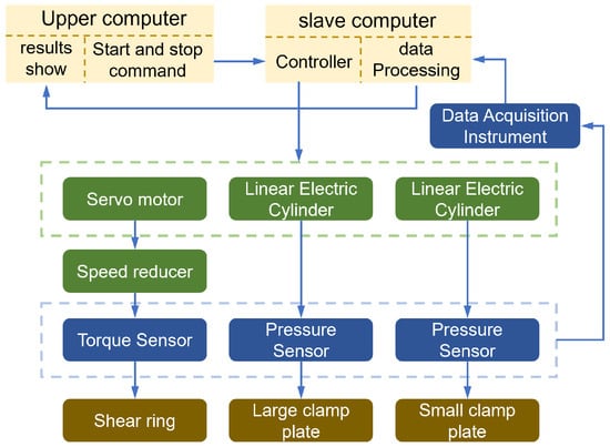
Figure 1.
Schematic diagram of the Bevameter system composition.
Following data acquisition, numerical fitting methods were employed to identify key mechanical parameters. These parameters facilitate the construction of high-fidelity tire–soil pressure and shear models, providing essential data support for subsequent dynamic simulations. Figure 2 presents the raw experimental curves of soil pressure–sinkage characteristics obtained via the Bevameter.
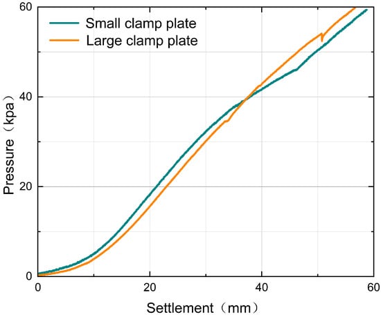
Figure 2.
Soil load–sinkage data.
As observed in Figure 2, the experimentally measured soil pressure and sinkage data exhibit a characteristic nonlinear progression. As the sinkage depth increases, the soil reaction force rises exponentially. Furthermore, significant discrepancies exist between the response curves of plates with distinct dimensions, indicating that the pressure–sinkage characteristic depends not only on the intrinsic physical properties of the soil but also on the contact geometry. To integrate this complex physical behavior into the suspension control architecture, a robust parametric characterization is indispensable.
For homogeneous soil, the pressure–sinkage relationship is widely described by the semi-empirical Bekker model:
where denotes the normal contact pressure; z is the sinkage depth; b represents the characteristic dimension of the contact patch (specifically, the radius for a circular area or the width for a rectangular one); n is the sinkage exponent indicating the soil’s sensitivity to deformation; and and represent the cohesive and frictional moduli of the soil, respectively. These parameters constitute the fundamental basis for describing the pressure–sinkage mechanics.
To robustly identify the parameters n, , and from the discrete measurement data shown in Figure 2, this study employed the WLS method. First, the Bekker model is linearized via logarithmic transformation:
Defining an equivalent stiffness coefficient , the equation simplifies to a linear form. However, applying the Ordinary Least Squares method directly to the linearized data is statistically suboptimal. The logarithmic transformation induces heteroscedasticity, where the variance of the transformed error becomes inversely proportional to the square of the pressure (). This results in a disproportionate amplification of errors in the low-pressure regime. To mitigate this logarithmic distortion and obtain a Best Linear Unbiased Estimator, a weighting strategy is essential. Following the methodology proposed in [23], the weighting factor is defined as to counterbalance the variance shift. The weighted objective function Q is thus formulated as:
Minimization of the fitting error involves computing the partial derivatives of Q with respect to n and K and equating them to zero, yielding the following normal equations:
Simultaneous solution of the derived normal equations yields the analytical expressions for the parameter estimates of a single plate dataset:
In experimental practice, the sinkage exponent n calculated from data obtained using two plates of different dimensions (radii and ) often exhibits numerical discrepancies. To improve the model’s generalizability, the arithmetic mean of the two is adopted as the final sinkage exponent . Consequently, the equivalent stiffness coefficients are re-evaluated using this consolidated :
Subsequently, by substituting the re-evaluated and into the definition of K, the following system of equations is established:
Solving this system yields the soil characteristic parameters and :
The proposed WLS algorithm was implemented within the MATLAB environment to process the pressure–sinkage data. The experimental soil is classified as Firm Sandy Clay Loam, with moisture content controlled at approximately 19% (by weight). This specific range ensures the soil maintains high shear strength without exhibiting the plastic fluid behavior typical of higher moisture levels. The identified key soil parameters (n, , and ) are listed in Table 1.

Table 1.
Identification results of Bekker model parameters.
As summarized in Table 1, the identified parameters reflect the distinct mechanical behavior of the test soil. Notably, the sinkage exponent n is greater than 1 (), reflecting the strain-hardening nature of the pre-compacted firm terrain, as opposed to the loose state typical of dry sand. These identified parameters are incorporated into the subsequent dynamic model to validate the performance of the controller.
3. Active Suspension Dynamic Model Incorporating Road Sinkage
To simulate stochastic road roughness encountered in actual driving environments, a time-domain road excitation model is constructed using the filtered white noise method. In accordance with the International Organization for Standardization (ISO 8608) [38] and GB/T 7031-2005 [39], the Power Spectral Density (PSD), , of the road profile elevation is formulated as:
where n denotes the spatial frequency (); represents the reference spatial frequency, typically set to ; is the road roughness coefficient at the reference spatial frequency, which determines the road class; and p denotes the waviness index, which is commonly set to 2.
Based on the classification criteria defined by the aforementioned standards, road surfaces are categorized into four classes (A through D) according to their PSD values. Table 2 presents the characteristic parameters for the selected road classes utilized in this study.
Table 2.
Classification of Road Roughness.
To facilitate time-domain simulation, the spatial road profile must be transformed into a temporal excitation signal. Assuming a constant vehicle forward velocity v, a lower cutoff frequency is introduced to avoid the singularity where the PSD tends toward infinity as the frequency approaches zero. By applying the filtered white noise method based on random vibration theory, the first-order time-domain differential equation governing road roughness is formulated as:
where represents the time derivative of the vertical road profile input ; denotes the lower cutoff frequency, typically set to ; v denotes the vehicle forward velocity (); and represents a standard Gaussian white noise signal with zero mean and unit variance.
The derived first-order differential equation serves as the basis for the road input model within the simulation framework. Implementing this equation in Simulink allows for the synthesis of a stochastic time-domain road elevation profile for a specified road class (determined by ) and vehicle forward velocity.
To assess the fidelity of the road excitation model presented in Equation (13), numerical simulations were conducted within the MATLAB/Simulink environment. The simulation parameters were configured as follows: a standard Class C road (), a vehicle forward velocity of , and a lower cutoff frequency of .
The simulation results are presented in Figure 3. Figure 3a illustrates the generated time history of the random road roughness. To further validate the model’s spectral fidelity, the Power Spectral Density (PSD) of the generated time-domain signal was calculated and compared with the theoretical standard, as shown in Figure 3b. The simulated PSD curve aligns closely with the theoretical benchmark across the effective frequency bandwidth. This confirms that the model accurately reproduces the statistical characteristics of real road surfaces, thereby validating its suitability as the excitation source for subsequent active suspension simulations.
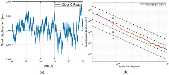
Figure 3.
Validation of the stochastic road excitation model. (a) Time-domain history of the road elevation profile generated for a standard Class C road at a vehicle speed of . (b) Comparison of the Power Spectral Density (PSD) between the simulated signal (red solid line) and the standard ISO 8608 road classification boundaries (dashed lines, labeled A–D), confirming the spectral fidelity of the generated Class C profile.
3.1. Sinkage Estimation Based on the Quasi-Rigid Wheel Assumption
The interaction between the wheel and soft terrain involves complex coupled mechanics. To facilitate real-time sinkage estimation, a simplified wheel–soil contact model is essential. In off-road conditions, the shear modulus and bearing stiffness of loose soil (e.g., sand or mud) are significantly lower than the vertical stiffness of a pneumatic tire. Consequently, the elastic deformation of the tire within the contact region is negligible compared to the plastic sinkage of the soil.
Building on this physical characteristic, this study adopts the “quasi-rigid Wheel” assumption, thereby neglecting the local flattening of the tire contact patch. Drawing upon classical terramechanics theory, a rigid wheel model is established to quantify the plastic soil deformation induced by the wheel load. It is worth noting that this assumption holds valid primarily when the terrain stiffness is significantly lower than the tire carcass stiffness, such as in loose sand or fresh snow. On firmer terrains where tire deflection becomes comparable to soil sinkage, a combined elastic-plastic model would be required. Therefore, the scope of this study is strictly limited to soft soil environments where the plastic sinkage dominates the wheel–terrain interaction.
Within the framework of the Bekker model, it is assumed that the radial pressure, , acting on the wheel surface is equivalent to the normal pressure, p, beneath a flat plate at the same depth (i.e., ). By incorporating this relationship, the vertical force equilibrium equation for a towed wheel is derived as follows:
where W denotes the vertical load acting on the wheel, b represents the tire width, r is the wheel radius, is the entry angle, and is the maximum sinkage depth.
Referring to the wheel–soil contact geometry illustrated in Figure 4, the wheel arc can be approximated as a parabola, provided that the sinkage remains small relative to the wheel diameter. The relationship between the horizontal coordinate, x, and the sinkage depth, z, satisfies:
where D represents the wheel diameter. Differentiating Equation (15) yields . Substituting this expression into Equation (14) transforms the domain of integration from x to z:
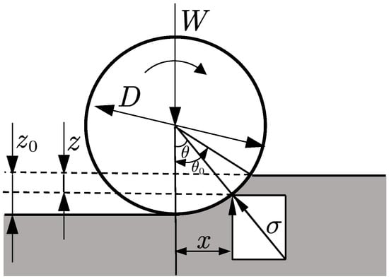
Figure 4.
Schematic diagram of the wheel–soil contact geometry based on the quasi-rigid wheel assumption. The arrows indicate the vertical load W, the direction of wheel rotation, geometric dimensions, and the normal stress .
To evaluate this integral, the variable substitution is introduced, yielding :
To derive a computationally efficient analytical solution suitable for the real-time control framework, the integrand is simplified. The binomial theorem is employed to expand the soil stress term , retaining only the first two terms. Following integration and rearrangement, the explicit formulation linking terrain sinkage to the vertical tire load W is obtained as:
Equation (18) demonstrates that sinkage is a nonlinear function of both the vertical load and soil parameters. This relationship allows for the estimation of road input excitations by explicitly accounting for the terrain’s plastic deformation.
3.2. Quarter-Car Active Suspension Model with Terrain Coupling
This section formulates a dynamic modeling framework to capture the interaction between off-road vehicles and deformable terrain. The primary objective is to quantify the coupling effects between soil plastic deformation and suspension dynamics.
Figure 5 illustrates the quarter-car model incorporating tire–terrain interaction. The system dynamics are defined within a coordinate frame where the vertical downward direction is positive. Distinct from traditional models on rigid surfaces, the effective road profile in this study is state-dependent, varying with the vehicle’s dynamic response.
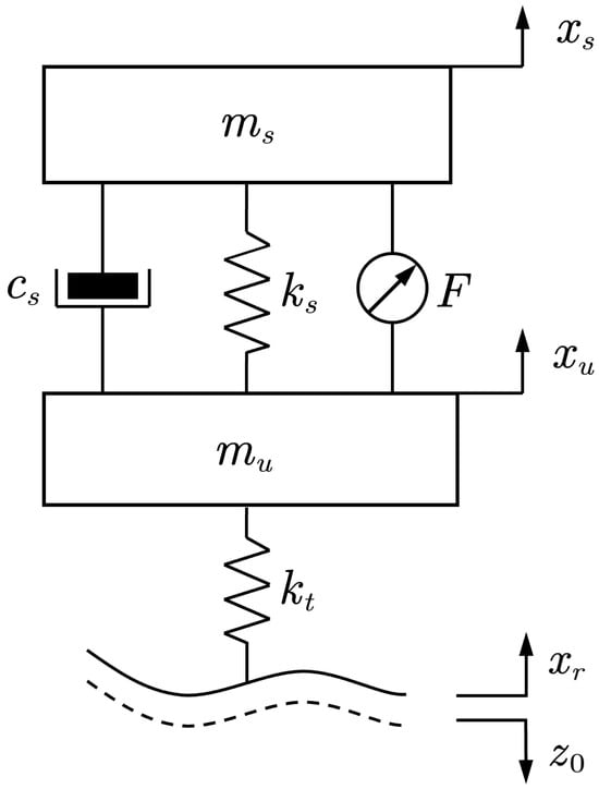
Figure 5.
Tire–terrain contact suspension model. The dashed line indicates the deformed terrain profile caused by soil sinkage ().
By applying Newton’s second law, the equations of motion for the sprung and unsprung masses are derived as follows:
where and represent the sprung and unsprung masses, respectively; and denote their vertical displacements; and are the suspension damping and stiffness coefficients; and F represents the active control force.
The vertical tire force (which acts as the load W in the sinkage model) is generated by the compression of the tire against the terrain. Defining the sinkage as a positive downward displacement of the ground surface, the effective road excitation becomes the superposition of the nominal road profile and the sinkage . The resulting tire force is is formulated as:
Here, represents the vertical tire stiffness, and the term represents the instantaneous vertical position of the terrain surface. As indicated by Equation (21), an increase in sinkage (indicating the terrain recedes downwards) reduces the net tire compression, thereby diminishing the vertical support force.
The interaction between Equations (18) and (21) establishes a nonlinear algebraic loop: the vertical load W determines the sinkage depth , which subsequently modifies the tire deflection, thereby modulating the contact force W. Consequently, the integrated system is formulated as a set of differential-algebraic equations (DAEs), requiring simultaneous solution at each simulation step to accurately predict the vehicle’s dynamic response on soft soil. For real-time implementation in an ECU, the aforementioned algebraic loop is resolved by introducing a unit delay. The sinkage depth from the previous time step is utilized to compute the current contact force. Given the high sampling frequency relative to the soil deformation dynamics, this approximation ensures deterministic computation time with negligible accuracy loss.
4. Variable Impedance Control Strategy
The fundamental principle of impedance control is to shape the dynamic relationship between force and motion, ensuring that the system exhibits prescribed dynamic characteristics when interacting with its environment. In the context of a quarter-car active suspension system, the sprung mass is modeled as the controlled plant, while its interaction with the unsprung mass and the road profile is treated as the “environmental” disturbance.
To formalize this interaction, an equivalent impedance model for the active suspension is illustrated in Figure 6. Assuming the desired system behavior follows second-order linear dynamics, the governing equation is formulated as:
where , , and represent the desired inertial mass, damping, and stiffness, respectively, and denotes the environmental contact force. The variable represents the position error, defined as the deviation of the actual displacement from the equilibrium position .
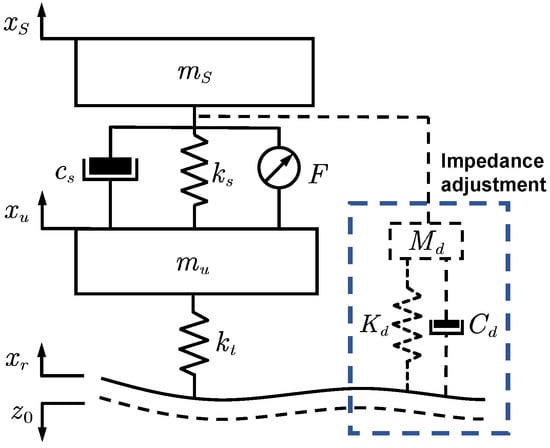
Figure 6.
Schematic of the quarter-car active suspension system based on variable impedance control. The dashed lines indicate the virtual impedance model and signal flow, while the bottom dashed line represents the deformed terrain profile.
To realize the target impedance defined in Equation (22), the control law is derived by integrating the actual suspension dynamics. Considering the plant equation (where F is the active control force), the required control input F is determined as:
Consequently, Equation (23) demonstrates that by systematically tuning the impedance parameters , , and , the dynamic response of the suspension system to external excitations can be explicitly modulated.
To establish effective tuning guidelines for the impedance parameters, a sensitivity analysis was conducted to investigate the sensitivity of vehicle performance to parameter variations. Specifically, the analysis focused on sprung mass acceleration, which serves as the primary metric for ride comfort, and suspension deflection, which reflects the constraints of suspension travel and safety. The admissible value ranges for these parameters are detailed in Table 3.
Table 3.
Impedance parameter ranges.
As illustrated in Figure 7, variations in the impedance stiffness have a negligible influence on the Root Mean Square (RMS) value of the sprung mass acceleration. In contrast, the RMS value of suspension deflection increases monotonically before reaching a plateau.
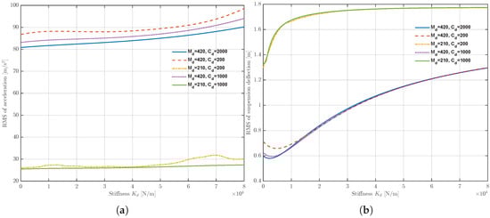
Figure 7.
Influence of the impedance stiffness on suspension performance metrics: (a) RMS of sprung mass acceleration. (b) RMS of suspension deflection.
Although impedance stiffness is instrumental in constraining suspension deflection, a fundamental trade-off exists with respect to ride comfort. Under large road excitations—where significant deflection occurs—higher stiffness is required to prevent the suspension from hitting the bump stops (i.e., bottoming out). Conversely, on smooth road surfaces, lower stiffness is preferred to enhance vibration isolation. To resolve this conflict, the desired stiffness is designed as a variable function of the suspension deflection.
To mitigate the risk of bottoming out while maintaining compliance during minor excitations, is formulated to increase monotonically with the suspension deflection magnitude :
where represents the nominal base stiffness, and denotes the stiffness tuning gain.
Regarding inertial properties, Figure 8 illustrates the system sensitivity to variations in the desired mass . The results indicate that as increases, the RMS value of sprung mass acceleration decreases substantially, indicating improved vibration isolation. However, this performance gain comes at the expense of suspension deflection, which increases monotonically.
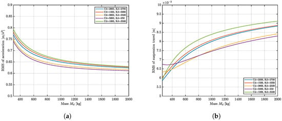
Figure 8.
Influence of the desired inertial mass on suspension performance: (a) RMS of sprung mass acceleration (ride comfort). (b) RMS of suspension deflection (working space).
Increasing the virtual mass effectively suppresses vehicle body vibration by leveraging the inertial filtering effect. Consequently, to attenuate body acceleration under high-intensity excitations, the virtual mass is designed to increase in proportion to the sprung mass acceleration. Conversely, to prevent excessive suspension travel, must be reduced as the suspension deflection increases.
A critical challenge in tuning the control parameters lies in the disparity in magnitude between state variables. Suspension deflection typically fluctuates within the millimeter range, whereas sprung mass acceleration operates in the range of meters per second squared. To mitigate this dimensional discrepancy, a reference offset is introduced to balance the operating ranges of these distinct physical states. This strategy ensures that the tuning gains operate within comparable sensitivity domains. Accordingly, the control law is formulated as:
where is the base mass; and are the tuning gains; and m serves as the threshold offset for deflection.
Finally, regarding the damping properties, Figure 9 illustrates that variations in the impedance damping exert a pronounced influence on both system performance metrics. Specifically, as damping increases, the sprung mass acceleration decreases monotonically, indicating improved vibration suppression. In contrast, the suspension deflection exhibits a non-monotonic trend: it initially decreases to a minimum value before rising again, highlighting the inherent trade-off between vibration isolation and physical travel constraints.
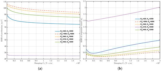
Figure 9.
Influence of the impedance damping on suspension performance: (a) RMS of sprung mass acceleration. (b) RMS of suspension deflection.
As the primary mechanism for energy dissipation, the damping term must be carefully tuned to balance ride comfort with road-holding capability. Building upon the normalization strategy established in the previous section, is designed as a coupled function of both suspension deflection and sprung mass acceleration to address their distinct numerical magnitudes.
The control law is formulated as:
where represents the base damping coefficient; and are the tuning gains for deflection and acceleration, respectively; and the reference threshold is set as m/s2.
In summary, by implementing the variable impedance laws derived above, the controller effectively adapts to road conditions based on real-time state feedback. The system exhibits compliant (soft) characteristics on smooth surfaces to prioritize ride comfort, while transitioning to stiff characteristics on rough terrain to ensure driving safety. This adaptive behavior effectively mitigates the inherent performance trade-off associated with traditional fixed-impedance control.
5. Results of Simulation
To validate the effectiveness of the proposed VIC strategy in off-road environments, a quarter-car active suspension simulation platform was developed in MATLAB/Simulink R2025a. A standard ISO Class-C random road profile was employed as the baseline excitation input. To rigorously capture off-road specificities, the soil parameters identified in the previous section were incorporated into the Bekker model. This integration enables real-time calculation of wheel sinkage and subsequent correction of the effective road excitation.
To quantify the impact of soil sinkage on vehicle dynamics, comparative simulations were performed under two scenarios: a rigid road (no sinkage) and a deformable soft road (with sinkage). The nominal parameters of the quarter-car model used in these simulations are listed in Table 4.
Table 4.
Parameters of the quarter-car model.
5.1. Influence of Soil Sinking on Dynamics
The frequency response characteristics of the sprung mass acceleration, depicted in Figure 10, reveal distinct dynamic differences between the rigid and deformable operating environments. The blue solid line represents the baseline response on a rigid road, exhibiting two characteristic resonant peaks corresponding to the sprung mass resonance (∼1.5 Hz) and the unsprung mass resonance (wheel hop, ∼11 Hz).
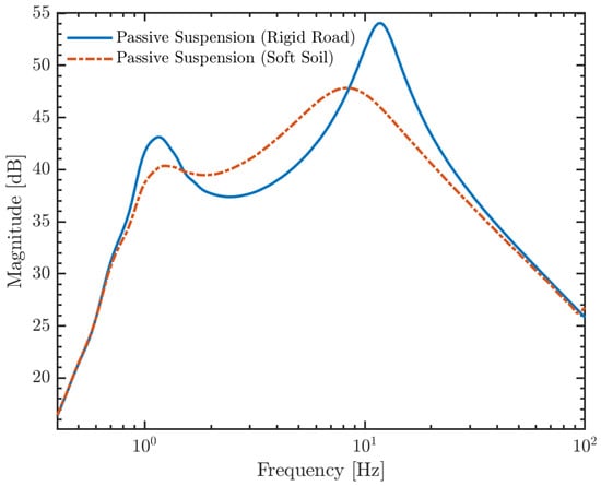
Figure 10.
Frequency response characteristics of sprung mass acceleration: Comparison between rigid road and soft soil interactions.
In contrast, the response under soft soil conditions exhibits distinct dynamic alterations characterized by both amplitude attenuation and spectral shifting. Specifically, the magnitude of the sprung mass acceleration is consistently suppressed across the frequency spectrum, a trend that is particularly pronounced at the second resonant peak where the amplitude drops from approximately 54 dB to 48 dB. This observation corroborates the theoretical assumption that plastic soil deformation dissipates energy, effectively serving as an additional damping mechanism. Concurrently, a noticeable leftward shift towards lower frequencies is observed for both resonant peaks. This frequency migration provides physical evidence for the “series spring” effect inherent in the Bekker model: the soil compliance acts in series with the tire stiffness, thereby reducing the total equivalent stiffness of the system. Governed by the relationship , this reduction in equivalent stiffness leads to a requisite decrease in the vehicle’s natural frequencies. Consequently, the soft terrain functions not only as an energy dissipatorbut also as a low-pass filter, reshaping the system’s spectral characteristics and mitigating the transmission of high-frequency irregularities to the sprung mass.
As illustrated in Figure 11a, the sprung mass acceleration on the soft terrain is generally lower in magnitude compared to that on the rigid road. This reduction is attributed to the plastic sinkage of the soft soil, which dissipates a portion of the impact energy, acting as a natural buffer that provides vibration isolation.
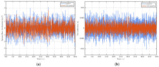
Figure 11.
Comparison of passive suspension dynamics on rigid versus soft terrain. (a) Time-domain response of sprung mass acceleration. (b) Time-domain response of tire deflection.
However, the associated reduction in dynamic tire deflection (shown in Figure 11b) should not be misinterpreted as improved road-holding stability. On the contrary, this phenomenon reflects the insufficient bearing capacity of the terrain. It indicates that the tire is unable to generate adequate ground reaction forces because the soil yields under load, leading to a substantial deterioration in tire–terrain adhesion.
Crucially, this loss of adhesion caused by the compliance of the soft terrain cannot be mitigated by a passive suspension system alone. This limitation underscores the necessity of introducing an active control strategy to optimize the tire’s contact performance while maintaining ride comfort.
5.2. Comparative Assessment of Control Strategies
Building upon the analysis of the limitations of passive suspensions in soft terrain, this section presents a comparative evaluation of the ride comfort performance among three strategies: the Passive Suspension, the Linear Quadratic Regulator (LQR), and the proposed VIC strategy.
In the LQR controller design, the cost function J represents a weighted sum of the sprung mass acceleration (ride comfort), suspension deflection (working space), and tire deflection (road holding):
The specific weighting factors used in this study are , , and . These values were tuned to prioritize the reduction of vertical acceleration while maintaining the suspension workspace and tire deflection within safe limits.
Figure 12a depicts the time-domain response of the sprung mass acceleration. As observed in the plotted traces, the acceleration profile under the VIC strategy exhibits superior vibration suppression, outperforming both the passive and LQR systems. Quantitative analysis (Figure 12b) further reveals that while the LQR controller offers an improvement over the passive system, its effectiveness is marginal, reducing the RMS acceleration by only 9.9%.
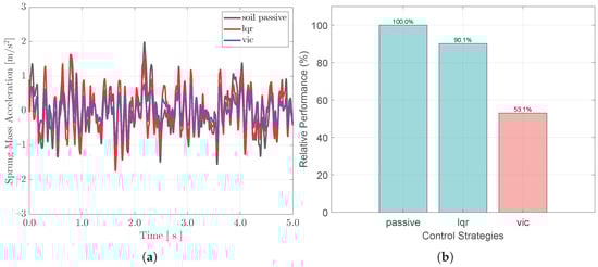
Figure 12.
Assessment of ride comfort performance. (a) Time-domain response of sprung mass acceleration. (b) Comparison of relative RMS acceleration values.
This suboptimal performance is fundamentally attributed to the terrain-induced model mismatch. It is important to clarify that the LQR baseline was intentionally synthesized using the standard nominal quarter-car model assuming a rigid road surface. This setup serves as a ‘state-of-the-practice’ benchmark, reflecting the current industrial reality. Consequently, the comparison highlights the intrinsic limitation of conventional strategies when neglecting soil dynamics. Lacking the feedforward compensation for soil sinkage, the fixed-gain LQR controller lacks the robustness to compensate for the reduced equivalent stiffness and damping variations associated with the soft terrain.
In stark contrast, the proposed VIC strategy—which explicitly accounts for real-time state variations—achieves a substantial 46.9% improvement (lowering the normalized RMS value to 53.1%). This highlights the necessity of adaptive impedance shaping in handling parametric uncertainties within unstructured off-road environments.
While ride comfort optimization is paramount, the control strategy must strictly adhere to physical constraints. Suspension deflection, representing the relative displacement between the wheel and the vehicle body, serves as a critical indicator for assessing the operational safety boundaries of the system.
As illustrated in Figure 13, a distinct characteristic of the VIC strategy is observed: the suspension deflection exhibits wider fluctuations compared to the passive baseline during certain intervals. Quantitatively, the RMS value of the suspension deflection under VIC increases to 111.4% of the passive benchmark.
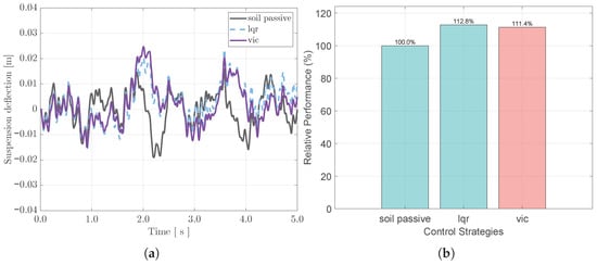
Figure 13.
Assessment of suspension workspace usage. (a) Time history of suspension deflection. (b) Relative suspension deflection intensity normalized to the passive system.
However, this behavior represents a strategic utilization of the suspension stroke rather than a performance deficit. The VIC strategy actively exploits the available suspension travel to dissipate the substantial impact energy arising from the soft terrain, thereby prioritizing the isolation of the sprung mass.
Crucially, despite this increased utilization, the peak suspension deflection for all three control strategies remains strictly confined within the range of mm. This magnitude is significantly below the mechanical bump stops typical of off-road vehicles. Consequently, the system operates entirely within its effective linear range throughout the simulation, avoiding any risk of impact with the stops or structural damage. This confirms that the VIC strategy successfully enhances ride comfort without compromising the structural integrity of the vehicle under complex off-road conditions.
Regarding the wheel–terrain interface, the analysis focuses on tire deflection, a critical metric for off-road operational safety. On loose soil substrates, the shear strength and adhesion coefficient are significantly lower than those on rigid pavements. Consequently, any large amplitude fluctuation in vertical tire load can rapidly lead to a momentary loss of traction, resulting in wheel slip or vehicle entrapment. Therefore, suppressing tire deflection fluctuations to maintain consistent ground contact pressure is a primary objective of the control strategy.
Figure 14 illustrates the time-domain response and the relative RMS comparisons of tire deflection. While the LQR strategy provides marginal improvements in ride comfort, these gains are achieved at the expense of road-holding stability. The RMS value of tire deflection increases to 104.6% of the passive benchmark. This indicates that the LQR controller inherently sacrifices road-holding capability to minimize body acceleration, exacerbating the risk of traction loss in low-adhesion off-road conditions.
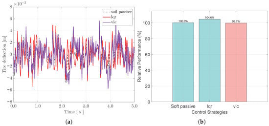
Figure 14.
Analysis of tire deflection characteristics. (a) Time-domain response. (b) Comparison of relative RMS values.
In stark contrast, the proposed VIC strategy demonstrates superior overall performance. Beyond the approximately 50% improvement in ride comfort previously established, it simultaneously reduces the tire deflection RMS value to 99.7% of the passive system. This result confirms that the VIC strategy, through the adaptive modulation of suspension impedance, not only isolates the sprung mass but also successfully suppresses the high-frequency resonance (wheel hop) of the unsprung mass. This ensures that the tires adhere more consistently to the continuously sinking soil surface.
To evaluate the energy efficiency of the proposed active suspension system, the power flow characteristics of the actuator under different control strategies are investigated. It is important to note that the “actuation power” analyzed herein represents the theoretical mechanical power demand () required to execute the control commands within an ideal simulation environment. Consequently, specific hardware constraints, such as actuator bandwidth dynamics and mechanical transmission efficiency, are excluded from this calculation. This approach isolates the intrinsic energy performance of the control algorithms from hardware-specific losses. Figure 15 illustrates the resulting power-velocity distribution profile and the time history of instantaneous power, respectively.
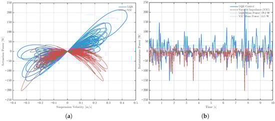
Figure 15.
Actuator power characteristics under different control strategies. (a) Power–velocity distribution profile. (b) Time history of instantaneous power.
The power-velocity plot in Figure 15a provides an intuitive visualization of the actuator’s theoretical dynamic load. The trajectory of the LQR control exhibits a broad, scattered distribution resembling a “butterfly” shape, indicating frequent and high-magnitude energy exchange, particularly during high-velocity suspension movements. This implies a heavy dynamic load on the actuator. In contrast, the power distribution of the VIC is significantly more compact, with the trajectory concentrated near the origin. This phenomenon suggests that by adaptively regulating the virtual impedance parameters, the VIC strategy more effectively leverages the system’s inherent passive dissipation properties to absorb vibration energy, thereby minimizing unnecessary active energy injection.
The time-domain results in Figure 15b further corroborate this advantage. Under the influence of random soft-soil excitations, the instantaneous power of the LQR controller exhibits severe fluctuations with high peak values, resulting in an average power consumption of 28.2 W. In contrast, the proposed strategy demonstrates a much smoother energy consumption profile, effectively suppressing power spikes and substantially reducing the average power consumption to 14.5 W. The VIC strategy achieves an energy saving of approximately 48.6% compared to the LQR baseline. This demonstrates superior energy efficiency alongside its previously established improvements in vehicle ride comfort and road-holding stability.
6. Conclusions
Addressing the deterioration of vertical dynamic performance experienced by off-road vehicles due to the sinkage effect on soft terrain, this study proposes a VIC strategy. Initially, a quarter-car active suspension model incorporating real-time sinkage correction was constructed based on Bekker’s terramechanics theory. By utilizing a Weighted Least Squares (WLS) algorithm to process experimental Bevameter data, the precise identification of key soil parameters was achieved, allowing for the derivation of the nonlinear coupling relationship between road sinkage and tire dynamic load. This modeling approach effectively resolves the prediction distortion inherent to traditional rigid road models and facilitated the elucidation of the “Dual Influence Mechanism” of soft terrain. Simulation analysis reveals that while the plastic deformation of soil exhibits a “low-pass filter” characteristic that partially attenuates vibration, it simultaneously causes a significant reduction in terrain bearing capacity.
To resolve these conflicting objectives, the global optimization capability of the proposed VIC strategy—incorporating variable stiffness, mass, and damping terms—was validated through comparative simulations on an ISO Class-C soft road profile. Results indicate that the VIC strategy significantly outperforms both the LQR and passive suspension benchmarks. Specifically, it achieves a substantial 46.9% reduction in the RMS value of sprung mass acceleration relative to the passive baseline, far exceeding the 9.9% improvement offered by LQR. Crucially, this enhancement in ride comfort is achieved without compromising operational safety; the strategy effectively suppresses high-frequency wheel hop to reduce tire deflection RMS to 99.7% of the passive benchmark—whereas LQR deteriorates this metric to 104.6%—while ensuring suspension travel remains strictly within safe mechanical limits. Furthermore, by leveraging the system’s passive impedance characteristics, the VIC strategy demonstrates superior energy efficiency, operating with an average power consumption of only 14.5 W, which represents a 48.6% energy saving compared to the LQR control.
Despite these promising results, we acknowledge two primary limitations in the current study. First, the quarter-car framework simplifies vehicle–terrain interaction by neglecting the multi-pass effect. In real-world off-road scenarios, the soil’s response to repetitive loading significantly alters the terrain properties encountered by the rear axle due to prior compaction. Second, the reported energy efficiency is based on ideal actuator dynamics. In practical applications, hardware constraints such as actuator bandwidth lag and power saturation—which were not modeled here—may attenuate the actual energy-saving effects.
Consequently, future work will focus on two directions: (1) extending the framework to full-vehicle configurations to explicitly model soil compaction and establish a quantitative mapping between load cycles and parameter evolution; and (2) conducting Hardware-in-the-Loop (HiL) experiments to validate the VIC strategy under realistic actuator bandwidth and power constraints.
In summary, the methodology proposed in this paper effectively resolves the multi-objective conflicts between comfort, safety, and energy consumption, providing a significant theoretical foundation for the design of high-performance all-terrain vehicle chassis systems.
Author Contributions
Conceptualization, J.Z. and Y.Z.; methodology, J.Z.; software, J.Z. and M.L.; validation, M.L.; investigation, J.Z.; resources, Y.Z.; data curation, M.L.; writing—original draft preparation, J.Z. and M.L.; writing—review and editing, Y.Z., Y.D. and X.J.; visualization, M.L.; supervision, Y.Z.; project administration, Y.Z.; funding acquisition, Y.Z. All authors have read and agreed to the published version of the manuscript.
Funding
This research was funded by the Major Program of National Natural Science Foundation of China, grant number 52394261 and the Science and Technology Development Project of Jilin Province, grant number 202502007.
Data Availability Statement
The raw data supporting the conclusions of this article will be made available by the authors on request.
Conflicts of Interest
Xulong Jin is an employee of China First Automobile Group Co., Ltd. Youlong Du is an employee of Faw-Tokico Shockabsorber Co., Ltd. The paper reflects the views of the scientists and not the company.
References
- Hua, C.; Zhang, W.; Fu, H.; Zhang, Y.; Yu, B.; Jiang, C.; Wei, Y.; Chen, Z.; Kuang, X. The Prediction Method and Application of Off-Road Mobility for Ground Vehicles: A Review. World Electr. Veh. J. 2025, 16, 47. [Google Scholar] [CrossRef]
- Zhou, S.; Liu, Z.; Gao, H.; Zhao, M.; Wang, L.; Jiang, G. Turn-on/off control with dynamic significance of active suspension based on energy dissipation principle for manned lunar rover under low gravity and rough terrain conditions. Mech. Syst. Signal Process. 2024, 209, 111071. [Google Scholar] [CrossRef]
- Bryant, A.; Beno, J.; Weeks, D. Benefits of Electronically Controlled Active Electromechanical Suspension Systems (EMS) for Mast Mounted Sensor Packages on Large Off-Road Vehicles; SAE Technical Paper; SAE International: Warrendale, PA, USA, 2011. [Google Scholar]
- Barbieri, N. The optimal performance index for an off–road vehicle with passive and active suspension systems. Int. J. Heavy Veh. Syst. 1995, 2, 225–237. [Google Scholar]
- Sharp, R.; Hassan, S. The relative performance capabilities of passive, active and semi-active car suspension systems. Proc. Inst. Mech. Eng. Part D Transp. Eng. 1986, 200, 219–228. [Google Scholar] [CrossRef]
- Ben, L.Z.; Hasbullah, F.; Faris, F.W. A comparative ride performance of passive, semi-active and active suspension systems for off-road vehicles using half car model. Int. J. Heavy Veh. Syst. 2014, 21, 26–41. [Google Scholar] [CrossRef]
- Li, M.; Xu, J.; Wang, Z.; Liu, S. Optimization of the semi-active-suspension control of BP neural network PID based on the sparrow search algorithm. Sensors 2024, 24, 1757. [Google Scholar] [CrossRef]
- Zhang, S.; Li, M.; Li, J.; Xu, J.; Wang, Z.; Liu, S. Research on ride comfort control of air suspension based on genetic algorithm optimized fuzzy PID. Appl. Sci. 2024, 14, 7787. [Google Scholar] [CrossRef]
- Pan, J.; Li, W.; Zhang, H. Control algorithms of magnetic suspension systems based on the improved double exponential reaching law of sliding mode control. Int. J. Control. Autom. Syst. 2018, 16, 2878–2887. [Google Scholar] [CrossRef]
- Ma, M.; Chen, H.; Liu, X. Robust H-infinity control for constrained uncertain systems and its application to active suspension. J. Control Theory Appl. 2012, 10, 470–476. [Google Scholar] [CrossRef]
- Wang, C.; Cui, X.; Zhao, S.; Zhou, X.; Song, Y.; Wang, Y.; Guo, K. A deep reinforcement learning-based active suspension control algorithm considering deterministic experience tracing for autonomous vehicle. Appl. Soft Comput. 2024, 153, 111259. [Google Scholar] [CrossRef]
- Taheri, S.; Sandu, C.; Taheri, S.; Pinto, E.; Gorsich, D. A technical survey on Terramechanics models for tire-terrain interaction used in modeling and simulation of wheeled vehicles. J. Terramechanics 2015, 57, 1–22. [Google Scholar] [CrossRef]
- He, R.; Sandu, C.; Khan, A.K.; Guthrie, A.G.; Els, P.S.; Hamersma, H.A. Review of terramechanics models and their applicability to real-time applications. J. Terramechanics 2019, 81, 3–22. [Google Scholar] [CrossRef]
- Ishigami, G.; Miwa, A.; Nagatani, K.; Yoshida, K. Terramechanics-based model for steering maneuver of planetary exploration rovers on loose soil. J. Field Robot. 2007, 24, 233–250. [Google Scholar] [CrossRef]
- Buzhardt, J.; Tallapragada, P. A Koopman operator approach for the vertical stabilization of an off-road vehicle. IFAC-PapersOnLine 2022, 55, 675–680. [Google Scholar] [CrossRef]
- Lyu, S.; Zhang, W.; Yao, C.; Zhu, Z.; Jia, Z. Modeling and analysis of a reconfigurable rover for improved traversing over soft sloped terrains. Biomimetics 2023, 8, 131. [Google Scholar] [CrossRef] [PubMed]
- Lv, S.; Zhao, Y.; Chen, Z.; Gao, C.; Hu, L.; Jia, Z. Improved rover mobility over loose deformable slopes through active control of body-rotating mechanism. In Proceedings of the 2021 27th International Conference on Mechatronics and Machine Vision in Practice (M2VIP), Shanghai, China, 26–28 November 2021; IEEE: Piscataway, NJ, USA, 2021; pp. 606–611. [Google Scholar]
- Lu, S.; Xu, X.; Wang, W. Coupling dynamic model of vehicle-wheel-ground for all-terrain distributed driving unmanned ground vehicle. Simul. Model. Pract. Theory 2023, 128, 102817. [Google Scholar] [CrossRef]
- Surkutwar, Y.; Vilsan, A.; Sandu, C.; Untaroiu, C. Comparative analysis of FEM tire-soft snow interaction and theoretical model based on Bekker’s coefficients. IOP Conf. Ser. Mater. Sci. Eng. 2024, 1303, 012046. [Google Scholar] [CrossRef]
- Edwards, M.B.; Dewoolkar, M.M.; Huston, D.R.; Creager, C. Bevameter testing on simulant Fillite for planetary rover mobility applications. J. Terramechanics 2017, 70, 13–26. [Google Scholar] [CrossRef]
- Levasseur, S.; Malécot, Y.; Boulon, M.; Flavigny, E. Soil parameter identification using a genetic algorithm. Int. J. Numer. Anal. Methods Geomech. 2008, 32, 189–213. [Google Scholar] [CrossRef]
- Hutangkabodee, S.; Zweiri, Y.H.; Seneviratne, L.D.; Althoefer, K. Soil parameter identification for wheel-terrain interaction dynamics and traversability prediction. Int. J. Autom. Comput. 2006, 3, 244–251. [Google Scholar] [CrossRef]
- Wong, J. Data processing methodology in the characterization of the mechanical properties of terrain. J. Terramechanics 1980, 17, 13–41. [Google Scholar] [CrossRef]
- Hutangkabodee, S.; Zweiri, Y.H.; Seneviratne, L.D.; Althoefer, K. Model-based soil parameter identification for wheel-terrain interaction dynamics. IFAC Proc. Vol. 2007, 40, 578–583. [Google Scholar] [CrossRef]
- Tao, G. Adaptive output tracking control with reference model system uncertainties. Automatica 2025, 174, 112174. [Google Scholar] [CrossRef]
- Hogan, N. Impedance control: An approach to manipulation. In Proceedings of the 1984 American Control Conference, San Diego, CA, USA, 6–8 June 1984; IEEE: Piscataway, NJ, USA, 1984; pp. 304–313. [Google Scholar]
- Hogan, N. Impedance control: An approach to manipulation: Part II—Implementation. J. Dyn. Syst. Meas. Control 1985, 107, 8–16. [Google Scholar] [CrossRef]
- Kong, L.; He, W.; Yang, C.; Li, Z.; Sun, C. Adaptive fuzzy control for coordinated multiple robots with constraint using impedance learning. IEEE Trans. Cybern. 2019, 49, 3052–3063. [Google Scholar] [CrossRef] [PubMed]
- Duan, J.; Gan, Y.; Chen, M.; Dai, X. Adaptive variable impedance control for dynamic contact force tracking in uncertain environment. Robot. Auton. Syst. 2018, 102, 54–65. [Google Scholar] [CrossRef]
- Blaya, J.A.; Herr, H. Adaptive control of a variable-impedance ankle-foot orthosis to assist drop-foot gait. IEEE Trans. Neural Syst. Rehabil. Eng. 2004, 12, 24–31. [Google Scholar] [CrossRef]
- Zhang, Y.; Li, T.; Tao, H.; Liu, F.; Hu, B.; Wu, M.; Yu, H. Research on adaptive impedance control technology of upper limb rehabilitation robot based on impedance parameter prediction. Front. Bioeng. Biotechnol. 2024, 11, 1332689. [Google Scholar] [CrossRef]
- Kim, J.; Guerrero, J.M.; Rodriguez, P.; Teodorescu, R.; Nam, K. Mode adaptive droop control with virtual output impedances for an inverter-based flexible AC microgrid. IEEE Trans. Power Electron. 2010, 26, 689–701. [Google Scholar] [CrossRef]
- Cespedes, M.; Sun, J. Adaptive control of grid-connected inverters based on online grid impedance measurements. IEEE Trans. Sustain. Energy 2014, 5, 516–523. [Google Scholar] [CrossRef]
- Dehghan, M.; Fateh, M.M.; Ghalehnoie, M. A fuzzy-supervised impedance control for an active suspension system. J. Vib. Eng. Technol. 2023, 11, 3257–3266. [Google Scholar] [CrossRef]
- Fateh, M.M.; Zirkohi, M.M. Adaptive impedance control of a hydraulic suspension system using particle swarm optimisation. Veh. Syst. Dyn. 2011, 49, 1951–1965. [Google Scholar] [CrossRef]
- Kang, S.; Kong, L.; Han, C.; Qiang, H.; Liu, K. Study on the impedance of active suspension drive unit under transverse slope condition based on track sensitivity. J. Braz. Soc. Mech. Sci. Eng. 2024, 46, 239. [Google Scholar] [CrossRef]
- Habibi, H. Control of Active Suspension Systems Based on Mechanical Wave Concepts. Actuators 2025, 14, 230. [Google Scholar] [CrossRef]
- ISO 8608:2016; Mechanical Vibration—Road Surface Profiles—Reporting of Measured Data. ISO: Geneva, Switzerland, 2016.
- GB/T 7031-2005; Mechanical Vibration—Road Surface Profiles—Reporting of Measured Data. Standards Press of China: Beijing, China, 2005.
Disclaimer/Publisher’s Note: The statements, opinions and data contained in all publications are solely those of the individual author(s) and contributor(s) and not of MDPI and/or the editor(s). MDPI and/or the editor(s) disclaim responsibility for any injury to people or property resulting from any ideas, methods, instructions or products referred to in the content. |
© 2026 by the authors. Licensee MDPI, Basel, Switzerland. This article is an open access article distributed under the terms and conditions of the Creative Commons Attribution (CC BY) license.