Abstract
Wire-rope isolators (WRIs) are widely used in vibration and seismic protection due to their multidirectional flexibility and amplitude-dependent hysteretic damping. However, their complex nonlinear behavior, especially under inclined and combined-mode loading, poses challenges for predictive modeling. This study presents a simplified finite-element modeling framework using constant-property Timoshenko beam elements with tuned Rayleigh damping to simulate WRI behavior across various configurations. Benchmark validation against analytical ring deformation confirmed the model’s ability to capture geometric nonlinearities. The framework was extended to five WRI types, with effective cross-sectional properties calibrated against vendor-supplied quasi-static data. Dynamic simulations under sinusoidal excitation demonstrated strong agreement with experimental force-displacement loops in pure modes and showed moderate accuracy (within 29%) in inclined configurations. System-level validation using a rocking-control platform with four inclined WRIs showed that the model reliably predicts global stiffness and energy dissipation under base accelerations. While the model does not capture localized nonlinearities such as pinched hysteresis due to interstrand friction, it offers a computationally efficient tool for engineering design. The proposed method enables rapid evaluation of WRI performance in complex scenarios, supporting broader integration into performance-based seismic mitigation strategies.
1. Introduction
Wire-rope isolators (WRIs) are versatile helical spring–damper devices made of steel cable bundles attached between rigid brackets. Their unique geometry provides them with multidirectional flexibility and significant hysteretic damping through interwire friction. These attributes have made WRIs popular for protecting sensitive equipment from shock and vibration in industries ranging from military and aerospace to infrastructure and seismic engineering. WRIs exhibit strongly nonlinear behavior. Under deflection, the ring-shaped geometry of the isolator deforms and uncoils, causing its effective stiffness to harden or soften, while friction between the strands dissipates energy. Early research demonstrated that the damping in the helical wire-rope isolator is governed by sliding friction among the cable wires [1].
Early experimental studies established that WRI responses are highly nonlinear and hysteretic due to their geometry and internal friction. Tinker and Cutchins [1] observed pronounced hysteresis loops in WRI force–displacement cycles, attributing the dissipation to Coulomb friction as wires slide against each other. Later works quantified these effects. For example, Salvatore et al. [2] conducted dynamic tests on vertical WRIs and noted asymmetric restoring forces; the isolator softens in compression but stiffens in tension as the cables straighten. This tension–compression asymmetry grows with larger vibration amplitudes, whereas shear and roll modes tend to produce more symmetric loops. Notably, the energy dissipation in WRIs is largely amplitude-dependent and frequency-independent. The loop shape remains similar across loading rates, which is a desirable property for broadband vibration isolation. Comprehensive cyclic tests by Leblouba et al. [3] confirm rate-independent behavior of WRI hysteresis loops. This study highlights the influence of WRI geometry on its multi-directional behavior; the effective damping of an isolator is affected by the height-to-width ratio and the displacement amplitude. Overall, the experimental literature presents a consistent picture of WRIs as rate-independent, nonlinear spring–dampers whose properties evolve with amplitude and accumulated travel but remain stable across frequency. Any reliable WRI model must therefore incorporate geometric nonlinearity and amplitude-dependent hysteresis.
Purely analytical modeling of WRIs has generally been confined to idealized or single-strand cases, since closed-form mechanics struggle to capture the full helical geometry and interstrand contact. The most widely used model to capture the WRIs’ behavior is the Bouc–Wen model [4], originally formulated by Wen for smooth hysteretic systems. Demetriades et al. [5] were among the first to adopt a Bouc–Wen formulation to simulate WRI loops in seismic analyses, treating the isolator as an equivalent nonlinear spring with parameters calibrated from experiments. Ni et al. [6] later performed cyclic loading tests to identify Bouc–Wen parameters for WRIs. Recent efforts have extended the classical Bouc–Wen model to capture the asymmetric, preload-dependent hysteresis loops observed in frictional isolators. For example, Maleki et al. [7] introduced a modified Bouc–Wen formulation in which the stiffness parameter varies exponentially with the instantaneous normal force. These Bouc–Wen-type models efficiently fit loops in individual directions, but usually require direction-specific calibration and careful tuning to reproduce pinching, mixed hardening/softening, or combined-mode effects.
Complementing phenomenological hysteresis, rate-independent, macro-models for WRIs along principal transverse directions (roll and shear) have been proposed by Vaiana et al. [8]. Their algebraic formulation employs five parameters of clear mechanical meaning and captures kinematic hardening efficiently, with validation in conventional modes; however, recalibration is needed when axial force (or inclination) changes, indicating sensitivity to loading conditions.
Mechanical beam-based models in the literature aim to enhance physical interpretability by representing ropes as hierarchical, helically wound structures with frictional interfaces. Foti et al. [9] proposed a mechanical modeling approach that treats the wire rope as a beam-like element composed of helically wound strands and wires, capturing its internal hierarchy and frictional interactions. Central to this approach is a nonlinear moment-curvature law that accounts for the transition between full-stick and full-slip states of interwire contact, which governs the hysteretic bending response. This constitutive behavior is embedded within a corotational beam finite-element (FE) framework. However, the formulation assumes that the curvature threshold for sliding is constant and unaffected by axial force. This simplification limits the model’s accuracy, particularly under compressive loading. As a result, the model may underestimate energy dissipation and misrepresent tangent stiffness in compression scenarios. Despite this limitation, the mechanical model represents a promising foundation for the mechanical modeling of WRIs. Bonisoli et al. [10] investigated the nonlinear dynamic behavior of cantilever beams with magnetic interactions and non-holonomic contact, using laser profilometry and time–frequency analysis. Their approach interprets the nonlinear responses through multiple linearized Euler–Bernoulli configurations and model-order reduction, demonstrating that a sequence of linearized models can effectively capture the global dynamics while revealing nonlinear fingerprints such as superharmonics and time-varying frequencies. These findings support the use of linear elastic beam representations at the macroscopic scale, while acknowledging localized nonlinear mechanisms at interfaces, and reinforce the value of simplified modeling strategies for complex systems.
Although full 3D contact FE simulations of wire-rope isolators (WRIs), in which every strand and frictional interface is explicitly meshed, may reproduce both elastic stiffness and static hysteresis, their computational demands and contact-model calibration requirements make them impractical for routine design or for rapid exploration of inclined/combined configurations. FE models for simple straight wire-rope strands were developed by Jiang et al. [11] and Nawrocki and Labrosse [12]. Elata et al. [13] defined a modeling framework based on explicit parametrization of each wire’s double-helix trajectory around an independent wire-rope core, where the helix angle and phase of every wire are defined by simple trigonometric functions of its axial and circumferential positions. More recently, Gai et al. [14] demonstrated that a carefully parameterized full-pitch 3D FE model using reduced-integration hexahedral elements can predict both intact and broken-wire behavior with high fidelity. Together, modern FE approaches, when coupled with precise geometric parameterization, can reproduce small-strain stiffness and large-deformation hysteresis of WRIs with high fidelity, substantially reducing reliance on exhaustive laboratory testing, albeit at the cost of increased computational effort.
The combined nonlinear stiffness and rate-independent damping allow WRIs to perform over broad frequency ranges and large displacements without performance degradation. However, these same nonlinearities pose challenges for design. Performance-based design of WRI systems demands nonlinear analyses that quantify isolator deformations under diverse excitations, orientations, and loading scenarios. WRI properties depend on the load direction, amplitude, and cable geometry, and manufacturers usually provide only standard quasi-static curves (e.g., vertical compression, horizontal shear) for a few configurations. Practitioners lack detailed force–displacement relationships under dynamic and non-standard loading; for instance, WRIs are inclined to resist the rocking of equipment. As a result, the integration of WRIs into performance-based designs for rocking control can be limited, since predictive models for arbitrary orientations or different dynamic excitations have not been readily available.
Applications underscore the need for improved WRI modeling. Marin-Artieda and Han [15], for example, investigated WRI “energy dissipation platforms” to control the overturning of equipment under earthquake excitations. Accurate prediction of WRI performance in energy-dissipation platforms demands characterization under combined-mode and inclined conditions, which add more challenges for predictive modeling and design integration. Unfortunately, solutions for the full multistrand helical geometry, together with interstrand contact, under combined working modes do not exist. Traditional modeling approaches, such as the Bouc–Wen formulation, have been employed to simulate WRI behavior, but they often require extensive parameter tuning and struggle to capture the full range of nonlinearities. While high-fidelity FE simulations that explicitly model each cable strand and its frictional interfaces may reproduce this complex dynamic behavior, their steep computational cost and the need for expert contact-model calibration severely limit their use in practical design workflows.
These observations motivate the development of compact models that preserve geometric realism, accurately predict global stiffness and energy across orientations, and require minimal calibration making them cost-effective tools for use in engineering practice. In this spirit, the present study proposes a simplified yet robust FE modeling framework experimentally validated. The FE modeling framework efficiently captures the nonlinear stiffness and damping of WRIs in various loading modes, including tension-compression, shear, roll, and inclined configurations. The model leverages Timoshenko beam elements to represent the cable helix with constant-effective bending, shear, and axial sectional properties, incorporates Rayleigh-type damping calibrated to mimic frictional energy dissipation, and implements large displacements and rotations. This approach dramatically reduces model complexity while preserving the key geometric nonlinearities of the isolator. The accuracy of the proposed model is demonstrated by comparison to dynamic tests, and its utility is illustrated in predicting the response of WRI-based isolation systems that would be difficult to test experimentally. This approach captures the essential geometric nonlinearities and energy dissipation mechanisms of WRIs while maintaining computational efficiency. The model is validated against a benchmark analytical solution and experimental data across multiple WRI types and loading configurations. This work contributes new knowledge by demonstrating that a reduced-complexity beam-based model can reliably simulate global stiffness and damping behavior of WRIs under both component-level and system-level conditions. It enables efficient evaluation of WRI performance in non-standard configurations, such as rocking-control platforms, and supports broader integration of WRIs into performance-based seismic and vibration mitigation designs.
2. Definition of the WRI FE Model
Figure 1 presents two photographs of a typical WRI used in this study, indicating the conventional working modes shear and roll in the horizontal direction and tension-compression in the vertical direction, together with the analogy of its cross-section to an elliptical ring.
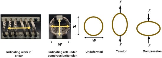
Figure 1.
Photographs of a typical WRI showing shear, roll, and tension-compression modes (arrows indicating working mode), with the analogy of the WRI as an elliptical ring.
2.1. Identifying Basic Elements of the FE Models of WRIs
The variation of overall stiffness in WRIs arises primarily from their helical geometry. As the isolator deforms under tension or compression, its effective height H changes, altering the global area moments of inertia. Modeling the WRI cross-section as an elliptical ring (Figure 1) with major radius W and minor radius H, the principal moments of inertia are given by the following:
Subsequently, the strain energy at any instant is modified for the corresponding height of the helical ring at a specific deformation level.
In this study, the FE model (FEM) for WRIs is developed using Timoshenko beam theory, which extends the classical Euler–Bernoulli beam theory by incorporating transverse shear deformation. Unlike Euler–Bernoulli theory, which assumes that plane sections remain perpendicular to the neutral axis, the Timoshenko theory allows these sections to rotate independently [16]. Timoshenko beam elements are particularly advantageous in modeling complex geometries and short-span structures, as they can capture higher-order cross-sectional deformation modes. Furthermore, the beam element selected for constructing the FE models should allow the analysis of large rotations and displacements.
To evaluate the capability of Timoshenko beam elements in capturing ring-type geometric nonlinearity, this study employs the Abaqus (version 2016) B31 element with nonlinear geometry enabled (*NLGEOM) and a linear elastic material model [17]. As a benchmark, the analytical work of Breslavsky et al. [18] is utilized, which provides solutions for both linearly elastic and large-strain Neo–Hookean circular rings, which serve as a reference for verifying FE implementations across both small- and large-deformation regimes. To replicate the benchmark scenario, a quarter-ring segment is modeled under uniform radial pressure, with symmetric boundary conditions applied to reflect the full ring behavior (Figure 2a). This configuration enables direct comparison between the FEM results and the analytical solutions, thereby validating the geometric nonlinearity captured by the B31 formulation. Using only ten B31 elements, a mesh-sensitivity study confirmed convergence. Figure 2b compares the FE-generated pressure-normalized deformation curve (, w radial displacement normalized by its thickness h) to the axisymmetric analytical solutions of [18].
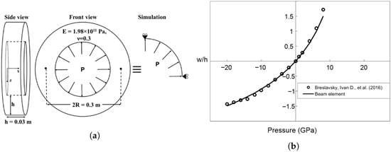
Figure 2.
Timoshenko beam FE model against solutions for circular rings under pressure [18]. (a) Ring geometry. (b) FE beam-model (Timoshenko B31 elements) against the benchmark solution [18].
Figure 2b shows strong agreement throughout the pressure (P) spectrum between the normalized radial deflection from Breslavsky et al. [18] and the Timoshenko-beam FEM approximation. Under the considered pressures, the FEM results lie within only a few percent of the analytical benchmark, confirming that even a coarse mesh of Timoshenko beam elements reproduces the ring’s nonlinear stiffness and large-strain response. In the small-strain regime ( GPa), the behavior is nearly linear. Beyond this threshold, the tensile branch () exhibits rapid hardening, whereas the compressive branch () softens more gradually, yielding an inherent asymmetry in . Without any additional calibration, the beam-element model captures both features solely from the ring’s geometry and material properties. At the highest pressures examined (around 8 GPa), the FEM solution underestimates the normalized deflection by about 12%. However, the FEM results remains close to the analytical curve, and the observed deviation is largely attributed to the steepness of the curve in that region, which amplifies small differences in deflection. This benchmark thus confirms that a Timoshenko-beam approximation with nonlinear geometry analysis can reliably capture large-strain ring deformations, giving confidence that the same methodology will extend effectively to the more complex helical geometry of WRIs.
2.2. Effective Cross-Section Definition and Damping Parameters
The cross-section of a rope consisting of twisted wires and strands is simplified to a generalized section with a constant effective area and an effective area moment of inertia, neglecting friction between individual wires. These effective properties are estimated and tuned using vendor-supplied force-deformation data for quasi-static tests under conventional working modes. Figure 3 depicts this process, and the geometry of a WRI and its typical cross section consisting of multiple twisted strands around a core are shown schematically. The rope is modeled as a beam element of effective diameter , whose cross-sectional properties derive from n symmetrically intertwined strands (see Figure 3). Consequently, the effective area becomes the sum of individual strand areas, and the effective inertia about the centroid is the sum of each strand’s inertia plus parallel-axis contributions. For a rope with n strands, the generalized section carries the combined properties of all strands.
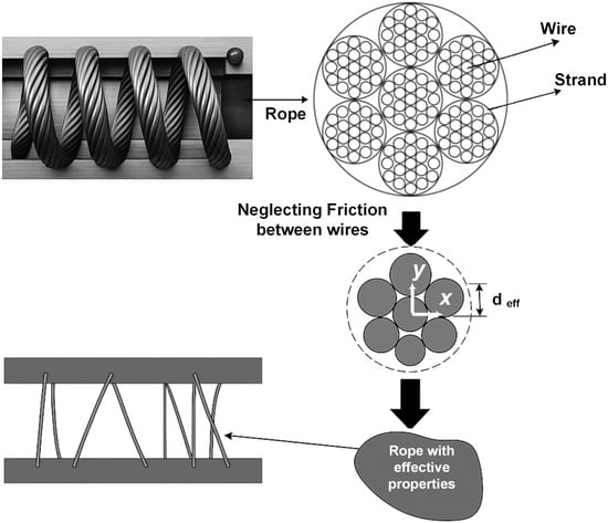
Figure 3.
Effective cross-section properties of WRIs.
A rope’s multi-wire cross-section, consisting of n twisted strands, is represented by a single circular section of effective diameter . This equivalent section is calibrated to match vendor-supplied quasi-static load-displacement data. Neglecting interwire friction, each strand’s contribution is defined by the following:
where and are the strand area and area moment of inertia. Summing over the n strands located at coordinates relative to the section centroid yields the generalized section properties:
where the effective area and area moment of inertia values—, , and —are then assigned to the beam elements to represent the rope under static and dynamic loads.
The effective properties in Equations (3)–() assume a constant cross-section and linear elasticity at the wire-bundle level.
As is well documented in the literature and confirmed through experimental studies, WRIs exhibit damping that varies significantly with displacement amplitude, reflecting their nonlinear and hysteretic nature [19]. This behavior arises primarily from two mechanisms: Coulomb friction, when individual strands slide against one another, and viscous stick-slip effects, in which strands temporarily adhere before slipping [1]. Both mechanisms evolve with deformation, causing the effective stiffness to change with increasing displacement and making direct strand-level modeling computationally demanding and difficult to calibrate. To enable practical implementation while still capturing the essential energy dissipation, the combined damping behavior is approximated using Rayleigh damping. Rayleigh damping inherently neglects the amplitude-dependent and hysteretic characteristics of WRIs. Nonetheless, it remains a convenient classical formulation for simplified approaches, and is employed here to estimate the equivalent energy dissipation effects of WRIs.
where C is the damping matrix, M and K are the mass and stiffness matrices, and and are the mass- and stiffness-proportional damping coefficients, respectively.
In the search for the most appropriate Rayleigh damping parameters ( and ), it is important to recognize that, when applied in systems undergoing stiffness softening, such as WRIs, this formulation can introduce artificial effects. In particular, the stiffness-proportional term may generate damping forces that are unrealistically large relative to the restoring forces, resulting in excessive damping and, in some cases, unconservative predictions [20,21]. Likewise, in base-isolated systems or in cases dominated by rigid-body motions, the mass-proportional damping component can suppress low-frequency response and distort system dynamics, resulting in unrealistic damping forces [20].
To address these issues, preliminary calibration trials were conducted using experimental force–displacement data. Based on these evaluations, a Rayleigh damping model with and tuned was adopted to reproduce the observed energy dissipation in sinusoidal load–deflection tests. This approach is consistent with recommendations in the literature, which recommend eliminating the mass-proportional term in base-isolated systems to avoid unrealistic low-frequency damping [21,22]. While this assumption is appropriate for the conditions considered here, the selection of and should be system-specific.
Table 1 lists the five helical isolator types used in this study, including their designations and key geometric dimensions. Figure 4 illustrates the typical WRI geometry, with dimension labels corresponding to those introduced in Table 1.

Table 1.
Geometric dimensions of WRI types.
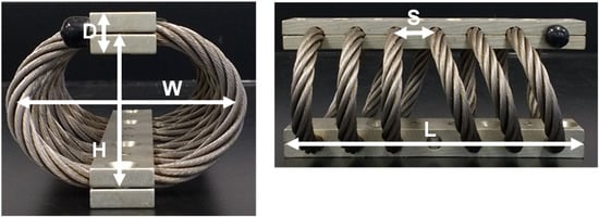
Figure 4.
Dimensions of WRI used in the study.
Using the basic geometry illustrated in Figure 4, the WRI’s helical centerlines as line sketches can be defined in any CAD software (2019). Exporting these sketches as standard geometry files allows direct import into an FE environment, where the centerlines can be used to generate the mesh of beam elements that represent the isolator’s helical shape.
The next step in the modeling workflow is to determine the constant WRI’s effective cross-sectional properties to assign to the beam elements of the FEM. The effective cross-sectional area and moments of inertia are calculated using Equations (3)–(). The simplification of constant sectional properties is consistent with the global-response objectives of the study, namely capturing multimode stiffness and energy trends with minimal calibration effort.
Calibration of the effective properties is performed against static force–displacement curves obtained from vendor catalogs for each WRI type in its standard working modes, pure shear, pure roll, vertical tension-compression, and a inclined orientation. The effective area and moments of inertia are tuned so that the FE predictions reproduce the cataloged curves, ensuring that the simplified beam representation accurately captures the quasi-static stiffness of the isolator. For the WRIs considered in this study, only minor tuning was required to obtain reasonable agreement across all working modes. Nevertheless, it is difficult to identify a single set of constant section properties that achieves equally high accuracy under all loading conditions. In line with the intended use of this FEM framework for engineering design practice, one representative set of effective properties is consistently maintained throughout the analyses.
Figure 5 illustrates the calibration procedure for WRI Type 3. A single set of effective cross-sectional properties is defined that closely reproduces the quasi-static stiffness in all conventional modes. A comparison of experimental (vendor data) and FEM force–displacement curves shows that:
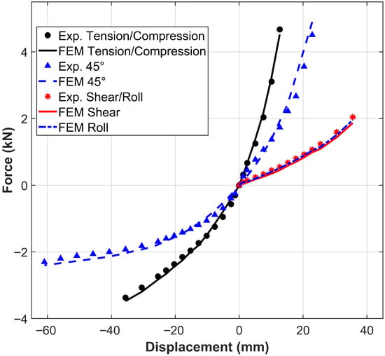
Figure 5.
Static analysis of WRI Types 3 for tuning effective properties.
- In pure tension–compression, the FEM reproduces the experimental stiffness within 5%.
- In pure shear and roll, the FEM and experimental curves are nearly identical across the entire displacement range.
- In the inclined mode, which combines tension–compression and roll (or shear), the FEM matches the experimental curves up to about mm, but underestimates tensile stiffness by about 10% and compressive stiffness by about 5%. At larger displacements (around mm), the experimental tangent slope exceeds the FEM prediction by roughly 15–20%.
These discrepancies between FEM and vendor curves for the inclined mode reflect the difficulty of representing coupled geometric nonlinearity and interstrand friction with a single, constant-property cross-section. Nonetheless, even in combined-mode () loading at large displacements, the FEM peak predictions remain within 20% of the experimental stiffness values, and the FEM result remains close to the experimental curves.
3. Responses of Individual WRIs Under Sinusoidal Excitations
3.1. Description of the WRI Settings and Assessment Parameters
The FEM in this study was developed based on the available experimental data, which provided force–displacement relationships necessary for evaluating model performance. However, the experimental setup was constrained by the load capacity of the equipment and the design of the fixtures used to secure WRIs. Experimental testing was conducted at the Applied Mechanics and Materials Research Laboratory at Howard University, using an axial-torsion system to measure the forces exerted on the specimens and generate force-displacement loops. To accommodate different loading configurations, including inclined angle loading, custom steel fixtures were designed to mount the WRIs securely on the test rig. Test protocols were defined to characterize the WRIs under each configuration, taking into account both the isolators’ mechanical properties and the limitations of the testing apparatus and fixtures.
The FEM of the five types of WRIs in conventional working modes and with different angles of inclination (0°, 30°, 45°, and 60°) were subjected to sinusoidal displacement series. The displacement histories are applied to the top bar of the WRIs, while the bottom bar is fixed in all six degrees of freedom to mimic the experimental conditions. All applied displacements can be described by a sinusoidal function with a constant amplitude of 3, 6, 10, and 20 mm and with periods varying between 1, 10, and 100 s. The force–deformation relationships of the WRIs are analyzed to identify the stiffness and damping of the individual isolators. The effective stiffness and damping of the systems were calculated using the expressions below:
where is the overall effective stiffness, and are the maximum tensile and compressive forces, respectively, and are the maximum tensile and compressive displacements, respectively, is the tensile effective stiffness, is the compressive effective stiffness, is the effective damping, and is the total area of the hysteresis loop.
The numerical predictions were compared with available experimental responses. Figure 6 presents photographs of the experimental setup at the top and the corresponding numerical models of the WRIs at the bottom.
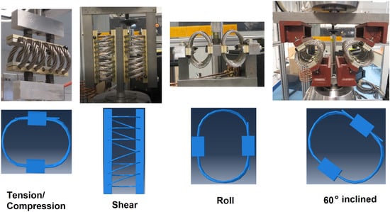
Figure 6.
(Top): Photograph of the experimental setup. (Bottom): Corresponding FEM of the WRIs.
3.2. Results of Individual WRIs Under Sinusoidal Excitations Under Tension-Compression
This subsection illustrates the FE model’s performance for WRI Type 3 under pure tension–compression sinusoidal loading (10 s period, 6 mm and 10 mm amplitudes), as plotted in Figure 7. At 6 mm amplitude, the FEM underestimates the experimental effective stiffness by 5% and underpredicts damping by approximately 6%. The compressive branch is captured almost exactly, while tensile stiffness is underestimated by about 10%. Increasing the amplitude to 10 mm yields identical effective stiffness in both experiment and FEM, with the damping ratio differing by 4%. In this case, the FEM slightly over-predicts tensile stiffness by 4% and compressive stiffness by 7%. Qualitatively, the FE hysteresis loops closely match the experimental curves in both slope and overall shape, though the model exhibits minor deviations at the tension peak for 6 mm and at the compression peak for 10 mm. These results confirm that, although the FEM reproduces overall stiffness at larger amplitudes, it still tends to smooth out the subtle asymmetries and energy dissipation mechanisms observed in the physical isolator.
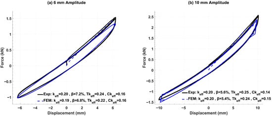
Figure 7.
Force–displacement curves for WRI Type 3 under pure tension–compression sinusoidal loading (10 s period).
FEM of WRIs rotated by , , and were developed to capture the combined tension–compression–roll response introduced by inclination (see the left side of Figure 6). Representative force–displacement loops for rotations of and on WRI Types 3 and 4 are shown in Figure 8 and Figure 9, respectively.
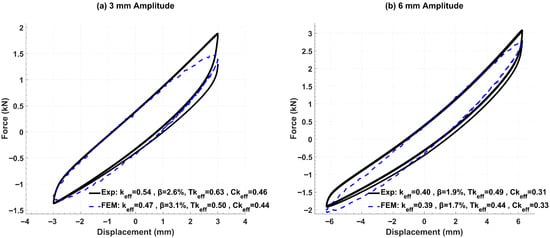
Figure 8.
FEM vs. experimental force–displacement loops for rotated Type 3 WRI at (tension, compression, and roll, 100 s period).
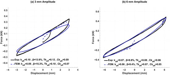
Figure 9.
FEM vs. experimental force–displacement loops for rotated Type 4 WRI at (tension, compression, and roll, 1 s period).
The assessment parameters for WRI Type 3 rotated by are summarized in Figure 8. At a 3 mm amplitude (Figure 8a), the FEM predicts an overall effective stiffness that is approximately 15% softer than the experimental value, and an effective damping that is 16% higher. The tensile stiffness is under-predicted by 26% and the compressive stiffness by 5%. Despite these offsets, the small-amplitude force–displacement curve closely matches the experimental shape and slope, with the largest deviation occurring in the peak tensile branch. At a 6 mm amplitude (Figure 8b), the overall hysteresis loop area from the FEM aligns well with the experiment. In this case, the FE stiffness is 12% softer in tension, while the predicted effective damping is 11% lower than measured. Similar results to the above were obtained for the WRI Type 2 rotated by ; therefore, those results are omitted here.
The assessment parameters for WRI Type 4 rotated by are summarized in Figure 9. At a 3 mm amplitude (Figure 9a), the FEM predicts an overall effective stiffness that is 13% softer and an effective damping that is 8% higher than the experimental values. Examining the branches separately, the model underestimates the tensile stiffness by 14% and the compressive stiffness by 29%, differences that manifest clearly in the force–displacement curve shapes. At a 6 mm amplitude (Figure 9b), the FEM stiffness remains 14% softer, while the predicted effective damping is 7% higher than measured. Despite these differences, the overall FEM loop closely follows the experimental curve, capturing both the global slope and loop area with relatively good fidelity.
The largest deviations occur under combined-mode deformation when the isolator is inclined and the response explores the extremes of the tensile/compressive branches. Quantitatively, for Type 3 at 30°, the model is 15% softer in overall stiffness at 3 mm and 12% softer in tensile stiffness at 6 mm; for Type 4 at 45°, the model is 13–14% softer in overall stiffness, while the compressive branch reaches 29% underprediction at 3 mm, reducing at 6 mm. At the system level (four WRIs at 45°, 3 Hz), force–displacement and moment–rotation metrics are generally within 10–17%, with the largest differences near peak moments/rotations. These trends show the error is configuration-dependent (angle, amplitude) and branch-specific, rather than systematic across all inclined dynamics. The observed bias is consistent with the model’s constant-section assumption and equivalent-viscous dissipation. Because the local interstrand stick-slip and amplitude-dependent hardening in the compressive branch are not explicitly modeled, the discrepancies grow when axial and bending effects couple most strongly (45°) and at branch extremes.
3.3. Results of Individual WRIs Under Sinusoidal Excitations Under Shear and Roll
Figure 10 presents the pure-roll hysteresis loops for the Type 1 isolator at 12 mm and 20 mm amplitudes. In both cases, the beam-based FEM closely reproduces the effective roll stiffness. The damping ratio, however, is overpredicted by 31% at 12 mm amplitude and by 25% at 20 mm amplitude. Despite this overestimation of damping, the shape and area of the hysteresis loops remain almost identical between FEM and experiment for the 20 mm amplitude, with some minor discrepancies on the peaks of the loops.
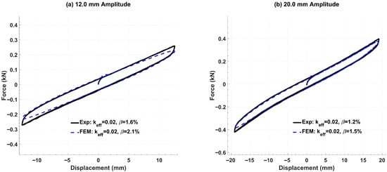
Figure 10.
Pure-roll hysteresis loops for the Type 1 isolator (10 s period).
Figure 11 presents the pure-shear force–displacement curve for the Type 1 isolator at a 6 mm amplitude. The FEM exactly reproduces the experimental effective stiffness. The effective damping is overpredicted by 52%. Nonetheless, the loop’s overall shape and slope align closely with the experiment, with minor differences in the tensile branch.
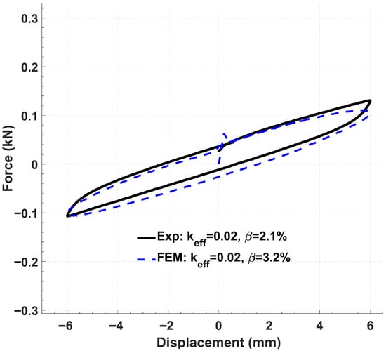
Figure 11.
Pure-shear hysteresis loop for the Type 1 isolator (6 mm amplitude, 100 s period).
4. FEM Response of a WRI-Based Isolation System Under Sinusoidal Excitations
The results of the FEM simulations of a WRI base platform subjected to sinusoidal accelerations are compared against the experimental results of Marin-Artieda and Han [15]. The isolation platform studied here employs four Type 5 WRIs inclined at 45°, forming a testbed to investigate how WRIs can be arranged to counteract seismic rocking of slender equipment. In the experiments, steel plates were sandwiched between wire-rope assemblies in multiple geometric arrangements to explore how the relative location of the platform’s center of mass (CM) and center of stiffness (CS) controls rocking behavior; these plates were modeled as rigid blocks in the FEM. By tilting the isolators “inward,” the platform’s CM is deliberately offset relative to its CS, producing a negative rotational stiffness that opposes overturning moments. Although the results presented in this section focus on the platform’s global force–displacement and moment–rotation loops rather than direct rocking measurements, they nonetheless support the evaluation of the FEM’s ability to capture complex, non-standard configurations where combined tension–compression–roll responses govern the system’s behavior. Figure 12 shows one of the experimental prototype platforms fitted with four Type 5 inclined WRIs at and its corresponding FE model in front and plan views.
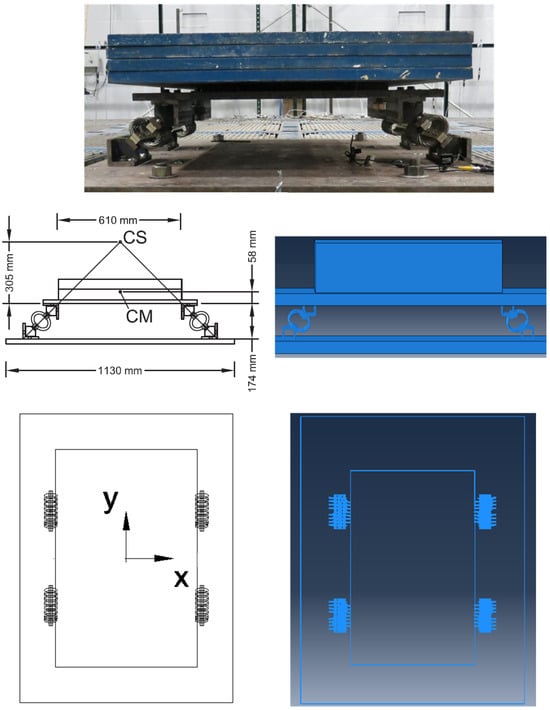
Figure 12.
WRI-based isolation system with inclined isolators.
Figure 13 presents the average horizontal (x-direction) force-displacement response of the WRI platform under two unidirectional x-direction, 3 Hz sinusoidal excitations. At the lower amplitude (0.55 g; Figure 13a), the FEM reproduces the experimental slope and curve shape with good fidelity: effective stiffness is within 5%, and hysteresis area differs by 10%. The FEM loop appears slightly smoother with reduced “pinching” at reversals. Under the higher excitation (1.25 g; Figure 13b), discrepancies grow at the negative-load branch. The FEM underestimates peak forces and loop area by approximately 15%, reflecting diminished accuracy in stiffness hardening and energy dissipation at large deformations.
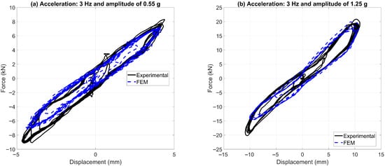
Figure 13.
Platform force–displacement loops.
Figure 14 compares the FEM and experimental moment–rotation responses of the 45° tension-compression-roll platform (CM–CS offset = −247 mm, counter-rocking configuration) under 3 Hz sinusoidal excitation at amplitudes of 0.55 g (Figure 14a) and 1.25 g (Figure 14b).
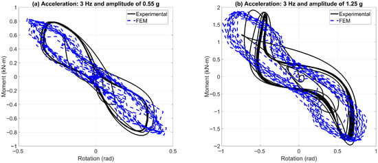
Figure 14.
Moment-rotation loops with negative CM–CS offset.
At the lower amplitude (Figure 14a), the FEM predicts the negative rotational stiffness to within 10% of the experimental value. Although the model reproduces the overall hysteretic envelope, it does not capture the distinctive “waist” of the experimental loops where the branches are widest at the peak loads, but pinch sharply near zero rotation. Its largest discrepancy appears at the peak moments and rotations, which are slightly overestimated. The total hysteresis area differs by 15%, indicating that proportional damping provides a reasonable estimate of energy dissipation for small-to-moderate rotations but fails to reproduce the waisted loop shape. Moreover, the experimental loops transition smoothly at load reversals, whereas the FEM loops exhibit pronounced pinching at those points. Under the higher amplitude excitation (Figure 14b), the differences become more pronounced near the loop extremities. The model overestimates peak moments by 14% and peak rotations by approximately 18%, and the enclosed hysteresis area is approximately 17% larger. This discrepancy reflects reduced accuracy in both stiffness hardening and damping at large rotations. Additionally, the experimental loops exhibit stiffening in the positive-moment branch, a behavior that is not captured by the FEM.
5. Vertical Travel Distance of WRIs
One critical design parameter for WRI-based platforms is the vertical travel distance d, defined as the peak vertical deformation of the WRIs under the platform load (see Figure 15). This travel becomes especially important when WRIs are inclined, since excessive deformation can lead to contact between WRIs and attachments, potentially causing mechanical interference and impact.
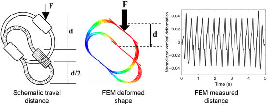
Figure 15.
Vertical travel distance of WRIs.
By quantifying the travel distance in the FEM during design and prior to fabrication, designers can ensure adequate clearance between attachment bars and avoid collisions. FEM can facilitate the monitoring of the travel distances across different loading amplitudes and inclinations, enabling rapid evaluation of safety margins and serviceability limits without resorting to costly prototype testing.
6. Discussion
Building upon foundational validation efforts, this study demonstrates that a constant-property Timoshenko beam FEM, with tuned Rayleigh damping, offers a computationally efficient yet sufficiently accurate framework for simulating wire-rope isolator behavior under diverse loading conditions. Initial benchmarking against the work of Breslavsky et al. [18], using the Abaqus B31 beam element with nonlinear geometry (NLGEOM) and a linear-elastic material, confirmed the model’s ability to capture asymmetric ring nonlinearities. The FEM results remain close to the analytical curve, and the observed 12% deviation at the maximum normalized deflection is largely due to the steepness of the curve in that region. Although this underestimation maintained acceptable accuracy across the large-deformation regime, it validates the model’s suitability for further application.
Leveraging the calibrated framework, the modeling approach was extended to full helical WRI geometries encompassing five distinct types. A single set of effective cross-sectional properties, including area and moments of inertia, was calibrated against vendor-provided quasi-static force–displacement curves in standard working modes. This representative set was then applied uniformly across all beam elements. The simplified beam representation reproduced the nonlinear stiffness characteristics of the three principal deformation modes with good fidelity, requiring only minor tuning of the section properties. In the more complex inclined configuration, which couples shear/roll with tension–compression, discrepancies emerged at larger displacements. Here, the FEM stiffness predictions deviated from the experimental curves by approximately 15–20%. These offsets reflect the difficulty of capturing combined geometric nonlinearity and interstrand friction with a single, constant-property cross-section. It is important to acknowledge that no single set of constant section properties can reproduce all loading configurations with equal accuracy; however, the model remains a practical and accessible tool for global stiffness estimation. Overall, the constant-property beam approximation proved to be a reliable and computationally efficient surrogate for representing WRI behavior, particularly in the standard working modes.
Dynamic analyses under sinusoidal excitation further underscored the FE model’s balance between predictive fidelity and computational tractability. In pure deformation modes, the FEM force–displacement responses closely matched experimental data in both stiffness and hysteretic loop morphology. In inclined configurations, however, the model underestimated stiffness and did not capture well loop shapes at peak locations under low-amplitude (3 mm) excitation. At moderate amplitudes (6 mm), the predicted loops aligned more closely with experimental observations. It should be noted that dynamic validation in this study was restricted to sinusoidal excitation tests performed within the limits of the available equipment. To strengthen the generalization of the framework, future work may incorporate independent experimental datasets and publicly available dynamic test results for cross-validation. Such efforts will broaden the evaluation of the model’s predictive capability across a wider range of loading rates, amplitudes, and orientations.
To evaluate the model’s performance in a system-level context, a platform testbed supported by four -inclined Type 5 WRIs was analyzed under a non-standard “rocking-control” configuration. When subjected to acceleration excitations of 0.55 g and 1.25 g, the model reproduced the global platform stiffness and energy dissipation within 10–20% of experimental measurements. Although it did not capture the detailed hysteretic loop shapes governed by interstrand friction, the model demonstrated robustness and predictive adequacy for global response metrics.
The results obtained with the platform testbed are particularly valuable for designing WRI isolation systems that include inclined configurations. Experimental evidence indicates that localized deformations and force–displacement relationships in inclined WRIs are complex and not fully captured by conventional WRI modeling approaches. Compounding this challenge, experimental data for inclined configurations are often unavailable, making it difficult to establish the parameters required for conventional WRI models. In such cases, the ability of the present framework to provide reliable global performance predictions becomes especially useful.
The proposed approach delivers robust estimates of system-level stiffness and energy dissipation, while also offering estimates of local deformation demands that are difficult to capture with traditional WRI modeling strategies. Although the simplified beam formulation does not reproduce detailed hysteretic morphology, it achieves a practical balance between computational efficiency and predictive fidelity. This makes the framework well-suited for engineering design applications when overall platform performance is the primary concern and detailed loop shapes are of secondary importance.
The inability of the FEM to replicate pinched hysteretic loops observed experimentally is primarily due to unmodeled physical mechanisms such as interstrand stick–slip, contact reconfiguration, geometric uncoiling, and axial realignment. These nonlinear effects intensify with increasing amplitude and contribute to hardening behavior not captured by the constant-parameter Rayleigh damping formulation. As a result, the FEM produces smoother hysteresis loops and underestimates stiffness at higher deformation levels.
The constant-property Timoshenko beam model with tuned damping offers a pragmatic compromise between modeling simplicity and predictive capability. While it does not capture all local nonlinearities, it effectively simulates global stiffness and energy dissipation across a range of configurations and loading regimes. Defining upper and lower performance bounds and validating them against experimental data can further enhance the model’s robustness, ensuring its continued utility as a cost-effective tool for engineering analysis and design.
Overall, the present FEM framework, based on constant-property Timoshenko beam elements with tuned Rayleigh damping, provides a practical compromise between simplicity and predictive capability. It reliably captures global stiffness and energy dissipation across modes, with deviations from experiments typically within 10–20%. However, the model cannot reproduce pinched hysteresis loops or branch-specific hardening effects observed experimentally, particularly in inclined configurations. These discrepancies stem from unmodeled physical mechanisms such as interstrand stick–slip, contact reconfiguration, geometric uncoiling, and axial realignment, which intensify with amplitude and generate rate-independent hysteresis features not captured by viscous damping. As a result, the FEM produces smoother loops and underestimates stiffness at large deformations. Future improvements could incorporate variable section properties that evolve with geometry and embedded frictional/contact laws (wire–wire and rope–seat interfaces, preload-dependent hysteresis) to better capture local morphology. Mechanical formulations that resolve the rope’s hierarchical structure [9] or hybrid strategies using piecewise-linearized beam models [10] offer promising directions. In addition, to support long-term prediction, we outline a bounded damage index driven by cumulative dissipated energy and cycle count that scales the effective section properties and damping surrogate. Future possible work may calibrate these coefficients using repeated-cycle tests at representative amplitudes and frequencies, enabling the model to simulate progressive stiffness degradation and dissipation loss.
7. Conclusions
This study introduced and validated a simplified finite-element modeling framework for wire-rope isolators, employing constant-property Timoshenko beam elements with Rayleigh-type damping to capture the essential nonlinear stiffness and hysteretic behavior of WRIs under diverse loading conditions. The model was benchmarked against analytical solutions for ring-type geometries and demonstrated strong agreement, with less than 12% deviation in normalized deflection, thereby confirming its ability to capture large-strain geometric nonlinearities.
The model was extended to five full-scale helical WRI types, using a single set of effective cross-sectional properties calibrated against vendor-supplied quasi-static data. In conventional working modes, pure tension-compression, shear, and roll, the model reproduced experimental stiffness within 5%, and in inclined configurations, it maintained accuracy within 15–20% at moderate displacements. However, deviations increased at larger displacements, particularly under combined-mode loading, reflecting the limitations of the constant-property approximation in capturing coupled geometric and frictional nonlinearities.
Dynamic simulations under sinusoidal excitation further validated the model’s predictive capability. In pure modes, the FEM closely matched experimental force–displacement loops in both shape and energy dissipation. In inclined configurations, the model underestimated stiffness and failed to capture loop pinching at low amplitudes (3 mm), though agreement improved at moderate amplitudes (6 mm). These results confirm the model’s reliability for service-level deformations while highlighting its limitations in representing nonlinear hardening and asymmetric hysteresis at extreme or multimode deformation.
At the system level, the model was applied to a WRI-based isolation platform with four 45°-inclined WRIs subjected to base accelerations. The FEM reproduced platform stiffness and energy dissipation within 10–20% of experimental values across both 0.55 g and 1.25 g excitations. While the model did not capture detailed loop morphologies such as pinching and asymmetric branch stiffness, it successfully predicted global response trends, including negative rotational stiffness in counter-rocking configurations.
This study also demonstrated the model’s utility in estimating vertical travel distances of inclined WRIs, a critical design parameter for avoiding mechanical interference. By enabling rapid evaluation of deformation limits across loading amplitudes and orientations, the model supports practical design workflows without the need for exhaustive physical testing.
The constant-property Timoshenko beam model with tuned damping offers a computationally efficient and sufficiently accurate tool for simulating WRI behavior in both component-level and system-level applications. While it does not resolve all local nonlinearities, particularly those arising from interstrand friction and contact reconfiguration, it provides a robust foundation for performance-based design.
Compared with phenomenological approaches such as Bouc-Wen and generalized hysteresis models, the present beam-based framework offers a computationally efficient and physically interpretable alternative that captures multimode global stiffness with minimal calibration effort. At the same time, the constant-property assumption limits its ability to reproduce local phenomena such as pinched loops, asymmetric branch stiffness, and nonlinear hardening in inclined configurations. These discrepancies are linked to unmodeled interstrand stick–slip, contact reconfiguration, and coupled axial–rotational effects.
It is worth noting that the accuracy of the framework can be further improved by incorporating direction-dependent stiffness corrections, rate-independent hysteresis laws, and geometric nonlinear strengthening rules to broaden validation. Additional refinements, such as degradation indices for long-term cyclic behavior, sensitivity and uncertainty analyses, and the inclusion of environmental effects such as temperature and corrosion, would also enhance the robustness and generalization of the model. While these refinements can increase accuracy, they also introduce modeling and computational effort. In engineering practice, the essential requirement is to balance accuracy with efficiency, depending on the application and design needs. For this reason, the design practice framework should be maintained as a simple and cost-effective tool that is straightforward to implement, ensuring accessibility for practical design use. In summary, this study establishes a simplified beam-based framework that balances accuracy with computational efficiency, providing a reliable baseline for performance-based design. At the same time, it offers the flexibility to incorporate higher-fidelity extensions when practitioners determine that additional accuracy, such as detailed hysteretic morphology or long-term degradation effects, is justified.
Funding
This material is based on work supported by the National Science Foundation (NSF) under Grant No. CMMI 1150462.
Data Availability Statement
FE models are available on GitHub: https://github.com/cmarin1/FEM_WRIs. accessed on 1 July 2025.
Acknowledgments
The author gratefully acknowledges Hamid Ghasemi, a former student, for his contributions to finite-element modeling during his academic training. His engagement with the modeling concepts presented in this work was instrumental in shaping the early stages of the research. Although Ghasemi initially expressed interest in co-authorship, the corresponding author was unable to locate or contact him during the manuscript preparation and revision process. In accordance with authorship guidelines and due to the absence of his review and approval of the final manuscript, he is recognized here with appreciation and respect for his contributions. The author also acknowledges the VMC Group for generously donating the wire-rope isolators used in this study. Any opinions, findings, and conclusions or recommendations expressed in this paper are those of the author and do not necessarily reflect the views of the supporting organizations.
Conflicts of Interest
The author declares no conflicts of interest. The sponsors had no role in the design of the study; in the collection, analysis, or interpretation of the data; in the writing of the manuscript; or in the decision to publish the results.
Abbreviations
The following abbreviations are used in this manuscript:
| WRI | Wire-Rope Isolator |
| FE | finite-element |
| FEM | Finite-Element Model |
| Normalized deformation | |
| P | Pressure |
| Strand area | |
| Area moment of inertia | |
| principal moments of inertia | |
| principal moments of inertia | |
| Overall effective stiffness | |
| Tensile effective stiffness | |
| Compressive effective stiffness | |
| Effective damping | |
| Maximum tensile force | |
| Maximum compressive force | |
| Maximum tensile displacement | |
| Maximum compressive displacement | |
| stiffness-proportional damping coefficient | |
| CM | Center of Mass |
| CS | Center of Stiffness |
| Hz | Hertz (unit of frequency) |
| g | Acceleration due to gravity (9.81 m/s2) |
| F | Force |
| mm | Millimeter |
| kN | Kilonewton |
| s | Second |
| d | Vertical travel distance of WRI |
| H | Isolator Height |
| W | Isolator Width |
| L | Isolator Length |
| S | Spacing, center-to-center distance between ropes |
References
- Tinker, M.L.; Cutchins, M.A. Damping phenomena in a wire rope vibration isolation system. J. Sound Vib. 1992, 157, 7–18. [Google Scholar] [CrossRef]
- Salvatore, A.; Carboni, B.; Chen, L.Q.; Lacarbonara, W. Nonlinear dynamic response of a wire rope isolator: Experiment, identification and validation. Eng. Struct. 2021, 238. [Google Scholar] [CrossRef]
- Leblouba, M.; Balaji, P.S.; Rahman, M.E. Quasi-static cyclic behavior of wire rope isolators: Comprehensive experimental study and improved mathematical modeling. Heliyon 2022, 8, e10944. [Google Scholar] [CrossRef] [PubMed]
- Wen, Y.K. Method for random vibration of hysteretic systems. J. Eng. Mech. Div. 1976, 102, 249–263. [Google Scholar] [CrossRef]
- Demetriades, G.F.; Constantinou, M.C.; Reinhorn, A.M. Study of wire rope systems for seismic protection of equipment in buildings. Eng. Struct. 1993, 15, 321–334. [Google Scholar] [CrossRef]
- Ni, Y.; Ko, J.M.; Wong, C.W.; Zhan, S. Modelling and identification of a wire-cable vibration isolator via a cyclic loading test Part 2: Identification and response prediction. Proc. Inst. Mech. Eng. Part I J. Syst. Control Eng. 1999, 213, 173–182. [Google Scholar] [CrossRef]
- Maleki, M.; Ahmadian, H.; Rajabi, M. A modified Bouc–Wen model to simulate asymmetric hysteresis loop and stochastic model updating in frictional contacts. Int. J. Solids Struct. 2023, 269, 112212. [Google Scholar] [CrossRef]
- Vaiana, N.; Marmo, F.; Sessa, S.; Rosati, L. Modeling of the Hysteretic Behavior of Wire Rope Isolators Using a Novel Rate-Independent Model. In Nonlinear Dynamics of Structures, Systems and Devices; Lacarbonara, W., Balachandran, B., Ma, J., Machado, J.A.T., Stepan, G., Eds.; Springer Nature: Cham, Switzerland, 2020; pp. 309–317. [Google Scholar] [CrossRef]
- Foti, F.; Galeazzi, J.; Martinelli, L. On the modelling of the hysteretic behaviour of wire rope isolators. In Proceedings of the AIMETA 2019—XXIV Conference of the Italian Association of Theoretical and Applied Mechanics, Rome, Italy, 15–19 September 2019. [Google Scholar]
- Bonisoli, E.; Dimauro, L.; Venturini, S.; Cavallaro, S.P. Experimental Detection of Nonlinear Dynamics Using a Laser Profilometer. Appl. Sci. 2023, 13, 3295. [Google Scholar] [CrossRef]
- WJiang, G.; Yao, M.S.; Walton, J.M. A concise finite-element model for simple straight wire rope strand. Int. J. Mech. Sci. 1999, 41, 143–161. [Google Scholar] [CrossRef]
- Nawrocki, A.; Labrosse, M. A finite-element model for simple straight wire rope strands. Comput. Struct. 2000, 77, 345–359. [Google Scholar] [CrossRef]
- Elata, D.; Eshkenazy, R.; Weiss, M.P. The mechanical behavior of a wire rope with an independent wire rope core. Int. J. Solids Struct. 2004, 41, 1157–1172. [Google Scholar] [CrossRef]
- Gai, J.; Yan, K.; Deng, Q.; Sun, M.; Ye, F. A finite-element model for a 6 × K31WS + FC wire rope and a study on its mechanical responses with or without wire breakage. Appl. Sci. 2023, 13, 8407. [Google Scholar] [CrossRef]
- Marin-Artieda, C.; Han, X. Energy dissipation platforms based on wire rope isolators for the seismic protection of equipment. In Proceedings of the 16th World Conference on Earthquake, 16WCEE 2017, Santiago, Chile, 9–13 January 2017; pp. 1–12. [Google Scholar]
- Sapountzakis, E.J.; Dourakopoulos, J.A. Nonlinear dynamic analysis of Timoshenko beams by BEM. Part I: Theory and numerical implementation. Nonlinear Dyn. 2009, 58, 295–306. [Google Scholar] [CrossRef]
- Dassault Systèmes. Abaqus 6.14 Documentation; Dassault Systèmes Simulia Corp.: Providence, RI, USA, 2016. [Google Scholar]
- Breslavsky, I.D.; Amabili, M.; Legrand, M.; Alijani, F. Axisymmetric deformations of circular rings made of linear and Neo-Hookean materials under internal and external pressure: A benchmark for finite-element codes. Int. J. Nonlinear Mech. 2016, 84, 39–45. [Google Scholar] [CrossRef]
- Foss, G.C. Modal damping estimates from static load-deflection curves. Shock Vib. Dig. 2006, 38, 535–536. [Google Scholar]
- Hall, J.F. Problems encountered from the use (or misuse) of Rayleigh damping in nonlinear analysis. Earthq. Eng. Struct. Dyn. 2006, 35, 525–545. [Google Scholar] [CrossRef]
- Alipour, A.; Zareian, F. Study Rayleigh damping in structures: Uncertainties and treatments. In Proceedings of the 14th World Conference on Earthquake Engineering, Beijing, China, 12–17 October 2008. Paper No. 14-0243. [Google Scholar]
- Jehel, P.; Léger, P.; Ibrahimbegovic, A. Initial versus tangent stiffness-based Rayleigh damping in inelastic time history seismic analyses. Earthq. Eng. Struct. Dyn. 2014, 43, 467–484. [Google Scholar] [CrossRef]
Disclaimer/Publisher’s Note: The statements, opinions and data contained in all publications are solely those of the individual author(s) and contributor(s) and not of MDPI and/or the editor(s). MDPI and/or the editor(s) disclaim responsibility for any injury to people or property resulting from any ideas, methods, instructions or products referred to in the content. |
© 2025 by the author. Licensee MDPI, Basel, Switzerland. This article is an open access article distributed under the terms and conditions of the Creative Commons Attribution (CC BY) license (https://creativecommons.org/licenses/by/4.0/).